EP0796798A2 - Cale d'emballage - Google Patents
Cale d'emballage Download PDFInfo
- Publication number
- EP0796798A2 EP0796798A2 EP97250066A EP97250066A EP0796798A2 EP 0796798 A2 EP0796798 A2 EP 0796798A2 EP 97250066 A EP97250066 A EP 97250066A EP 97250066 A EP97250066 A EP 97250066A EP 0796798 A2 EP0796798 A2 EP 0796798A2
- Authority
- EP
- European Patent Office
- Prior art keywords
- cushion
- corner
- wall
- section
- packaging
- Prior art date
- Legal status (The legal status is an assumption and is not a legal conclusion. Google has not performed a legal analysis and makes no representation as to the accuracy of the status listed.)
- Withdrawn
Links
- 238000004806 packaging method and process Methods 0.000 title claims abstract description 31
- 239000000463 material Substances 0.000 claims description 11
- 238000009960 carding Methods 0.000 claims description 6
- 239000000853 adhesive Substances 0.000 claims description 5
- 230000001070 adhesive effect Effects 0.000 claims description 4
- 238000004804 winding Methods 0.000 claims description 3
- 238000012856 packing Methods 0.000 claims description 2
- 238000004519 manufacturing process Methods 0.000 description 3
- 210000001061 forehead Anatomy 0.000 description 2
- 238000003780 insertion Methods 0.000 description 2
- 230000037431 insertion Effects 0.000 description 2
- 239000005022 packaging material Substances 0.000 description 2
- 210000002105 tongue Anatomy 0.000 description 2
- 230000006978 adaptation Effects 0.000 description 1
- 238000006073 displacement reaction Methods 0.000 description 1
- 230000000694 effects Effects 0.000 description 1
- 238000005192 partition Methods 0.000 description 1
- 239000002356 single layer Substances 0.000 description 1
Images


Classifications
-
- B—PERFORMING OPERATIONS; TRANSPORTING
- B65—CONVEYING; PACKING; STORING; HANDLING THIN OR FILAMENTARY MATERIAL
- B65D—CONTAINERS FOR STORAGE OR TRANSPORT OF ARTICLES OR MATERIALS, e.g. BAGS, BARRELS, BOTTLES, BOXES, CANS, CARTONS, CRATES, DRUMS, JARS, TANKS, HOPPERS, FORWARDING CONTAINERS; ACCESSORIES, CLOSURES, OR FITTINGS THEREFOR; PACKAGING ELEMENTS; PACKAGES
- B65D81/00—Containers, packaging elements, or packages, for contents presenting particular transport or storage problems, or adapted to be used for non-packaging purposes after removal of contents
- B65D81/02—Containers, packaging elements, or packages, for contents presenting particular transport or storage problems, or adapted to be used for non-packaging purposes after removal of contents specially adapted to protect contents from mechanical damage
- B65D81/05—Containers, packaging elements, or packages, for contents presenting particular transport or storage problems, or adapted to be used for non-packaging purposes after removal of contents specially adapted to protect contents from mechanical damage maintaining contents at spaced relation from package walls, or from other contents
- B65D81/053—Corner, edge or end protectors
- B65D81/055—Protectors contacting three surfaces of the packaged article, e.g. three-sided edge protectors
- B65D81/056—Protectors contacting three surfaces of the packaged article, e.g. three-sided edge protectors the surfaces being generally perpendicular to each other, e.g. three-sided corner protectors
-
- B—PERFORMING OPERATIONS; TRANSPORTING
- B65—CONVEYING; PACKING; STORING; HANDLING THIN OR FILAMENTARY MATERIAL
- B65D—CONTAINERS FOR STORAGE OR TRANSPORT OF ARTICLES OR MATERIALS, e.g. BAGS, BARRELS, BOTTLES, BOXES, CANS, CARTONS, CRATES, DRUMS, JARS, TANKS, HOPPERS, FORWARDING CONTAINERS; ACCESSORIES, CLOSURES, OR FITTINGS THEREFOR; PACKAGING ELEMENTS; PACKAGES
- B65D81/00—Containers, packaging elements, or packages, for contents presenting particular transport or storage problems, or adapted to be used for non-packaging purposes after removal of contents
- B65D81/02—Containers, packaging elements, or packages, for contents presenting particular transport or storage problems, or adapted to be used for non-packaging purposes after removal of contents specially adapted to protect contents from mechanical damage
- B65D81/05—Containers, packaging elements, or packages, for contents presenting particular transport or storage problems, or adapted to be used for non-packaging purposes after removal of contents specially adapted to protect contents from mechanical damage maintaining contents at spaced relation from package walls, or from other contents
- B65D81/053—Corner, edge or end protectors
- B65D81/057—Protectors contacting four surfaces of the packaged article, e.g. four-sided corner protectors
-
- B—PERFORMING OPERATIONS; TRANSPORTING
- B65—CONVEYING; PACKING; STORING; HANDLING THIN OR FILAMENTARY MATERIAL
- B65D—CONTAINERS FOR STORAGE OR TRANSPORT OF ARTICLES OR MATERIALS, e.g. BAGS, BARRELS, BOTTLES, BOXES, CANS, CARTONS, CRATES, DRUMS, JARS, TANKS, HOPPERS, FORWARDING CONTAINERS; ACCESSORIES, CLOSURES, OR FITTINGS THEREFOR; PACKAGING ELEMENTS; PACKAGES
- B65D2581/00—Containers, packaging elements, or packages, for contents presenting particular transport or storage problems, or adapted to be used for non-packaging purposes after removal of contents
- B65D2581/02—Containers, packaging elements, or packages, for contents presenting particular transport or storage problems, or adapted to be used for non-packaging purposes after removal of contents specially adapted to protect contents from mechanical damage
- B65D2581/05—Containers, packaging elements, or packages, for contents presenting particular transport or storage problems, or adapted to be used for non-packaging purposes after removal of contents specially adapted to protect contents from mechanical damage maintaining contents at spaced relation from package walls, or from other contents
- B65D2581/051—Details of packaging elements for maintaining contents at spaced relation from package walls, or from other contents
- B65D2581/052—Materials
- B65D2581/053—Paper in general, e.g. paperboard, carton, molded paper
-
- B—PERFORMING OPERATIONS; TRANSPORTING
- B65—CONVEYING; PACKING; STORING; HANDLING THIN OR FILAMENTARY MATERIAL
- B65D—CONTAINERS FOR STORAGE OR TRANSPORT OF ARTICLES OR MATERIALS, e.g. BAGS, BARRELS, BOTTLES, BOXES, CANS, CARTONS, CRATES, DRUMS, JARS, TANKS, HOPPERS, FORWARDING CONTAINERS; ACCESSORIES, CLOSURES, OR FITTINGS THEREFOR; PACKAGING ELEMENTS; PACKAGES
- B65D2581/00—Containers, packaging elements, or packages, for contents presenting particular transport or storage problems, or adapted to be used for non-packaging purposes after removal of contents
- B65D2581/02—Containers, packaging elements, or packages, for contents presenting particular transport or storage problems, or adapted to be used for non-packaging purposes after removal of contents specially adapted to protect contents from mechanical damage
- B65D2581/05—Containers, packaging elements, or packages, for contents presenting particular transport or storage problems, or adapted to be used for non-packaging purposes after removal of contents specially adapted to protect contents from mechanical damage maintaining contents at spaced relation from package walls, or from other contents
- B65D2581/051—Details of packaging elements for maintaining contents at spaced relation from package walls, or from other contents
- B65D2581/058—Edge or corner protectors connected to each other by separate elements
Definitions
- the invention relates to a packaging cushion, comprising facing, interconnected and variably spacable cushion elements. Parts with different edge lengths can be packed with the same packaging pad.
- the cushion can have two corners of small housings with edge lengths of e.g. Border 100 mm to 200 mm. Using four of the upholstered double corners, all-round protection for sensitive cuboid parts, e.g. manufacture electronic devices.
- the invention also relates to a blank for forming the cushion corner of the packaging cushion.
- a known cushion of the generic type consists of soft rubber-like plastic material which can only be stretched with considerable force for longer edge lengths due to the relatively high material restoring force. Apart from the fact that such upholstery also tends to have undesirable curvatures along the edge length, these are products which have a significant impact on the environment, both in terms of manufacture and disposal, whereby it must be taken into account that the upholstery is used in very large numbers and mostly after single use.
- the invention has for its object to provide a packaging cushion with removable cushion corners, which is equally dimensionally stable for different edge lengths, to a relatively large extent and in convenient handling to the desired Edge length is adjustable and can be made from environmentally friendly material.
- the packaging cushion has at least two upholstery corners which are each made up of at least one cardboard, corrugated cardboard or similar material and are each provided with at least one of the cushion elements which can be distanced from one another , wherein the upholstery corners are connected to one another by means of a push-slide connection so as to be movable relative to one another.
- the packaging cushion according to the invention which can be produced from environmentally compatible material such as corrugated cardboard, can be brought to the desired distance between facing end-facing corner cushion elements simply by translatory displacement of two cushion corners. These can be relatively far apart in precise alignment, e.g. by 30 to 50% of the smallest distance between the cushion elements.
- the desired distance between the forehead upholstery elements is set very conveniently, since due to the plug-and-slide connection there are no restoring forces which increase significantly with increasing spreading in the known plastic double corner and thus hinder handling there. It is particularly advantageous that the upholstery double corner according to the invention is in the maximally pulled apart state, i.e. can be delivered with the greatest spacing of the forehead upholstery elements and can then be pushed together on the goods to be packaged to the desired corner spacing by simple sliding movement.
- a wall having a flat gap is formed on at least one cushion corner, the flat gap interacting with a tongue-like, correspondingly flat plug-in element.
- the flat gap forms a pocket-like flat receptacle and guide, into which the plug-in element is a sliding part with friction resistance due to the cutting material.
- the smoothness of the push-slide connection can advantageously be increased, for example, in that the corrugations of the plug-in element and the receiving element extend parallel in the case of upholstered corners made of corrugated cardboard.
- each upholstered corner has an inner corner closed with walls at right angles to one another.
- each upholstered corner forms a three-sided upholstery in the inner corner at every sliding position, and thus, on the whole, very stable upholstery. This can be used particularly advantageously in outer cartons whose carton stability as such is relatively low.
- the plug element of the upholstery corner connection can be provided as a separate element with tongues on opposite sides, an associated plug receptacle then being assigned to each upholstery corner.
- the plug-in element can advantageously be designed with a single-layer shaft position covered on both sides, wherein it is expediently provided with a height corresponding to the rear wall height or the floor depth of the double upholstery corner to form a closed wall extending to the inner longitudinal corner of the upholstery.
- a particularly simple and functional design consists in that a flat gap forming the sliding guide receptacle is formed by the space between a wall turned inside out.
- a particularly advantageous embodiment of the plug element formed by a flat section is that it is part of a connection card wall, which is particularly advantageous as is provided between an outer and an inner wall firmly enclosed wall.
- Such a three-walled carding / winding wall can advantageously also be provided as a cushion element on the rear or bottom side in the double cushion corner.
- a particularly simple and expedient cut for the cushion corner of the packaging cushion has at least one section forming a corner wall of the erected cushion corner, which is connected to a cut element forming a plug-in receptacle of the sliding connection.
- at least three sections lying flat in the blank and hinged to one another by means of folding lines are provided, two sections being articulated on a corner section in the blank and at least one of the corner wall sections being connected to a section forming a plug-in receptacle.
- a blank according to the invention can also expediently have a surface section forming a plug element, which is further advantageously provided as a component of a cardboard wall.
- the cut can be made very simple in that advantageously a sequence of at least four almost identical rectangular surface sections with parallel fold lines are articulated to one another on the narrow side.
- a double section intended for forming the cardboard wall is articulated on at least one central section of the sequence of sections by means of fold lines which are directed perpendicular to the fold lines articulating the successive sections.
- a particular advantage with regard to cost-effective production is that the blanks are made the same for both cushion corners of the packaging cushion can, the blanks advantageously also having two identically identical plug-in surface sections.
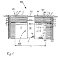
- the packaging cushion according to FIG. 1 comprises two cushion corners 101 and 102, which have identical walls 1 to 9 and cushions 901, 902 which are identical. Overall, a double corner cushion is formed which, with its space 105 which is open on two sides at a corner, accommodates the part of the packaging material (not shown) to be cushioned, the packaging material at the distance of its edge length L on the long side and on the end face at two corners.
- the description is based on the upholstery corner 101 on the right in FIG. 1.
- This comprises a connecting wall 300, which consists of three parallel walls, as shown on the rear, namely the outer rear wall 3, the inner rear wall 2 and the intermediate connecting wall 1.
- the end wall 700 comprises four parallel walls, namely the end outer wall 7, the end partitions 6 and 8 and the end inner wall 9.
- the bottom wall 400 comprises two parallel walls spaced apart by a space 51, namely a gap outer wall 4 and a gap inner wall 5.
- a cushion element 901 forming a cuboid-shaped cushion block is attached by means of adhesive, while on the rear inner wall 2 a cuboid-shaped cushion element 902 forming a cushion block is attached by adhesive.
- cuboidal cushion elements 902 (not shown) can be arranged on the inner wall 5 of the cushion corner 101 and on the inner wall 2 of the cushion corner 102.
- a one-piece cushion element with an L-shaped profile cross section can also be expediently provided as a back and floor cushion.
- the front cushion 901 then advantageously engages in the L-profile.
- the cuboid cushion elements 901 and 902 are not shown in the views of FIGS. 2A to C.
- the connecting wall 1 has an intermediate section 11, which is fixed between the walls 2 and 3 with the same area.
- the intermediate section 11 merges into a plug-in section 10, which forms a flat tongue-shaped plug-in element and extends outside the two walls 2 and 3 in a straight line.
- the surface gap 51 between the walls 4 and 5 form a plug-in receptacle for the corresponding plug-in section 10 of the other cushion corner 102.
- the plug-in section 10 of the connecting wall 1 is so long that it comes fully or partially into engagement with the wall gap 51 of the cushion corner 102, which is completely identical to the cushion corner 101, in a flat plug-slide connection.
- the spatial position of the cushion corner 102 in relation to the cushion corner 101 can be seen e.g. Imagine that a cushion corner 102 in the position shown for the cushion corner 101 is first rotated by 180 ° about the axis A1 between the walls 2 and 9 (see FIG. 2A) and then a rotation of 90 ° from this position the wall axis A2 takes place between the walls 2 and 5 (see FIG. 2C).
- the two cushion corners 101 and 102 are connected to one another over the entire surface on the rear wall and on the bottom wall of the packaging cushion 100 by means of the plug-in sections 10 forming the web walls.
- 1 shows a position in which the mutually perpendicular and oppositely directed plug-in surface sections 10 of the two upholstery corners 101, 102 engage approximately half in the respectively associated wall surface gap 51. This means that, based on the maximum distance in the fully extended sliding position of the two cushion corners 101, 102, the sliding distance is reduced by approximately 50%. The sliding adjustment to the desired edge length L between the corners of a product to be packaged can thus be conveniently set.
- the end walls 700 additionally form end cushion elements. Possibly. the glued-in block pad elements 901 can also be omitted.
- the cushioning effects of the connecting wall 300 and the intermediate wall 400 may also be sufficient, so that the block cushioning elements 902 can then expediently be omitted.
- Fig. 3 shows in the embodiment a flat lying blank according to the invention, which is particularly suitable and adapted to form the cushion corner of a packaging cushion according to the invention.
- the cushion corner 101 or 102 according to FIGS. 1, 2A to 2C can be formed in a simple manner.
- the sections forming the walls 1 to 9 are provided with the same reference numerals but with a prime.
- the plug-in section 10 of the cushion corners 101, 102 according to FIGS. 1 to 2C is provided with a curve for easier insertion into the wall gap 51, an edge beveling of the plug-in section 10 is provided for this purpose in the blank according to FIG. 3.
- the blank has a row arrangement of sections 1 'to 5' which are rectangular and essentially the same, the articulation on the narrow sides taking place successively by means of parallel fold lines 30, 40 and 50.
- the outer section 5 ' is articulated to the section 4' by means of the double fold line 50, and the other outer section 2 'is articulated to the section 3' via the double fold line 30.
- sections 3 'and 4' each have two sections 7 ', 8' and 6 ', 9' connected by double folding lines.
- Sections 6 'to 9' have essentially the same square base area, which is determined by the long side length of the rectangular sections.
- the section 4 ' forms a corner section in the blank, to which the sections 3', 6 'are articulated by means of fold lines 40.
- a section 1 ' is articulated to the outer narrow side of section 2' in the blank by means of a double folding line 20.
- This section 1 ' is divided into sections 10 and 11 which are identical to the rectangular section 2'.
- the plug section 10 thus formed is at right angles from the long side of the cutting sequence 2 'to 5' and on that of the double sections 6 ', 9'; 7 ', 8' opposite side.
- the section 1 ' is first folded up and folded over the double fold line 20, the width of which corresponds approximately to the material thickness, for the 180 ° folding.
- Section 11 has the same area as section 2 '.
- the two sections 1 ', 2' are folded together by 180 ° around the double folding line 30 onto the section 3 'by folding up.
- Sections 4 ', 5', 6 'and 9' are then folded together around fold line 40 between sections 3 'and 4' by 90 ° upwards.
- the section 5 ' is simultaneously folded over by 180 ° in order to form an area gap between the sections 4', 5 'corresponding to the width of the double fold line 50.
- section 6 ' is folded around the fold line 40 by 90 °, and the sections 7', 8 'are folded up together by 90 °. Then section 8 'is folded down over section 6' by 180 °, and section 9 'is folded in by 180 °, coming to rest on section 8'.
- a tab 91 of section 9 'then facing section 2' fits into an associated wall recess 21 of section 2 '.
- a recess 53 on the outer narrow side of section 5 ' is used to hold down an associated nose 21 which is formed on the outer narrow side of section 2' in the cut.
- a longitudinal recess 41 is provided on the outer longitudinal edge of the section 4 ′ on the blank, as a result of which a recessed insertion slot for the wall gap 51 is created.
- the plug-in section 10 can thus be inserted into the wall gap 51 in a particularly simple manner.
- the edges of the sections are cut back to such an extent that the sections are perpendicular to one another by adaptation to the material thickness of the blank or come to lie against one another along their edges without being crushed.
- a section of the shaft direction W extending with the plug-in section 10 is shown in section. This leads to the views of the shaft material shown in FIGS. 1 to 2C, where the waves standing perpendicular to the plane of the drawing are represented by cross-hatching.
- the wave course can also be suitably rotated by 90 °, e.g. the sliding parts with a flat shaft, i.e. with one another in the wave direction perpendicular to the sliding direction.
- the sections 1 'to 3' form a kind of winding cardboard wall.
- the section 5 ′ turned over by 90 ° creates a simple carding wall with which the space for the surface gap 51 is formed.
- the sections 6 'to 9' form two cardboard walls which mutually interlock with one another with their sections at an angular offset of 90 °.
- the corner sliding connection between two upholstery corners comprises a stop element working against a stop, which in the stop position defines the maximum sliding distance between the upholstery corners and captively connects them to one another.
- a rectangular elongated hole recess 42 is incorporated in the sliding surface formed by section 4 '.
- Corresponding to the elongated hole 42 is a short-piece rectangular recess 52 open at the cutting edge in the sliding surface formed by the section 5 '.
- sections 4 ', 5' which form the plug-in wall gap 51, the elongated hole 42 and the recess 52 come to lie one above the other, in the corner region between the wall 6 and the double wall 4, 5.
- the elongated hole 42 and recess 52 extend here in the connecting sliding direction.
- Such an arrangement of recesses in the intermediate space wall 400 can be seen particularly clearly from FIGS. 2A to C and there from FIG. 2C.
- the pair of cutouts 42, 52 is assigned a tab element 12 on the free edge at the end of the plug-in section 10 of the other same cushioning corner of the packaging cushion.
- the flap-like, short-piece tab 12 can be pulled out of the sliding surface of the plug-in section 10 about its fold lines perpendicular to the front edge of the plug-in section. So it is very practical that to connect two upholstery corners 101, 102, the plug-in section 10 with the tab 12 not shown can first be inserted into the wall gap 51 and pushed against the wall 6 until it stops. In this position, the tab 12 can then be pressed from the inside of the corner through the recess 52 with the finger, in order to insert it into the slot 42 from the inside to the outside.
- the plug-in section can also be provided as a separate tongue element which then has a closure element on its two plug-in sides, such as advantageously the tab 12.
Landscapes
- Engineering & Computer Science (AREA)
- Mechanical Engineering (AREA)
- Buffer Packaging (AREA)
- Stackable Containers (AREA)
- Cartons (AREA)
- Closures For Containers (AREA)
Applications Claiming Priority (2)
| Application Number | Priority Date | Filing Date | Title |
|---|---|---|---|
| DE29606009U | 1996-03-20 | ||
| DE29606009U DE29606009U1 (de) | 1996-03-20 | 1996-03-20 | Verpackungspolster |
Publications (2)
| Publication Number | Publication Date |
|---|---|
| EP0796798A2 true EP0796798A2 (fr) | 1997-09-24 |
| EP0796798A3 EP0796798A3 (fr) | 1998-04-08 |
Family
ID=8022010
Family Applications (1)
| Application Number | Title | Priority Date | Filing Date |
|---|---|---|---|
| EP97250066A Withdrawn EP0796798A3 (fr) | 1996-03-20 | 1997-03-12 | Cale d'emballage |
Country Status (2)
| Country | Link |
|---|---|
| EP (1) | EP0796798A3 (fr) |
| DE (1) | DE29606009U1 (fr) |
Families Citing this family (1)
| Publication number | Priority date | Publication date | Assignee | Title |
|---|---|---|---|---|
| DE20013720U1 (de) | 2000-08-09 | 2000-10-26 | Flexipack International Wunderlich GmbH & Co. KG, 85107 Baar-Ebenhausen | Zuschnitt für Eckprofil |
Family Cites Families (8)
| Publication number | Priority date | Publication date | Assignee | Title |
|---|---|---|---|---|
| GB614079A (en) * | 1946-07-04 | 1948-12-09 | William Kinnell Petrie | A new or improved expansible case or container |
| GB1523403A (en) * | 1977-05-20 | 1978-08-31 | Ashton Containers | Protective fitting |
| DE8909343U1 (de) * | 1989-08-02 | 1989-11-16 | Seyfert Wellpappe Gmbh & Co, 7313 Reichenbach | Schutzkörper für Verpackungen von Gegenständen, die zu schützende, konvexe Teile aufweisen |
| DE4123697C2 (de) * | 1991-07-17 | 1995-10-19 | Luecke Helmut | Eckstück zum Schutz von kastenförmigen Gegenständen beim Verpacken und Transportieren |
| DE9112323U1 (de) * | 1991-10-04 | 1991-12-05 | Paul Lindner KG, 8562 Hersbruck | Eckenschutz-Erzeugnis |
| US5184727A (en) * | 1991-12-02 | 1993-02-09 | Intepac Technoligies Inc. | Modular inflated supporting structure |
| FR2691435A1 (fr) * | 1992-05-20 | 1993-11-26 | Gendre Jean Rene | Perfectionnement aux coins de protection pour cadres et analogues. |
| DE9307169U1 (de) * | 1993-05-11 | 1993-07-15 | Schoeller-Plast S.A., Romont | Verpackungsvorrichtung |
-
1996
- 1996-03-20 DE DE29606009U patent/DE29606009U1/de not_active Expired - Lifetime
-
1997
- 1997-03-12 EP EP97250066A patent/EP0796798A3/fr not_active Withdrawn
Also Published As
| Publication number | Publication date |
|---|---|
| DE29606009U1 (de) | 1996-06-05 |
| EP0796798A3 (fr) | 1998-04-08 |
Similar Documents
| Publication | Publication Date | Title |
|---|---|---|
| DE69718956T2 (de) | Steife Klappdeckelverpackung zum stabilen Verpacken von Gruppen von länglichen Elementen variabler Grösse | |
| DE4309036A1 (de) | Faltschachtel zum Verpacken länglicher Gegenstände | |
| DE4003104A1 (de) | Verpackungsbehaelter, insbesondere zur aufnahme von schokoladenartikeln, und zuschnitt zur bildung desselben | |
| DE3129173A1 (de) | "verpackung" | |
| DE102015001285A1 (de) | Einsatz für eine Versandverpackung, Verpackung damit, Versandverpackung und Zuschnitt dafür | |
| EP0699588A1 (fr) | Emballage plié pour marchandises | |
| DE202016101339U1 (de) | Spülbeckenverpackung | |
| DE4129458A1 (de) | Stapelbarer behaelter | |
| EP0796798A2 (fr) | Cale d'emballage | |
| DE202009008472U1 (de) | Verpackung zum Verzehr von Schnellimbiss-Speisen sowie Verpackungszuschnitt | |
| DE9110198U1 (de) | Material-Zuschnitt für eine Falt-Verpackung | |
| EP0076487B1 (fr) | Boîte pliante | |
| EP0411279A1 (fr) | Boîte pliante | |
| DE102012018759A1 (de) | Verpackung und Zuschnitt dafür | |
| DE29702303U1 (de) | Verpackung | |
| EP1593607B1 (fr) | Container pliable à plat produit d'un matériau pliable | |
| DE60307534T2 (de) | Trennelement aus halbsteifem Material zum gegenseitigen Schutz von sechs länglichen Gegenständen, insbesondere von Flaschen | |
| WO2010097097A1 (fr) | Emballage sous forme de boîte pliable, notamment pour cigarettes ou similaires | |
| DE29803040U1 (de) | Faltverpackung | |
| EP0796797A2 (fr) | Cale d'emballage | |
| DE29507388U1 (de) | Verpackung für stoßgeschützt zu verpackende Gegenstände | |
| DE69808556T2 (de) | Verpackung für einen rechteckigen flachen Gegenstand wie eine Fahrzeug-Motorhaube | |
| DE2140479A1 (de) | Zuschnitt zur herstellung von gefachteilungen | |
| AT521145B1 (de) | Zuschnitt für einen Verpackungskarton | |
| AT234581B (de) | Faltpappenkarton zur Aufnahme von zwei Reihen nebeneinander stehender Zargendeckelbüchsen |
Legal Events
| Date | Code | Title | Description |
|---|---|---|---|
| PUAI | Public reference made under article 153(3) epc to a published international application that has entered the european phase |
Free format text: ORIGINAL CODE: 0009012 |
|
| AK | Designated contracting states |
Kind code of ref document: A2 Designated state(s): DE DK FR NL |
|
| PUAL | Search report despatched |
Free format text: ORIGINAL CODE: 0009013 |
|
| AK | Designated contracting states |
Kind code of ref document: A3 Designated state(s): DE DK FR NL |
|
| STAA | Information on the status of an ep patent application or granted ep patent |
Free format text: STATUS: THE APPLICATION HAS BEEN WITHDRAWN |
|
| 18W | Application withdrawn |
Withdrawal date: 19981007 |