EP0797009A2 - A fluid power control circuit - Google Patents
A fluid power control circuit Download PDFInfo
- Publication number
- EP0797009A2 EP0797009A2 EP97301718A EP97301718A EP0797009A2 EP 0797009 A2 EP0797009 A2 EP 0797009A2 EP 97301718 A EP97301718 A EP 97301718A EP 97301718 A EP97301718 A EP 97301718A EP 0797009 A2 EP0797009 A2 EP 0797009A2
- Authority
- EP
- European Patent Office
- Prior art keywords
- fluid
- pressure
- control
- outlet pressure
- adjuster
- Prior art date
- Legal status (The legal status is an assumption and is not a legal conclusion. Google has not performed a legal analysis and makes no representation as to the accuracy of the status listed.)
- Granted
Links
Images


Classifications
-
- F—MECHANICAL ENGINEERING; LIGHTING; HEATING; WEAPONS; BLASTING
- F04—POSITIVE - DISPLACEMENT MACHINES FOR LIQUIDS; PUMPS FOR LIQUIDS OR ELASTIC FLUIDS
- F04B—POSITIVE-DISPLACEMENT MACHINES FOR LIQUIDS; PUMPS
- F04B49/00—Control, e.g. of pump delivery, or pump pressure of, or safety measures for, machines, pumps, or pumping installations, not otherwise provided for, or of interest apart from, groups F04B1/00 - F04B47/00
- F04B49/08—Regulating by delivery pressure
Definitions
- This invention relates to a fluid power control circuit.
- a fluid power control circuit comprising:
- the supply of fluid at outlet pressure to the adjuster causes the adjuster to decrease the outlet flow, and thus the outlet pressure, of the pump.
- the apparatus of the invention provides a simple, convenient and reliable means of ensuring that eg. a pump or fan continues to function even if the control signals therefor are completely lost or corrupted with the result that fluid at outlet pressure is no longer supplied to the adjuster.
- the adjuster may of course be configured to react in some other way to the absence of fluid at supply pressure.
- the absence of such fluid may cause a decrease rather than an increase in the outlet pressure of the pump.
- the directional controller is a pressure compensator including a moveable spool. This arrangement is advantageously simple and economical to manufacture.
- the circuit includes resilient biassing means biassing the spool to disconnect the fluid at outlet pressure from the adjuster.
- resilient biassing means biassing the spool to disconnect the fluid at outlet pressure from the adjuster.
- other means of biassing the spool may optionally be employed.
- the fluid at outlet pressure acts on the spool against the bias of the directional controller.
- the circuit can be arranged such that only a small pressure additional to the outlet pressure is needed to overcome the bias of the directional controller and permit the supply of fluid at outlet pressure to the adjuster whereby to alter the output of the pump.
- the directional controller includes a first, moveable surface against which control fluid in the circuit may act, against the bias of the directional controller to disconnect fluid at outlet pressure from the adjuster, the moveable surface being drivingly engageable with the spool.
- This arrangement advantageously allows the use of fluid at control pressure to provide the small, additional pressure previously referred to to overcome the bias of the directional controller.
- the moveable surface may optionally be integral with the spool, or, more preferably, separate therefrom.
- the directional controller includes a moveable piston defining the first moveable surface at one side thereof, the said side of the piston being drivingly engageable with the spool; and the resilient biassing means acting on the opposite side of the piston.
- This arrangement provides a convenient means by which fluid at outlet pressure and fluid at control pressure may cause the spool to move in the same direction, against the bias.
- the spool includes a further surface against which acts fluids at outlet pressure.
- control device is a proportional control valve, in particular a solenoid actuated proportional control valve.
- a proportional control valve in particular a solenoid actuated proportional control valve.
- a settable member such as a dial or lever, permitting proportional control of the circuit by a user thereof.
- the directional controller is a proportional device.
- the invention is also considered to reside in a pressure control apparatus, eg. fan or pump motor control apparatus, including a circuit as defined hereinabove.
- a pressure control apparatus eg. fan or pump motor control apparatus, including a circuit as defined hereinabove.
- Circuit 10 includes a variable outlet pump 11 capable of supplying fluid at outlet pressure via line 12 for use in a load (not shown).
- Control piston 13 is biassed by a spring 14 to a position of minimum extension.
- Control piston 13 is such that as it extends towards pump 11 it causes a reduction in the outlet pressure in line 12. This is achieved eg. by a linkage directly or indirectly interconnecting piston 13 and the yoke of pump 11. This is shown schematically in Figure 4.
- spring 14 lies within the housing 11 to allow for draining of the left hand side of control piston 13.
- the casing of pump 11 is connected to drain in a per se known manner.
- Circuit 10 includes a conventional, solenoid actuated, proportional control valve 16 arranged to supply fluid at control pressure in the circuit, in dependence on the setting of eg. a lever or dial operatively connected to the solenoid thereof.
- Circuit 10 also includes a proportional, pressure actuated, directional controller in the form of pressure compensator 17.
- Pressure compensator 17 includes a moveable spool 18 ( Figures 2 and 3) that in a first position connects the inlet side of control piston 13 to tank via drain line D and in a second position connects the inlet side of control piston 13 to fluid at outlet pressure tapped from line 12 via line 19.
- Pressure compensator 17 includes a piston 20 that is reciprocable in a bore 22 ( Figures 2 and 3) adjacent a bore 23 in which spool 18 is longitudinally slidable. Bore 23 is open ended adjacent bore 22, and a free end 24 of spool 18 protrudes beyond the end of bore 23 for engagement with the left hand side of piston 20 as shown in the drawing figures. Free end 24 and piston 20 are in mutual engagement with one another but are not secured together in the preferred embodiment.
- Piston 20 is biassed towards the left hand side of the drawing figures by a resilient biassing means in the form of spring 25 acting longitudinally in bore 22.
- Fluid at control pressure is supplied from control valve 16 via line -26 to the left hand side of piston 20.
- fluid at control pressure in the circuit tends to oppose the biassing effect of spring 25 on piston 20.
- An adjustable screw 40 may be used as desired to alter the force provided by spring 25. This determines the pressure required at line 29 to cause movement of piston 20 as described below.
- Spool 18 includes a plate 28 the left hand side. of which in the drawing figures is supplied with fluid at outlet pressure via line 29.
- a plate 28 the left hand side. of which in the drawing figures is supplied with fluid at outlet pressure via line 29.
- Plate 28 serves as a valve member for connecting line 19 to the inlet side of piston 13, thereby supplying the inlet side of piston 13 with fluid at outlet pressure. This is achieved by virtue of plate 28 blocking aperture 30 to line 31 (which feeds the inlet side of piston 13) when the spool 18 is biased to is extreme left hand position as shown in eg. Figure 2.
- Spool 18 shown in the drawings is of a per se known design. Any of a number of equivalent devices may be employed, if appropriate, as alternatives to spool 18.
- the circuit is arranged to provide maximum pump output pressure if the electrical supply to the solenoid actuated proportional control valve 16 is lost or corrupted. This is the inverse of normal control modes, and is achieved via the following operational sequence:
- piston 20 When there is no fluid at control pressure in the circuit, eg. because the control valve 16 is set to zero or because the electrical power thereto has failed, piston 20 is biased to its left hand position (maximum extension) by virtue of spring 25.
- the circuit functions as a regulator of the pump output.
- the circuit supplies a regulated output at all times, regardless of whether there is electrical power for the control valve 16.
- control valve 16 When control valve 16 is configured as a proportional valve, it includes or is operatively associated with a constant flow valve 32 necessary to stabilise the flow to it.
- control action of the preferred circuit could be inverted eg. by the use of a different form of control piston 13 that is biased in the opposite direction and in which fluid at outlet pressure acts to retract rather than extend the piston.
- FIGs 2 and 3 show practical embodiments of the invention.
- the side of piston 20 adjacent spring 25 is connected to tank via line 34. This ensures that the fluid pressures opposing the action of spring 25 do not have to accommodate (uncalibrated) pressures caused by compression of fluid on the right hand side of piston 20.
- valve 16 of Figure 2 is a proportional control valve.
- the end of the spool 15 constantly receives fluid from valve 32, and counteracts it.
- the control pressure arises in line 26, in dependence on the solenoid force in valve 16 and the pin area over which such pressure acts.
- Figure 3 is similar to that of Figure 2, except that it employs a pressure reducing valve, instead of the proportional control valve of Figure 2.
- the controlled pressure acts on the end of the spool 15, against the solenoid force. If the pressure is insufficient to counter the solenoid force, the spool 15 moves to the left in Figure 3 and via line 21 connects the pump outlet to the left hand side of piston 20. Pump output pressure is also supplied to the end of spool 15 via suitable drilled holes.
- the spool 15 moves to allow the controlled pressure to drain to tank, via line 19, until a new balance is achieved.
- Valve 32 is not needed in the Figure 3 embodiment.
- a circuit according to the invention may readily be manufactured as a compact device in which only the pump, control piston 13 and load are external to a common housing 35.
- the circuit of the invention may be configured in numerous ways.
- the piston 20 could be dispensed with as a separate item, and could instead be formed integrally with spool 18.
- control valve 16 need not necessarily be a solenoid actuated valve.
Landscapes
- Engineering & Computer Science (AREA)
- Mechanical Engineering (AREA)
- General Engineering & Computer Science (AREA)
- Fluid-Pressure Circuits (AREA)
- Control Of Positive-Displacement Pumps (AREA)
- Multiple-Way Valves (AREA)
- Electromagnetic Pumps, Or The Like (AREA)
Abstract
Description
- This invention relates to a fluid power control circuit.
- In many engineering applications involving fluid power control circuits, there is a need for "failure safety" to cater for occasions when control signals in such circuits become lost or corrupted. An example of this arises in a control circuit for a fan or cooling pump intended to provide loading-dependent cooling, eg. for a component that would become damaged or dangerous if the pump or fan ceases to function.
- Previous solutions to this problem have required complicated circuits.
- It is also desirable to provide a simple control circuit capable of reacting in some other way, eg. by disconnecting power to a load device, on loss or corruption of control signals.
- According to the invention there is provided a fluid power control circuit, comprising:
- a pump, connectable to supply fluid at outlet pressure to a load;
- an adjustable control device capable of supplying control fluid in the circuit;
- a fluid-actuated adjuster for adjusting the output of the pump; and
- a pressure-actuated directional controller for operatively supplying fluid at outlet pressure to the adjuster, wherein:
- i) the directional controlier is biassed to disconnect fluid at outlet pressure from the adjuster;
- ii) fluid at outlet pressure acts on the directional controller to counter said bias; and
- iii) control fluid in the circuit acts on the directional controller to counter said bias,
- Optionally the supply of fluid at outlet pressure to the adjuster causes the adjuster to decrease the outlet flow, and thus the outlet pressure, of the pump.
- When configured in this way, the apparatus of the invention provides a simple, convenient and reliable means of ensuring that eg. a pump or fan continues to function even if the control signals therefor are completely lost or corrupted with the result that fluid at outlet pressure is no longer supplied to the adjuster.
- In other optional embodiments, the adjuster may of course be configured to react in some other way to the absence of fluid at supply pressure. For example, the absence of such fluid may cause a decrease rather than an increase in the outlet pressure of the pump.
- Conveniently the directional controller is a pressure compensator including a moveable spool. This arrangement is advantageously simple and economical to manufacture.
- Preferably the circuit includes resilient biassing means biassing the spool to disconnect the fluid at outlet pressure from the adjuster. However, other means of biassing the spool may optionally be employed.
- Conveniently the fluid at outlet pressure acts on the spool against the bias of the directional controller. By judicious choice of the degree of biassing, the circuit can be arranged such that only a small pressure additional to the outlet pressure is needed to overcome the bias of the directional controller and permit the supply of fluid at outlet pressure to the adjuster whereby to alter the output of the pump.
- Conveniently the directional controller includes a first, moveable surface against which control fluid in the circuit may act, against the bias of the directional controller to disconnect fluid at outlet pressure from the adjuster, the moveable surface being drivingly engageable with the spool.
- This arrangement advantageously allows the use of fluid at control pressure to provide the small, additional pressure previously referred to to overcome the bias of the directional controller.
- The moveable surface may optionally be integral with the spool, or, more preferably, separate therefrom.
- Preferably the directional controller includes a moveable piston defining the first moveable surface at one side thereof, the said side of the piston being drivingly engageable with the spool; and the resilient biassing means acting on the opposite side of the piston.
- This arrangement provides a convenient means by which fluid at outlet pressure and fluid at control pressure may cause the spool to move in the same direction, against the bias.
- In preferred embodiments, the spool includes a further surface against which acts fluids at outlet pressure. The provision of separate surfaces for the outlet pressure and control pressure fluids confers an advantageously economical construction on a circuit according to the invention.
- It is also preferable that the control device is a proportional control valve, in particular a solenoid actuated proportional control valve. Such a valve may readily be operatively connected to a settable member such as a dial or lever, permitting proportional control of the circuit by a user thereof.
- Conveniently, the directional controller is a proportional device.
- The invention is also considered to reside in a pressure control apparatus, eg. fan or pump motor control apparatus, including a circuit as defined hereinabove.
- There now follows a description of preferred embodiments of the invention, by way of example, with reference to the accompanying drawings, in which:
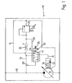
- Figure 1 is a schematic circuit diagram of one embodiment of the invention;
- Figure 2 is a cross-sectional view of apparatus according to the circuit of Figure 1;
- Figure 3 is a cross-sectional view of a second embodiment of the invention, showing modifications from the Figure 2 arrangement; and
- Figure 4 is a schematic representation of part of the circuit of Figure 1, in greater detail.
- In the following description, the invention is described with reference to an hydraulic control circuit although it is possible to devise embodiments of the invention employing fluids other than hydraulic oil.
- Referring to the drawings, there is shown an
hydraulic control circuit 10 according to the invention. -
Circuit 10 includes avariable outlet pump 11 capable of supplying fluid at outlet pressure vialine 12 for use in a load (not shown). - The outlet pressure of
pump 11 is controlled by an adjuster in the form ofcontrol piston 13.Control piston 13 is biassed by aspring 14 to a position of minimum extension.Control piston 13 is such that as it extends towardspump 11 it causes a reduction in the outlet pressure inline 12. This is achieved eg. by a linkage directly or indirectly interconnectingpiston 13 and the yoke ofpump 11. This is shown schematically in Figure 4. In practical embodiments,spring 14 lies within thehousing 11 to allow for draining of the left hand side ofcontrol piston 13. The casing ofpump 11 is connected to drain in a per se known manner. -
Circuit 10 includes a conventional, solenoid actuated,proportional control valve 16 arranged to supply fluid at control pressure in the circuit, in dependence on the setting of eg. a lever or dial operatively connected to the solenoid thereof. -
Circuit 10 also includes a proportional, pressure actuated, directional controller in the form ofpressure compensator 17. -
Pressure compensator 17 includes a moveable spool 18 (Figures 2 and 3) that in a first position connects the inlet side ofcontrol piston 13 to tank via drain line D and in a second position connects the inlet side ofcontrol piston 13 to fluid at outlet pressure tapped fromline 12 vialine 19. -
Pressure compensator 17 includes apiston 20 that is reciprocable in a bore 22 (Figures 2 and 3) adjacent abore 23 in whichspool 18 is longitudinally slidable. Bore 23 is open endedadjacent bore 22, and afree end 24 ofspool 18 protrudes beyond the end ofbore 23 for engagement with the left hand side ofpiston 20 as shown in the drawing figures.Free end 24 andpiston 20 are in mutual engagement with one another but are not secured together in the preferred embodiment. - Piston 20 is biassed towards the left hand side of the drawing figures by a resilient biassing means in the form of
spring 25 acting longitudinally inbore 22. - Fluid at control pressure is supplied from
control valve 16 via line -26 to the left hand side ofpiston 20. In other words, fluid at control pressure in the circuit tends to oppose the biassing effect ofspring 25 onpiston 20. - An
adjustable screw 40 may be used as desired to alter the force provided byspring 25. This determines the pressure required atline 29 to cause movement ofpiston 20 as described below. -
Spool 18 includes aplate 28 the left hand side. of which in the drawing figures is supplied with fluid at outlet pressure vialine 29. Thus, when thefree end 24 ofspool 18 is in contact with the left hand side ofpiston 20, fluid at outlet pressure acting onplate 28 also tends to overcome the biassing effect ofspring 25. The bias would otherwise drivepiston 20 andspool 18 to the left of the drawing figures. -
Plate 28 serves as a valve member for connectingline 19 to the inlet side ofpiston 13, thereby supplying the inlet side ofpiston 13 with fluid at outlet pressure. This is achieved by virtue ofplate 28 blockingaperture 30 to line 31 (which feeds the inlet side of piston 13) when thespool 18 is biased to is extreme left hand position as shown in eg. Figure 2. -
Spool 18 shown in the drawings is of a per se known design. Any of a number of equivalent devices may be employed, if appropriate, as alternatives to spool 18. - The circuit is arranged to provide maximum pump output pressure if the electrical supply to the solenoid actuated
proportional control valve 16 is lost or corrupted. This is the inverse of normal control modes, and is achieved via the following operational sequence: - When there is no fluid at control pressure in the circuit, eg. because the
control valve 16 is set to zero or because the electrical power thereto has failed,piston 20 is biased to its left hand position (maximum extension) by virtue ofspring 25. This setspressure compensator 17 to the configuration shown in Figure 1, ie. so that the inlet side ofpiston 13 is connected to tank via drain line D, and the supply of fluid at outlet pressure vialine 19 is blocked. Sincepiston 13 is connected to tank,spring 14causes piston 13 to retract fully thereby giving rise to a maximum output pressure in thepump 11. When the output pressure reaches its maximum, the pump flow adjusts according to the load requirement. - As the pressure in
line 12 increases (with increasing loading of the pump 11), the outlet pressure inline 29 also increases until the force acting onplate 28 overcomes the force provided byspring 25 which acts, viapiston 20, against thefree end 24 ofspool 18. Consequently,spool 18 moves to the right of Figure 1, connectingline 19 to the inlet side ofpiston 13, and supplying fluid at outlet pressure thereto. This causes extension ofpiston 13 againstspring 14. This in turn causes a reduction in the pump output pressure. - If the loading on
pump 11 decreases, the reverse sequence occurs to retractpiston 13 and thereby increase the pump output pressure. Thus, the circuit functions as a regulator of the pump output. The circuit supplies a regulated output at all times, regardless of whether there is electrical power for thecontrol valve 16. - When power is supplied to the
control valve 16, fluid at control pressure is applied to the left hand side ofpiston 20 vialine 26. This acts against the force ofspring 25, with the result that outlet pressure inline 29 is sufficient to movespool 18 to the right, thereby connecting outlet pressure inline 19 to the inlet side ofpiston 13. This again causes extension ofpiston 13, thereby reducing the pump output. Thus it is possible to reduce the pump output from its regulated maximum by a predetermined amount according to the setting of the proportional control ofvalve 16. - When
control valve 16 is configured as a proportional valve, it includes or is operatively associated with aconstant flow valve 32 necessary to stabilise the flow to it. - As mentioned hereinabove, the control action of the preferred circuit could be inverted eg. by the use of a different form of
control piston 13 that is biased in the opposite direction and in which fluid at outlet pressure acts to retract rather than extend the piston. - Figures 2 and 3 show practical embodiments of the invention. In the Figure 2 embodiment, the side of
piston 20adjacent spring 25 is connected to tank vialine 34. This ensures that the fluid pressures opposing the action ofspring 25 do not have to accommodate (uncalibrated) pressures caused by compression of fluid on the right hand side ofpiston 20. - Also, the portion of
bore 23 to the right ofplate 28 is connected to drain line D. This allowsspool 18 toopen line 31 to drain when there is no pressure in thepump 11. Thevalve 16 of Figure 2 is a proportional control valve. The end of thespool 15 constantly receives fluid fromvalve 32, and counteracts it. Thus the control pressure arises inline 26, in dependence on the solenoid force invalve 16 and the pin area over which such pressure acts. - The embodiment of Figure 3 is similar to that of Figure 2, except that it employs a pressure reducing valve, instead of the proportional control valve of Figure 2.
- In the pressure reducing valve, the controlled pressure acts on the end of the
spool 15, against the solenoid force. If the pressure is insufficient to counter the solenoid force, thespool 15 moves to the left in Figure 3 and vialine 21 connects the pump outlet to the left hand side ofpiston 20. Pump output pressure is also supplied to the end ofspool 15 via suitable drilled holes. - As the pump output pressure grows, in accordance with the operational sequence described above, it balances the solenoid force so that
spool 15 closes. This maintains the pressure at the left hand side ofpiston 20, so that the circuit is balanced. - If the pump output pressure exceeds the solenoid force, the
spool 15 moves to allow the controlled pressure to drain to tank, vialine 19, until a new balance is achieved. -
Valve 32 is not needed in the Figure 3 embodiment. - As is evident from Figures 2 and 3, a circuit according to the invention may readily be manufactured as a compact device in which only the pump,
control piston 13 and load are external to acommon housing 35. - The circuit of the invention may be configured in numerous ways. For example, in some embodiments the
piston 20 could be dispensed with as a separate item, and could instead be formed integrally withspool 18. - Also, the
control valve 16 need not necessarily be a solenoid actuated valve.
Claims (12)
- A fluid power control circuit, comprising:a pump, connectable to supply fluid at outlet pressure to a load;an adjustable control device capable of supplying control fluid in the circuit;a fluid-actuated adjuster for adjusting the output of the pump; anda pressure-actuated directional controller for operatively supplying fluid at outlet pressure to the adjuster, wherein:whereby fluid at outlet pressure is supplied to the adjuster when the aggregate effect of fluid at outlet pressure and control fluid on the directional controller exceeds its bias.i) the directional controller is biassed to disconnect fluid at outlet pressure from the adjuster;ii) fluid at outlet pressure acts on the directional controller to counter said bias; andiii) control fluid in the circuit acts on the directional controller to counter said bias,
- A circuit according to Claim 1 wherein the supply of fluid at outlet pressure to the fluid-actuated adjuster causes the adjuster to decrease the outlet pressure of the pump.
- A circuit according to Claim 1 or Claim 2 wherein the directional controller is a pressure compensator including a moveable spool.
- A circuit according to Claim 3 including resilient biassing means biassing the spool to disconnect the fluid at outlet pressure from the adjuster.
- A circuit according to Claim 3 or Claim 4 wherein fluid at outlet pressure acts on the spool against the bias of the directional controller to disconnect fluid at outlet pressure from the adjuster.
- A circuit according to any of Claims 3 to 5 wherein the directional controller includes a first, moveable surface against which control fluid in the circuit may act against the bias of the directional controller to disconnect fluid at outlet pressure from the adjuster, the moveable surface being drivingly engageable with the spool.
- A circuit according to Claim 6 when dependent from Claim 4 wherein the directional controller includes a moveable piston defining the first, moveable surface at one side thereof, the said side of the piston being drivingly engageable with the spool; and the resilient biassing means acting on the opposite side of the piston.
- A circuit according to Claim 5 or any claim dependent therefrom wherein the spool includes a further surface against which acts fluid at outlet pressure.
- A circuit according to any preceding claim wherein the control device is a proportional control valve.
- A circuit according to any preceding claim wherein the directional controller is a proportional device.
- A pressure control apparatus including a circuit according to any preceding claim.
- An apparatus according to Claim 10 when configured as a fan or pump motor control apparatus.
Applications Claiming Priority (2)
| Application Number | Priority Date | Filing Date | Title |
|---|---|---|---|
| GB9606186 | 1996-03-22 | ||
| GB9606186A GB2311385B (en) | 1996-03-23 | 1996-03-23 | A fluid power control circuit |
Publications (3)
| Publication Number | Publication Date |
|---|---|
| EP0797009A2 true EP0797009A2 (en) | 1997-09-24 |
| EP0797009A3 EP0797009A3 (en) | 1999-06-23 |
| EP0797009B1 EP0797009B1 (en) | 2003-05-07 |
Family
ID=10790943
Family Applications (1)
| Application Number | Title | Priority Date | Filing Date |
|---|---|---|---|
| EP97301718A Expired - Lifetime EP0797009B1 (en) | 1996-03-22 | 1997-03-13 | A fluid power control circuit |
Country Status (5)
| Country | Link |
|---|---|
| US (1) | US5884480A (en) |
| EP (1) | EP0797009B1 (en) |
| DE (1) | DE69721622T2 (en) |
| ES (1) | ES2197303T3 (en) |
| GB (1) | GB2311385B (en) |
Cited By (1)
| Publication number | Priority date | Publication date | Assignee | Title |
|---|---|---|---|---|
| CN103477093B (en) * | 2011-04-18 | 2015-11-25 | 西门子公司 | electropneumatic position regulator |
Families Citing this family (7)
| Publication number | Priority date | Publication date | Assignee | Title |
|---|---|---|---|---|
| DE102005016181B4 (en) * | 2005-04-08 | 2018-05-09 | Robert Bosch Automotive Steering Gmbh | Regulating device for a hydraulic conveyor |
| KR100641396B1 (en) * | 2005-09-15 | 2006-11-01 | 볼보 컨스트럭션 이키프먼트 홀딩 스웨덴 에이비 | Hydraulic control system |
| US9803637B2 (en) * | 2011-07-14 | 2017-10-31 | Ford Global Technologies, Llc | Variable displacement hydraulic pump control |
| US9091040B2 (en) | 2012-08-01 | 2015-07-28 | Caterpillar Inc. | Hydraulic circuit control |
| CN108026989B (en) * | 2015-09-29 | 2020-05-15 | 舍弗勒技术股份两合公司 | Fluid assembly |
| US10330126B2 (en) | 2016-12-16 | 2019-06-25 | Caterpillar Inc. | Fan control system with electro-hydraulic valve providing three fan motor operational positions |
| US12534879B1 (en) * | 2024-07-24 | 2026-01-27 | Caterpillar Inc. | Hydraulic pump with de-stroke control |
Family Cites Families (14)
| Publication number | Priority date | Publication date | Assignee | Title |
|---|---|---|---|---|
| DE3118576A1 (en) * | 1981-05-11 | 1982-12-02 | Mannesmann Rexroth GmbH, 8770 Lohr | CONTROL DEVICE FOR A PUMP |
| US4665699A (en) * | 1981-11-24 | 1987-05-19 | Linde Aktiengesellschaft | Hydrostatic drives |
| DE3340332C2 (en) * | 1983-11-08 | 1988-11-10 | Hydromatik GmbH, 7915 Elchingen | Power control device for a hydrostatic drive with flow rate adjustment |
| DE3581539D1 (en) * | 1985-08-17 | 1991-02-28 | Vickers Systems Gmbh | DRIVE TORQUE CONTROL DEVICE. |
| US4801247A (en) * | 1985-09-02 | 1989-01-31 | Yuken Kogyo Kabushiki Kaisha | Variable displacement piston pump |
| DE3535771A1 (en) * | 1985-10-07 | 1987-04-09 | Linde Ag | HYDROSTATIC DRIVE WITH SEVERAL CONSUMERS |
| CA1278978C (en) * | 1987-02-19 | 1991-01-15 | Lary Lynn Williams | Hydraulic system for an industrial machine |
| JP2622401B2 (en) * | 1988-06-10 | 1997-06-18 | 東芝機械株式会社 | Hydraulic flow control device |
| JPH0374605A (en) * | 1989-08-16 | 1991-03-29 | Komatsu Ltd | Pressure oil feeder for working machine cylinder |
| DE3929466A1 (en) * | 1989-09-05 | 1991-03-21 | Rexroth Mannesmann Gmbh | CONTROL CIRCUIT FOR A HYDRAULIC POWER LIFT OPERATED WITH A PUMP |
| KR950007252B1 (en) * | 1991-11-30 | 1995-07-07 | 삼성중공업주식회사 | Control device of variable displacement hydraulic pump |
| JPH06137276A (en) * | 1992-10-29 | 1994-05-17 | Komatsu Ltd | Variable capacity hydraulic pump capacity controller |
| GB2291987B (en) * | 1993-03-26 | 1997-04-02 | Komatsu Mfg Co Ltd | Controller for hydraulic drive machine |
| KR0120281B1 (en) * | 1994-07-29 | 1997-10-22 | 석진철 | Pump input horsepower and flow control device of load sensing system |
-
1996
- 1996-03-23 GB GB9606186A patent/GB2311385B/en not_active Expired - Lifetime
-
1997
- 1997-03-13 EP EP97301718A patent/EP0797009B1/en not_active Expired - Lifetime
- 1997-03-13 DE DE69721622T patent/DE69721622T2/en not_active Expired - Lifetime
- 1997-03-13 ES ES97301718T patent/ES2197303T3/en not_active Expired - Lifetime
- 1997-03-21 US US08/822,454 patent/US5884480A/en not_active Expired - Lifetime
Cited By (1)
| Publication number | Priority date | Publication date | Assignee | Title |
|---|---|---|---|---|
| CN103477093B (en) * | 2011-04-18 | 2015-11-25 | 西门子公司 | electropneumatic position regulator |
Also Published As
| Publication number | Publication date |
|---|---|
| DE69721622D1 (en) | 2003-06-12 |
| GB9606186D0 (en) | 1996-05-29 |
| EP0797009B1 (en) | 2003-05-07 |
| GB2311385B (en) | 2000-07-19 |
| US5884480A (en) | 1999-03-23 |
| DE69721622T2 (en) | 2004-02-19 |
| GB2311385A (en) | 1997-09-24 |
| EP0797009A3 (en) | 1999-06-23 |
| ES2197303T3 (en) | 2004-01-01 |
Similar Documents
| Publication | Publication Date | Title |
|---|---|---|
| EP2668379B1 (en) | Oil pump with selectable outlet pressure | |
| US8496445B2 (en) | Control system and method for pump output pressure control | |
| EP1706639B1 (en) | Two-stage pressure relief valve | |
| EP0468944A1 (en) | An arrangement for controlling hydraulic motors | |
| US5421705A (en) | Overload protective device for an internal combustion engine acting as a drive motor of a main pump of a hydraulic pressure generator | |
| US4738102A (en) | Hydrostatic drives | |
| US5884480A (en) | Fluid power control circuit | |
| JPH09126139A (en) | Capacity controller for variable displacement pump | |
| US4518321A (en) | Power regulation device for a hydraulic pump | |
| US4119016A (en) | Hydraulic control device | |
| EP2034380B1 (en) | Electrically controlled pilot operated pressure regulator valve apparatus and method of operation of the same. | |
| CN111075702B (en) | Load-sensitive hydraulic system with hydraulic adjusting device | |
| US4967554A (en) | Commonly-piloted directional control valve and load pressure signal line relieving switching valve | |
| US4715788A (en) | Servo control variable displacement pressure compensated pump | |
| EP0015069B1 (en) | Fluid actuated constant output power control for variable delivery pump | |
| US4723409A (en) | Safety circuit for a hydraulic system | |
| EP0359695B1 (en) | Automatic control for variable displacement pump | |
| CN101321953B (en) | Feed pump | |
| US20050160904A1 (en) | Anti-stall pilot pressure control system for open center systems | |
| US4777797A (en) | Hydraulic system with suction maintenance of its control pump | |
| US20040208754A1 (en) | Speed regulated oil delivery system | |
| US3601504A (en) | Compensator and pressure limiting device | |
| US4152896A (en) | Hydraulic power system with a load-sensing and a cutoff control valve | |
| KR101740925B1 (en) | Hydraulic assembly comprising a variable displacement pump and a relief valve | |
| US6089248A (en) | Load sense pressure controller |
Legal Events
| Date | Code | Title | Description |
|---|---|---|---|
| PUAI | Public reference made under article 153(3) epc to a published international application that has entered the european phase |
Free format text: ORIGINAL CODE: 0009012 |
|
| AK | Designated contracting states |
Kind code of ref document: A2 Designated state(s): DE ES FR GB IT NL SE |
|
| ITCL | It: translation for ep claims filed |
Representative=s name: JACOBACCI CASETTA & PERANI S.P.A. |
|
| PUAL | Search report despatched |
Free format text: ORIGINAL CODE: 0009013 |
|
| AK | Designated contracting states |
Kind code of ref document: A3 Designated state(s): DE ES FR GB IT NL SE |
|
| 17P | Request for examination filed |
Effective date: 19990724 |
|
| GRAG | Despatch of communication of intention to grant |
Free format text: ORIGINAL CODE: EPIDOS AGRA |
|
| 17Q | First examination report despatched |
Effective date: 20020618 |
|
| GRAG | Despatch of communication of intention to grant |
Free format text: ORIGINAL CODE: EPIDOS AGRA |
|
| GRAH | Despatch of communication of intention to grant a patent |
Free format text: ORIGINAL CODE: EPIDOS IGRA |
|
| GRAH | Despatch of communication of intention to grant a patent |
Free format text: ORIGINAL CODE: EPIDOS IGRA |
|
| GRAA | (expected) grant |
Free format text: ORIGINAL CODE: 0009210 |
|
| AK | Designated contracting states |
Designated state(s): DE ES FR GB IT NL SE |
|
| REG | Reference to a national code |
Ref country code: GB Ref legal event code: FG4D |
|
| REG | Reference to a national code |
Ref country code: SE Ref legal event code: TRGR |
|
| REF | Corresponds to: |
Ref document number: 69721622 Country of ref document: DE Date of ref document: 20030612 Kind code of ref document: P |
|
| REG | Reference to a national code |
Ref country code: ES Ref legal event code: FG2A Ref document number: 2197303 Country of ref document: ES Kind code of ref document: T3 |
|
| ET | Fr: translation filed | ||
| PLBE | No opposition filed within time limit |
Free format text: ORIGINAL CODE: 0009261 |
|
| STAA | Information on the status of an ep patent application or granted ep patent |
Free format text: STATUS: NO OPPOSITION FILED WITHIN TIME LIMIT |
|
| 26N | No opposition filed |
Effective date: 20040210 |
|
| REG | Reference to a national code |
Ref country code: FR Ref legal event code: PLFP Year of fee payment: 20 |
|
| PGFP | Annual fee paid to national office [announced via postgrant information from national office to epo] |
Ref country code: IT Payment date: 20160311 Year of fee payment: 20 Ref country code: NL Payment date: 20160307 Year of fee payment: 20 Ref country code: ES Payment date: 20160315 Year of fee payment: 20 |
|
| PGFP | Annual fee paid to national office [announced via postgrant information from national office to epo] |
Ref country code: FR Payment date: 20160223 Year of fee payment: 20 Ref country code: GB Payment date: 20160224 Year of fee payment: 20 Ref country code: SE Payment date: 20160307 Year of fee payment: 20 |
|
| PGFP | Annual fee paid to national office [announced via postgrant information from national office to epo] |
Ref country code: DE Payment date: 20160324 Year of fee payment: 20 |
|
| REG | Reference to a national code |
Ref country code: DE Ref legal event code: R071 Ref document number: 69721622 Country of ref document: DE |
|
| REG | Reference to a national code |
Ref country code: NL Ref legal event code: MK Effective date: 20170312 |
|
| REG | Reference to a national code |
Ref country code: GB Ref legal event code: PE20 Expiry date: 20170312 |
|
| REG | Reference to a national code |
Ref country code: SE Ref legal event code: EUG |
|
| PG25 | Lapsed in a contracting state [announced via postgrant information from national office to epo] |
Ref country code: GB Free format text: LAPSE BECAUSE OF EXPIRATION OF PROTECTION Effective date: 20170312 |
|
| REG | Reference to a national code |
Ref country code: ES Ref legal event code: FD2A Effective date: 20170626 |
|
| PG25 | Lapsed in a contracting state [announced via postgrant information from national office to epo] |
Ref country code: ES Free format text: LAPSE BECAUSE OF EXPIRATION OF PROTECTION Effective date: 20170314 |