EP0797032B1 - Vanne et son procédé de fabrication - Google Patents
Vanne et son procédé de fabrication Download PDFInfo
- Publication number
- EP0797032B1 EP0797032B1 EP97104566A EP97104566A EP0797032B1 EP 0797032 B1 EP0797032 B1 EP 0797032B1 EP 97104566 A EP97104566 A EP 97104566A EP 97104566 A EP97104566 A EP 97104566A EP 0797032 B1 EP0797032 B1 EP 0797032B1
- Authority
- EP
- European Patent Office
- Prior art keywords
- valve
- carrier
- closing body
- ring
- annular
- Prior art date
- Legal status (The legal status is an assumption and is not a legal conclusion. Google has not performed a legal analysis and makes no representation as to the accuracy of the status listed.)
- Expired - Lifetime
Links
Images
Classifications
-
- F—MECHANICAL ENGINEERING; LIGHTING; HEATING; WEAPONS; BLASTING
- F16—ENGINEERING ELEMENTS AND UNITS; GENERAL MEASURES FOR PRODUCING AND MAINTAINING EFFECTIVE FUNCTIONING OF MACHINES OR INSTALLATIONS; THERMAL INSULATION IN GENERAL
- F16J—PISTONS; CYLINDERS; SEALINGS
- F16J15/00—Sealings
- F16J15/02—Sealings between relatively-stationary surfaces
- F16J15/021—Sealings between relatively-stationary surfaces with elastic packing
- F16J15/022—Sealings between relatively-stationary surfaces with elastic packing characterised by structure or material
-
- F—MECHANICAL ENGINEERING; LIGHTING; HEATING; WEAPONS; BLASTING
- F16—ENGINEERING ELEMENTS AND UNITS; GENERAL MEASURES FOR PRODUCING AND MAINTAINING EFFECTIVE FUNCTIONING OF MACHINES OR INSTALLATIONS; THERMAL INSULATION IN GENERAL
- F16J—PISTONS; CYLINDERS; SEALINGS
- F16J15/00—Sealings
- F16J15/02—Sealings between relatively-stationary surfaces
- F16J15/021—Sealings between relatively-stationary surfaces with elastic packing
- F16J15/022—Sealings between relatively-stationary surfaces with elastic packing characterised by structure or material
- F16J15/024—Sealings between relatively-stationary surfaces with elastic packing characterised by structure or material the packing being locally weakened in order to increase elasticity
-
- F—MECHANICAL ENGINEERING; LIGHTING; HEATING; WEAPONS; BLASTING
- F16—ENGINEERING ELEMENTS AND UNITS; GENERAL MEASURES FOR PRODUCING AND MAINTAINING EFFECTIVE FUNCTIONING OF MACHINES OR INSTALLATIONS; THERMAL INSULATION IN GENERAL
- F16J—PISTONS; CYLINDERS; SEALINGS
- F16J15/00—Sealings
- F16J15/02—Sealings between relatively-stationary surfaces
- F16J15/06—Sealings between relatively-stationary surfaces with solid packing compressed between sealing surfaces
- F16J15/061—Sealings between relatively-stationary surfaces with solid packing compressed between sealing surfaces with positioning means
-
- F—MECHANICAL ENGINEERING; LIGHTING; HEATING; WEAPONS; BLASTING
- F16—ENGINEERING ELEMENTS AND UNITS; GENERAL MEASURES FOR PRODUCING AND MAINTAINING EFFECTIVE FUNCTIONING OF MACHINES OR INSTALLATIONS; THERMAL INSULATION IN GENERAL
- F16K—VALVES; TAPS; COCKS; ACTUATING-FLOATS; DEVICES FOR VENTING OR AERATING
- F16K1/00—Lift valves or globe valves, i.e. cut-off apparatus with closure members having at least a component of their opening and closing motion perpendicular to the closing faces
- F16K1/32—Details
- F16K1/34—Cutting-off parts, e.g. valve members, seats
- F16K1/42—Valve seats
- F16K1/425—Attachment of the seat to the housing by plastical deformation, e.g. valve seat or housing being plastically deformed during mounting
Definitions
- DE-A 23 46 332 shows a seal for the closure of a pressure vessel with the help of a Metal ring, which has a groove-shaped recess on one end into which a ring-shaped counterpart rounded at the front is pressed in so that the Leg of the metal ring with its outer sides radially against circumferential sealing surfaces of the Housing pressed. Limiting by the axial movement of the counterpart Stops ensure that the deformation of the metal ring in the elastic range remains.
- valve seals Very low lift valves.
- EP-A 0 588 570 a valve according to the features of the preamble of claim 1 is known, the disc-shaped closing body a piezoelectrically deformable, in its central part Plate is rigidly supported, the edges of which are ring-shaped, the valve passage surrounding valve seal cooperate.
- a two-spring system described in which one spring remains when the valve is first closed deformed and fixed in this deformed shape while the second spring during later operation for the elastic seal between the valve seat and the closing body worries.
- the second spring from an O-ring while the first spring by V-shaped slanted leg plates is formed, the spread free ends of which are on the flat surface of the valve seat support and wear the O-ring on the other side.
- the result is a V-shaped Structure whose apex is formed by the O-ring, while the leg ends on the Fit the valve seat.
- the invention proposes that in claim 1 Marked design of the support surfaces for the leg ends. At a Curvature or beveling of the support surfaces of the carrier maintain the deformable Thigh ends have an additional degree of freedom in their movement, making them less intrinsic must be deformed itself and consequently the wave formation does not occur. So that's one permanent and tight sealing of the valve seal on the support with simple Funds guaranteed. If the legs rest on a circumferential rib of the wearer, then can be filled with a curable filler between the space Sealing ring, the legs and the carrier to a minimum, so that too any change in shape in the course of curing is greatly reduced or avoided. Further advantageous refinements of the invention result from the others Dependent claims.
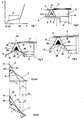
- the elastically deformable Sealing element 1 made of an elastomeric material, e.g. Rubber that acts as an o-ring on the Valve plate 2 is applied.
- This is deformed by a piezo disk 3, which is fixed to the housing is supported on a pin 10 passing through the valve passage 4.
- the O-ring 1 is with the help two circumferential legs 5 and 6 on a flat support surface 7 of the valve seat 8 supported.
- the two legs 5 and 6 spread at an angle b are on their Leg ends glued to the support surface 7.
- the space 9 between the two Thighs are filled with a curable adhesive.
- the disk bulges with it its outer edge for example 0.15 mm upwards and lifts off the O-ring 1, the elastic deformation is only about 0.05 mm.
- a passage annular gap is thus created of about 0.1 mm opening height.
- the O-ring 1 is only elastically deformed by approximately 0.05 mm.
- the compression spring mentioned can also be the upper power connection for the Form piezo plate 3, while the lower one is produced via pin 10.
- FIG 3 is the Cross-sectional support surface of the valve seat or support 8 for the leg ends 25, 26 bevelled roof-like and these ends 25 and 26 of the legs 15 and 16 lie on this beveled parts 17, 18 so that when pressing the first Valve seal on the carrier 8, the leg ends 25 and 26 dodge somewhat, whereby on the one hand the risk of wave formation is eliminated and on the other hand one over the whole Uniform support of the leg ends 25 and 26 on the carrier 8, 17, 18 is guaranteed.
- the curing can for example, thermally or by means of ultrasound or high-frequency radiation.
- leg ends 25 and 26 of the seated on the carrier Double leg ring 15, 16 corresponding to the inclination of the support surfaces 17, 18th are beveled.
- the apex of the double leg ring with the O-ring 1 is located above the ridge line 19 of the roof-shaped support surface 17, 18.
- the region 20 of the carrier 17, 18 between the leg ends 25 and 26 can be indicated be flat in itself.
- the O-ring 1 with its two circumferential legs 15 and 16 is made of rubber, for example.
- the angle of inclination b of the roof surfaces 6 and / or 7 compared to the plane of the valve seat is about 5 to 70 degrees.
- the carrier 8 is on the inside 17 as well as on the outside 18 inclined to the horizontal.
- the Tolerance compensation can suffice to incline only one of these two surfaces 17 and 18, respectively and leave the other flat.
- the support surface 27 of the valve seat 8 curved convexly towards the sealing ring 1, as a result of which the leg ends 25 are also located here and 26 as a further degree of freedom of movement, lateral evasion at the initial Squeezing the two-part seal results.
- the support surface could also be on the inside and / or the outside be concavely curved, as indicated by the broken line 29 in FIG. 4.
- the configuration of the annular valve seal according to the invention permits larger ones Tolerances between valve seat and closing body with regard to their height and flatness. Since the legs 15 and 16 in the arrangement according to Figures 3 to 4 much larger Tolerances can be bridged than in the prior art in the work area K 1 a much flatter rise and thus a better Constancy of the spring force than in the known valve seal according to FIG. 2.
- Figure 5a shows in position A the inner leg 6 in the tension-free Condition and in position C in the assembled, i.e. preloaded condition.
- Figure 5b shows the inner leg 16 in position B unloaded and in position D in the assembled and fixed state.
- the angle of inclination a2 of the leg 16 is in the arrangement according to the invention (Figure 5b) much less than the inclination angle a1 of Leg 6 in the prior art ( Figure 5a).
- This is also the sensitivity for Changes in height h decreased. If you take a height tolerance in both cases ie same size by the value h2, you can see that over this tolerance range Angle a2 changes less than angle a1.
- the construction 5b is much less sensitive to differences in height h than that known arrangement according to Figure 5a.
- valve seal is in each case from the valve seat 8 worn. It is obvious that they just as well provide for the closing body 2 and with a flat or any shaped valve seat could work together.
- the attachment the valve seal on the valve seat is due to the reduced mass of the Valve closing body cheaper, which is particularly the case with fast-working valves low stroke, in particular piezoelectrically controlled valves as advantageous turns out.
Landscapes
- Engineering & Computer Science (AREA)
- General Engineering & Computer Science (AREA)
- Mechanical Engineering (AREA)
- Lift Valve (AREA)
- Reciprocating Pumps (AREA)
- Fuel-Injection Apparatus (AREA)
Claims (7)
- Vanne, en particulier vanne à gaz, avec un siège de vanne en forme de joint d'étanchéité de vanne de forme annulaire et avec un corps de fermeture de vanne (2, 3) coopérant avec le siège de vanne, dans laquelle le joint d'étanchéité de vanne de forme annulaire présente une pièce d'étanchéité (1) de forme annulaire, déformable élastiquement en service et active dans la direction de levée du corps de fermeture de vanne (2, 3), ainsi que des pièces de soutien (15, 16) à deux branches, reliées à celle-ci, déformables de manière permanente sous l'action d'un effort initial, portant à leur sommet la pièce d'étanchéité élastiquement déformable (1), dans laquelle les pièces de soutien (15, 16) prennent appui par les extrémités des branches (25, 26) sur un support (8) et sont fixées à celui-ci, dans laquelle les pièces de soutien déformables (15, 16) sont également de forme annulaire, et dans laquelle l'espace (9) délimité par les pièces de soutien (15, 16) et le support (8) est rempli d'une masse de remplissage durcissable, caractérisée en ce qu'au moins une des faces d'appui (17, 18, 27, 29) pour les extrémités des branches (25, 26) du côté du support est inclinée d'un angle différent de 90° par rapport à la direction de levée du corps de fermeture de vanne (2, 3).
- Vanne suivant la revendication 1, caractérisée en ce que la face d'appui inclinée (27, 29) du support (8) est incurvée de façon convexe ou concave en direction de l'anneau d'étanchéité (1).
- Vanne suivant la revendication 1, caractérisée en ce que la face d'appui inclinée (17, 18) du support (8) est inclinée vers l'intérieur et/ou vers l'extérieur.
- Vanne suivant la revendication 3, caractérisée en ce que les faces d'appui (17, 18) sont inclinées vers les deux côtés en forme de toit et le sommet de l'anneau à deux branches (15, 16) se trouve au-dessus de la ligne de faíte (19) des faces d'appui en forme de toit (17, 18), en position ouverte de la vanne.
- Vanne suivant la revendication 3 ou 4, caractérisée en ce que l'angle d'inclinaison (b) des faces de support inclinées (17, 18) par rapport au plan du siège de vanne, est compris entre 5° et 70°, et vaut de préférence environ 30°.
- Vanne suivant la revendication 3, 4 ou 5, caractérisée en ce que les extrémités des branches (25, 26) de l'anneau à deux branches (15, 16) appuyées sur le support (8) sont biseautées de façon correspondante à l'inclinaison de la face de support (17, 18).
- Procédé pour fabriquer une vanne, en particulier une vanne à gaz, suivant l'une quelconque des revendications précédentes, dans lequel la vanne présente un siège de vanne en forme de joint d'étanchéité de forme annulaire et un corps de fermeture de vanne (2, 3) coopérant avec le siège de vanne, qui comporte les étapes suivantes:a)un élément d'étanchéité de forme annulaire, se composant d'un anneau élastomère (1) et de deux branches (15, 16) également continues, dressées sur l'anneau sous un angle aigu, est rempli d'un adhésif durcissable dans un espace (9) délimité par les branches (15, 16) ;b)l'élément d'étanchéité est alors appliqué par les extrémités (25, 26) de ses branches sur une face de support (17, 18; 27, 29) entourant un passage de vanne (4), laquelle est soit inclinée en forme de toit (17, 18) soit incurvée (27, 29) en direction du corps de fermeture de vanne (2, 3);c)le corps de fermeture de vanne (2, 3) est déformé par serrage et fixé de façon stationnaire à son point d'appui (10), la configuration des branches (15, 16) étant adaptée à la distance entre le siège de vanne (7) et le corps de fermeture (2, 3);d)l'adhésif est durci et ainsi les extrémités (25, 26) des branches sont en même temps collées à la face de support (17, 18; 27, 29).
Applications Claiming Priority (2)
| Application Number | Priority Date | Filing Date | Title |
|---|---|---|---|
| DE19611128A DE19611128B4 (de) | 1996-03-21 | 1996-03-21 | Ventildichtung sowie Verfahren zu deren Herstellung |
| DE19611128 | 1996-03-21 |
Publications (3)
| Publication Number | Publication Date |
|---|---|
| EP0797032A2 EP0797032A2 (fr) | 1997-09-24 |
| EP0797032A3 EP0797032A3 (fr) | 1998-12-23 |
| EP0797032B1 true EP0797032B1 (fr) | 2001-11-14 |
Family
ID=7788962
Family Applications (1)
| Application Number | Title | Priority Date | Filing Date |
|---|---|---|---|
| EP97104566A Expired - Lifetime EP0797032B1 (fr) | 1996-03-21 | 1997-03-18 | Vanne et son procédé de fabrication |
Country Status (2)
| Country | Link |
|---|---|
| EP (1) | EP0797032B1 (fr) |
| DE (2) | DE19611128B4 (fr) |
Families Citing this family (2)
| Publication number | Priority date | Publication date | Assignee | Title |
|---|---|---|---|---|
| DE19748263A1 (de) * | 1997-10-31 | 1999-05-06 | Nass Magnet Gmbh | Ventil |
| RU2206008C1 (ru) * | 2002-06-26 | 2003-06-10 | Проектно-конструкторский и технологический институт трубопроводной арматуры "Атомармпроект" | Седло запорного органа арматуры трубопроводной |
Family Cites Families (5)
| Publication number | Priority date | Publication date | Assignee | Title |
|---|---|---|---|---|
| DE71059C (de) * | CH. S. BAVIER in New-York, V. St. A., 32 Nassaustr | Flanschen- und Ventildichtung | ||
| DE328472C (de) * | 1919-12-10 | 1920-10-30 | Carl Wessel | Dichtungsring fuer Ventile |
| DE627735C (de) * | 1934-02-17 | 1936-03-21 | Ernst Zoltan Jausz | Befestigung von Dichtungsringen, insbesondere fuer Absperrorgane fuer Heiss- und Hochdruckdampf |
| DE2346332A1 (de) * | 1973-09-14 | 1975-03-27 | Babcock & Wilcox Ag | Dichtung fuer den verschluss eines druckbehaelters |
| GB2270735A (en) * | 1992-09-15 | 1994-03-23 | Adrian Michael Woodward | Flow control valves |
-
1996
- 1996-03-21 DE DE19611128A patent/DE19611128B4/de not_active Expired - Fee Related
-
1997
- 1997-03-18 DE DE59705321T patent/DE59705321D1/de not_active Expired - Fee Related
- 1997-03-18 EP EP97104566A patent/EP0797032B1/fr not_active Expired - Lifetime
Also Published As
| Publication number | Publication date |
|---|---|
| EP0797032A2 (fr) | 1997-09-24 |
| DE59705321D1 (de) | 2001-12-20 |
| DE19611128A1 (de) | 1997-09-25 |
| DE19611128B4 (de) | 2004-12-02 |
| EP0797032A3 (fr) | 1998-12-23 |
Similar Documents
| Publication | Publication Date | Title |
|---|---|---|
| DE69130317T2 (de) | Geneigte Spiralfelder mit in ihrer Länge vorgesehener Elastomerfüllung | |
| DE4115382C2 (de) | Hydraulischer Dämpfer | |
| DE2731015C2 (de) | Zweistufiges Drosselventil für die Bodenventilanordnung eines hydraulischen Schwingungsdämpfers | |
| DE3812477C2 (fr) | ||
| DE3712489C2 (de) | Sitzanordnung für einen Kugelhahn | |
| DE2312445A1 (de) | Unter druck stehender stossdaempfer.101509 | |
| DE112007001672B4 (de) | Aktuator | |
| DE2460275A1 (de) | Stoss- und schwingungsisolator | |
| DE102009054049A1 (de) | Nockenwellenverstellanordnung | |
| DE2427528A1 (de) | Drosselventil, insbesondere fuer einen kraftfahrzeug-kuehlwasserkreislauf | |
| DE3721558A1 (de) | Endverschluss fuer einen fluidzylinder | |
| DE69101825T2 (de) | Hydroelastisches Lager. | |
| DE3245926C2 (de) | Ringförmiger Ausbruchspreventer und ringförmige Packung für Ausbruchspreventer | |
| DE1292953B (de) | Kugelgelenk | |
| DE2206771A1 (de) | Hochdruckdichtung mit dem o-ring angepasster abstuetzflaeche und kantenbelastetem dichtring | |
| DE2424040C3 (de) | Kolben von Schwingungsdämpfern, insbesondere für Kraftfahrzeuge | |
| EP0367287B1 (fr) | Vanne à diaphragme avec une membrane élastique supportée par le couvercle de vanne | |
| EP0797032B1 (fr) | Vanne et son procédé de fabrication | |
| EP0656271A1 (fr) | Pivot, en particulier pour un guide d'essieu d'un véhicule à moteur | |
| WO2004036070A1 (fr) | Joint d'articulation spherique pour entrainements de vehicules | |
| DE2207806C2 (de) | Plattenventil für Kolbenverdichter | |
| DE7305670U (de) | Ventilklappe | |
| DE69627696T2 (de) | Scheibenbremsvorrichtung für kraftfahrzeuge | |
| EP0364407A2 (fr) | Dispositif d'étanchéité pour soupapes ou brides, notamment pour système de vide | |
| EP0544984B1 (fr) | Joint d'étanchéité à des éléments animés d'un mouvement alternatif |
Legal Events
| Date | Code | Title | Description |
|---|---|---|---|
| PUAI | Public reference made under article 153(3) epc to a published international application that has entered the european phase |
Free format text: ORIGINAL CODE: 0009012 |
|
| AK | Designated contracting states |
Kind code of ref document: A2 Designated state(s): DE FR GB IT NL |
|
| PUAL | Search report despatched |
Free format text: ORIGINAL CODE: 0009013 |
|
| AK | Designated contracting states |
Kind code of ref document: A3 Designated state(s): DE FR GB IT NL |
|
| 17P | Request for examination filed |
Effective date: 19981111 |
|
| 17Q | First examination report despatched |
Effective date: 20001113 |
|
| GRAG | Despatch of communication of intention to grant |
Free format text: ORIGINAL CODE: EPIDOS AGRA |
|
| GRAG | Despatch of communication of intention to grant |
Free format text: ORIGINAL CODE: EPIDOS AGRA |
|
| GRAH | Despatch of communication of intention to grant a patent |
Free format text: ORIGINAL CODE: EPIDOS IGRA |
|
| RTI1 | Title (correction) |
Free format text: VALVE AND ITS MANUFACTURING PROCESS |
|
| GRAH | Despatch of communication of intention to grant a patent |
Free format text: ORIGINAL CODE: EPIDOS IGRA |
|
| GRAA | (expected) grant |
Free format text: ORIGINAL CODE: 0009210 |
|
| AK | Designated contracting states |
Kind code of ref document: B1 Designated state(s): DE FR GB IT NL |
|
| REF | Corresponds to: |
Ref document number: 59705321 Country of ref document: DE Date of ref document: 20011220 |
|
| REG | Reference to a national code |
Ref country code: GB Ref legal event code: IF02 |
|
| GBT | Gb: translation of ep patent filed (gb section 77(6)(a)/1977) |
Effective date: 20020130 |
|
| PLBE | No opposition filed within time limit |
Free format text: ORIGINAL CODE: 0009261 |
|
| STAA | Information on the status of an ep patent application or granted ep patent |
Free format text: STATUS: NO OPPOSITION FILED WITHIN TIME LIMIT |
|
| 26N | No opposition filed | ||
| PGFP | Annual fee paid to national office [announced via postgrant information from national office to epo] |
Ref country code: FR Payment date: 20050302 Year of fee payment: 9 |
|
| PGFP | Annual fee paid to national office [announced via postgrant information from national office to epo] |
Ref country code: NL Payment date: 20060209 Year of fee payment: 10 |
|
| PGFP | Annual fee paid to national office [announced via postgrant information from national office to epo] |
Ref country code: DE Payment date: 20060330 Year of fee payment: 10 |
|
| PGFP | Annual fee paid to national office [announced via postgrant information from national office to epo] |
Ref country code: IT Payment date: 20060331 Year of fee payment: 10 |
|
| GBPC | Gb: european patent ceased through non-payment of renewal fee |
Effective date: 20070318 |
|
| NLV4 | Nl: lapsed or anulled due to non-payment of the annual fee |
Effective date: 20071001 |
|
| REG | Reference to a national code |
Ref country code: FR Ref legal event code: ST Effective date: 20071130 |
|
| PG25 | Lapsed in a contracting state [announced via postgrant information from national office to epo] |
Ref country code: NL Free format text: LAPSE BECAUSE OF NON-PAYMENT OF DUE FEES Effective date: 20071001 Ref country code: DE Free format text: LAPSE BECAUSE OF NON-PAYMENT OF DUE FEES Effective date: 20071002 |
|
| PG25 | Lapsed in a contracting state [announced via postgrant information from national office to epo] |
Ref country code: GB Free format text: LAPSE BECAUSE OF NON-PAYMENT OF DUE FEES Effective date: 20070318 |
|
| PG25 | Lapsed in a contracting state [announced via postgrant information from national office to epo] |
Ref country code: FR Free format text: LAPSE BECAUSE OF NON-PAYMENT OF DUE FEES Effective date: 20070402 |
|
| PG25 | Lapsed in a contracting state [announced via postgrant information from national office to epo] |
Ref country code: FR Free format text: LAPSE BECAUSE OF NON-PAYMENT OF DUE FEES Effective date: 20060331 |
|
| PGFP | Annual fee paid to national office [announced via postgrant information from national office to epo] |
Ref country code: GB Payment date: 20060206 Year of fee payment: 10 |
|
| PG25 | Lapsed in a contracting state [announced via postgrant information from national office to epo] |
Ref country code: IT Free format text: LAPSE BECAUSE OF NON-PAYMENT OF DUE FEES Effective date: 20070318 |