EP0797058A1 - Wärmetauscherplatte - Google Patents
Wärmetauscherplatte Download PDFInfo
- Publication number
- EP0797058A1 EP0797058A1 EP97104379A EP97104379A EP0797058A1 EP 0797058 A1 EP0797058 A1 EP 0797058A1 EP 97104379 A EP97104379 A EP 97104379A EP 97104379 A EP97104379 A EP 97104379A EP 0797058 A1 EP0797058 A1 EP 0797058A1
- Authority
- EP
- European Patent Office
- Prior art keywords
- plate
- heat
- wall
- fumes
- protrusions
- Prior art date
- Legal status (The legal status is an assumption and is not a legal conclusion. Google has not performed a legal analysis and makes no representation as to the accuracy of the status listed.)
- Withdrawn
Links
- 239000012530 fluid Substances 0.000 claims abstract description 25
- 239000003517 fume Substances 0.000 claims abstract description 19
- 230000013011 mating Effects 0.000 claims abstract description 4
- 238000012856 packing Methods 0.000 claims description 8
- 238000007789 sealing Methods 0.000 claims description 8
- 239000011810 insulating material Substances 0.000 claims description 3
- 239000011819 refractory material Substances 0.000 claims description 3
- 239000002184 metal Substances 0.000 abstract description 10
- 230000005540 biological transmission Effects 0.000 description 2
- 238000004140 cleaning Methods 0.000 description 2
- 239000007789 gas Substances 0.000 description 2
- 238000000926 separation method Methods 0.000 description 2
- 239000004071 soot Substances 0.000 description 2
- 239000000919 ceramic Substances 0.000 description 1
- 239000004020 conductor Substances 0.000 description 1
- 230000001419 dependent effect Effects 0.000 description 1
- 230000001627 detrimental effect Effects 0.000 description 1
- 238000007689 inspection Methods 0.000 description 1
- 239000003350 kerosene Substances 0.000 description 1
- 239000000463 material Substances 0.000 description 1
- 210000002268 wool Anatomy 0.000 description 1
Images

Classifications
-
- F—MECHANICAL ENGINEERING; LIGHTING; HEATING; WEAPONS; BLASTING
- F28—HEAT EXCHANGE IN GENERAL
- F28F—DETAILS OF HEAT-EXCHANGE AND HEAT-TRANSFER APPARATUS, OF GENERAL APPLICATION
- F28F3/00—Plate-like or laminated elements; Assemblies of plate-like or laminated elements
- F28F3/02—Elements or assemblies thereof with means for increasing heat-transfer area, e.g. with fins, with recesses, with corrugations
- F28F3/022—Elements or assemblies thereof with means for increasing heat-transfer area, e.g. with fins, with recesses, with corrugations the means being wires or pins
-
- F—MECHANICAL ENGINEERING; LIGHTING; HEATING; WEAPONS; BLASTING
- F24—HEATING; RANGES; VENTILATING
- F24H—FLUID HEATERS, e.g. WATER OR AIR HEATERS, HAVING HEAT-GENERATING MEANS, e.g. HEAT PUMPS, IN GENERAL
- F24H3/00—Air heaters
- F24H3/02—Air heaters with forced circulation
- F24H3/06—Air heaters with forced circulation the air being kept separate from the heating medium, e.g. using forced circulation of air over radiators
- F24H3/10—Air heaters with forced circulation the air being kept separate from the heating medium, e.g. using forced circulation of air over radiators by plates
- F24H3/105—Air heaters with forced circulation the air being kept separate from the heating medium, e.g. using forced circulation of air over radiators by plates using fluid fuel
-
- F—MECHANICAL ENGINEERING; LIGHTING; HEATING; WEAPONS; BLASTING
- F24—HEATING; RANGES; VENTILATING
- F24H—FLUID HEATERS, e.g. WATER OR AIR HEATERS, HAVING HEAT-GENERATING MEANS, e.g. HEAT PUMPS, IN GENERAL
- F24H9/00—Details
- F24H9/14—Arrangements for connecting different sections, e.g. in water heaters
-
- F—MECHANICAL ENGINEERING; LIGHTING; HEATING; WEAPONS; BLASTING
- F24—HEATING; RANGES; VENTILATING
- F24H—FLUID HEATERS, e.g. WATER OR AIR HEATERS, HAVING HEAT-GENERATING MEANS, e.g. HEAT PUMPS, IN GENERAL
- F24H9/00—Details
- F24H9/14—Arrangements for connecting different sections, e.g. in water heaters
- F24H9/146—Connecting elements of a heat exchanger
Definitions
- This invention concerns a heat exchanging plate as set forth in the main claim.
- the heat exchanging plate according to the invention is used in applications where an intense exchange of heat is required, in a limited space, between two fluids.
- a preferential but not limited application of the heat exchanging plate according to the invention is on the exchange walls of hot air generators.
- the heat exchanging plate according to the invention is used preferentially in heat generators fed by flame, such as for example gas burners, gas oil burners, kerosene burners or similar, where it is a particular problem to inspect and clean the soot from the end part of the conduit for the discharge of the fumes.
- flame such as for example gas burners, gas oil burners, kerosene burners or similar
- a very common case in practice is the transmission of heat between two areas through a wall, as for example happens in heat exchangers, where the maximum exchange of heat between two fluids is desired, in order to have high efficiency and reduced consumption.
- the walls of the exchangers have an increased surface, generally by means of ribs or fins, this being all the more important as the difference in temperature between the two fluids is reduced.
- Another disadvantage is that it is difficult to inspect and/or clean inside the heat exchangers known to the state of the art.
- the purpose of the invention is to obtain a heat exchanging plate which can achieve a high rate of heat exchange in a limited space and therefore reduce the bulk of the exchanger while at the same time removing a high quantity of heat.
- a further purpose of the invention is to enable the inside of the heat exchanger to be inspected and cleaned easily.
- a further purpose of the invention is to obtain the greatest efficiency possible of the heat exchange, regardless of the direction of the two fluids between which the heat is exchanged, and also regardless of the difference in temperature of the two fluids.
- a further purpose is to obviate the necessity for tortuous routes for the fluids, as they may draw the fumes less efficiently towards the chimney.
- the heat exchanging plate according to the invention can be applied in cases when it is necessary to exchange heat between two fluids, for example in correspondence with the fumes-air exchanging walls of hot air generators.
- the plate is associated with, but can be detached from, the walls and cooperates with a hole of a mating shape made in the exchange walls themselves.
- the heat exchanging plate according to the invention comprises a metal plate, advantageously of high heat conducting material, which has fins, pins, corrugations, grooves or other irregularities on its surface suitable to increase the surface for exchanging heat on at least one of its faces.
- the contour of the metal plate is variable depending on the application.
- At least the front face has, in a position adjacent to the perimeter edge, a flat band, without any fins, pins or other protrusions, which acts as a seating for a sealing packing.
- the plate may be connected to the wall of the heat exchanger in any way, for example by means of clamps, joints, etc.
- the plate must be fixed in such a way that the protrusions on one face, for example the fins, protrude into one fluid and the protrusions on the other face, for example the pins, protrude into the other fluid.
- the heat exchanging plate is attached with the connection elements and by interposing the sealing packing between the heat exchanging plate and the surface to which the plate is to be attached in such a way as to guarantee the hermetic separation of the two fluids.
- the heat exchanging plate according to the invention is particularly advantageous in applications in correspondence with the end part of the route followed by the fumes, both because at that point the difference in temperature between the adjacent fluids is less and therefore a greater heat exchange is needed, and also because it is the area where soot and dirt most accumulate.
- the plate can be removed, it is possible to carry out easy and rapid operations of inspection and cleaning.
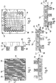
- FIGS 1 to 4 show a first type of the heat exchanging plate 10 according to the invention.
- the heat exchanging plate 10 is composed of a metal plate 11 with variable thickness, shape and dimensions according to the applications, advantageously of high heat conducting quality, defined by a rear surface 12 and a front surface 13.
- the metal plate 11 has, along its perimeter band, attachment holes 14 which serve to anchor the heat exchanging plate 10 onto a wall of the heat exchanger to which the plate 10 is associated.
- protrusions in this case shaped like fins 15, which cross longitudinally and parallelly the rear surface 12 in such a way as to stimulate the flow of the fluid which laps them.
- the fins 15 are substantially at right angles to the metal plate 11 and have a greater surface area at the base than at the top.
- protrusions On the forward surface 13, facing towards the inside of the heat generator, there are protrusions, arranged at right angles, in this case pins in the shape of truncated cones 16, the shape of which does not prevent the regular flow of the fluid which laps them.
- the protrusions shaped like truncated cone pins 16 are arranged to cover most of the forward surface 13 except for the perimeter area composed of a band without protrusions which acts as a seating for the sealing packing 17.
- Figure 5 shows the longitudinal section of the plate 10 according to the invention attached to a wall 18, for example the wall of a heat exchanger in a hot air generator.
- the wall 18 has a containing hole 19 of a shape mating with the perimeter contour of the metal plate 11 in such a way that the fins 15 on the rear surface 12 protrude into one fluid and the truncated cone pins 16 of the forward surface 13 protrude into the other fluid.
- the heat exchanging plate 10 is attached by interposing the sealing packing 17 between the metal plate 11 and the wall 18 in such a way as to guarantee the hermetic separation of the two fluids.
- Figure 6 shows a variant of Figure 5 where the metal plate 11 has a channel 20, which follows the perimeter contour of the plate and constitutes the containing seating for the sealing packing 17.
- Figure 7 shows an application of the invention in a fumes-air heat exchanger.
- a further advantage is given by the fact that the heat exchanging plate 10 can be easily removed from the wall 18 by acting on the connection elements associated with the attachment holes 14.
- This operation allows the inside areas defined by the wall 18 and the forward surface 13 to be inspected and cleaned, which would not otherwise be possible.
- Figure 8 shows an application of the invention in the final part of a heat exchanger for a hot air generator 21.
- Figure 9 shows a variant of Figure 8.
- the heat exchanging plate 10 is arranged at the front of a wall 22 lapped by fumes 25 on both sides.
- the fumes directed towards the outlet 23 yield their heat to the heat exchanging plate 10 but, at the same time, they receive heat from the wall 22 which is lapped by hot fumes on the other side.
- the wall 22 is covered on its inner surface near the outlet 23 with a suitable layer of refractory and insulating material 24.
- the layer of refractory and insulating material 24 can be made for example of ceramic wool or other suitable material.
- this layer 24 is attached and held on the wall 22 by means of suitable attaching and holding elements 27, for example metal sheet or mesh.
Landscapes
- Engineering & Computer Science (AREA)
- Physics & Mathematics (AREA)
- Thermal Sciences (AREA)
- Mechanical Engineering (AREA)
- General Engineering & Computer Science (AREA)
- Chemical & Material Sciences (AREA)
- Combustion & Propulsion (AREA)
- Heat-Exchange Devices With Radiators And Conduit Assemblies (AREA)
Applications Claiming Priority (2)
| Application Number | Priority Date | Filing Date | Title |
|---|---|---|---|
| IT96UD000037A IT1288867B1 (it) | 1996-03-22 | 1996-03-22 | Piastra scambiatrice di calore |
| ITUD960037 | 1996-03-22 |
Publications (1)
| Publication Number | Publication Date |
|---|---|
| EP0797058A1 true EP0797058A1 (de) | 1997-09-24 |
Family
ID=11422054
Family Applications (1)
| Application Number | Title | Priority Date | Filing Date |
|---|---|---|---|
| EP97104379A Withdrawn EP0797058A1 (de) | 1996-03-22 | 1997-03-14 | Wärmetauscherplatte |
Country Status (2)
| Country | Link |
|---|---|
| EP (1) | EP0797058A1 (de) |
| IT (1) | IT1288867B1 (de) |
Citations (3)
| Publication number | Priority date | Publication date | Assignee | Title |
|---|---|---|---|---|
| BE550812A (de) * | ||||
| GB529037A (en) * | 1939-04-11 | 1940-11-13 | Edwin Watkinson | Improvements in or relating to plate heat exchangers suitable for heating air |
| US3385356A (en) * | 1965-07-20 | 1968-05-28 | Dalin David | Heat exchanger with improved extended surface |
-
1996
- 1996-03-22 IT IT96UD000037A patent/IT1288867B1/it active IP Right Grant
-
1997
- 1997-03-14 EP EP97104379A patent/EP0797058A1/de not_active Withdrawn
Patent Citations (3)
| Publication number | Priority date | Publication date | Assignee | Title |
|---|---|---|---|---|
| BE550812A (de) * | ||||
| GB529037A (en) * | 1939-04-11 | 1940-11-13 | Edwin Watkinson | Improvements in or relating to plate heat exchangers suitable for heating air |
| US3385356A (en) * | 1965-07-20 | 1968-05-28 | Dalin David | Heat exchanger with improved extended surface |
Also Published As
| Publication number | Publication date |
|---|---|
| ITUD960037A0 (de) | 1996-03-22 |
| ITUD960037A1 (it) | 1997-09-22 |
| IT1288867B1 (it) | 1998-09-25 |
Similar Documents
| Publication | Publication Date | Title |
|---|---|---|
| US5671806A (en) | Charge air cooler | |
| US5775414A (en) | High temperature high pressure air-to-air heat exchangers and assemblies useful therein | |
| AU702645B2 (en) | Heat pipe heat exchanger tube sheet | |
| NL8402849A (nl) | Keramische recuperator. | |
| US2183956A (en) | Heat exchange apparatus | |
| US4224982A (en) | Tubular heat exchanger | |
| CS46092A3 (en) | Heat exchanger | |
| JPS58129187A (ja) | 工業用炉の壁および/またはア−チ構造部の冷却装置 | |
| US4617988A (en) | Soot blower for the removal of deposits from surfaces of heat exchangers or the like | |
| US4027654A (en) | Damper assembly for high temperature or corrosive gases | |
| EP1813884A2 (de) | Kondensationseinheit | |
| JPS60184591A (ja) | 対流式冷却器 | |
| JP3594606B2 (ja) | プレート型熱交換器 | |
| EP0277070B1 (de) | Rohrplatte eines Austauschers für einen thermischen Generator | |
| JPS61272590A (ja) | 生ガス・純ガス熱交換器 | |
| US5950616A (en) | High-efficiency waste oil fire heater | |
| EP0018745A1 (de) | Wärmeaustauscher | |
| JPS5813987A (ja) | 伝熱装置 | |
| SU1063792A1 (ru) | Устройство дл плавлени эмалей | |
| SU863982A1 (ru) | Устройство дл охлаждени плиты перекрыти ванны дуговой печи | |
| KR900008086Y1 (ko) | 채널형 리큐페레이터(Channel Type RecuPerator) | |
| WO1997021965A1 (en) | Lining of furnace | |
| RU2039317C1 (ru) | Котел-утилизатор | |
| JPS6129716Y2 (de) | ||
| SU992919A1 (ru) | Рекуператор |
Legal Events
| Date | Code | Title | Description |
|---|---|---|---|
| PUAI | Public reference made under article 153(3) epc to a published international application that has entered the european phase |
Free format text: ORIGINAL CODE: 0009012 |
|
| AK | Designated contracting states |
Kind code of ref document: A1 Designated state(s): AT BE CH DE DK ES FR GB IE IT LI NL PT SE |
|
| AX | Request for extension of the european patent |
Free format text: RO PAYMENT 970314;SI PAYMENT 970314 |
|
| 17P | Request for examination filed |
Effective date: 19980309 |
|
| 17Q | First examination report despatched |
Effective date: 19991018 |
|
| GRAG | Despatch of communication of intention to grant |
Free format text: ORIGINAL CODE: EPIDOS AGRA |
|
| RTI1 | Title (correction) |
Free format text: HEAT EXCHANGING WALL |
|
| GRAG | Despatch of communication of intention to grant |
Free format text: ORIGINAL CODE: EPIDOS AGRA |
|
| GRAG | Despatch of communication of intention to grant |
Free format text: ORIGINAL CODE: EPIDOS AGRA |
|
| GRAH | Despatch of communication of intention to grant a patent |
Free format text: ORIGINAL CODE: EPIDOS IGRA |
|
| STAA | Information on the status of an ep patent application or granted ep patent |
Free format text: STATUS: THE APPLICATION IS DEEMED TO BE WITHDRAWN |
|
| 18D | Application deemed to be withdrawn |
Effective date: 20021224 |