EP0797101A1 - Procédé et appareil pour détecter un défaut de raccordement électrique entre un connecteur et un câble blindé - Google Patents
Procédé et appareil pour détecter un défaut de raccordement électrique entre un connecteur et un câble blindé Download PDFInfo
- Publication number
- EP0797101A1 EP0797101A1 EP97420047A EP97420047A EP0797101A1 EP 0797101 A1 EP0797101 A1 EP 0797101A1 EP 97420047 A EP97420047 A EP 97420047A EP 97420047 A EP97420047 A EP 97420047A EP 0797101 A1 EP0797101 A1 EP 0797101A1
- Authority
- EP
- European Patent Office
- Prior art keywords
- cable
- shielding
- high frequency
- signal
- frequency signal
- Prior art date
- Legal status (The legal status is an assumption and is not a legal conclusion. Google has not performed a legal analysis and makes no representation as to the accuracy of the status listed.)
- Granted
Links
- 238000000034 method Methods 0.000 title claims description 21
- 230000003071 parasitic effect Effects 0.000 claims abstract description 23
- 230000005855 radiation Effects 0.000 claims abstract description 4
- 230000007547 defect Effects 0.000 claims description 13
- 238000001514 detection method Methods 0.000 claims description 8
- 238000002347 injection Methods 0.000 claims description 6
- 239000007924 injection Substances 0.000 claims description 6
- 230000003321 amplification Effects 0.000 claims 1
- 238000003199 nucleic acid amplification method Methods 0.000 claims 1
- 239000003990 capacitor Substances 0.000 abstract description 5
- 238000012216 screening Methods 0.000 abstract description 3
- 239000004065 semiconductor Substances 0.000 abstract description 2
- 239000004020 conductor Substances 0.000 description 8
- 244000045947 parasite Species 0.000 description 7
- 230000008878 coupling Effects 0.000 description 6
- 238000010168 coupling process Methods 0.000 description 6
- 238000005859 coupling reaction Methods 0.000 description 6
- 230000002950 deficient Effects 0.000 description 4
- 238000009434 installation Methods 0.000 description 4
- 238000012546 transfer Methods 0.000 description 4
- 238000012360 testing method Methods 0.000 description 3
- 230000005540 biological transmission Effects 0.000 description 2
- 238000012986 modification Methods 0.000 description 2
- 230000004048 modification Effects 0.000 description 2
- RYGMFSIKBFXOCR-UHFFFAOYSA-N Copper Chemical compound [Cu] RYGMFSIKBFXOCR-UHFFFAOYSA-N 0.000 description 1
- 229910052782 aluminium Inorganic materials 0.000 description 1
- XAGFODPZIPBFFR-UHFFFAOYSA-N aluminium Chemical compound [Al] XAGFODPZIPBFFR-UHFFFAOYSA-N 0.000 description 1
- 238000010276 construction Methods 0.000 description 1
- 229910052802 copper Inorganic materials 0.000 description 1
- 239000010949 copper Substances 0.000 description 1
- 238000010586 diagram Methods 0.000 description 1
- 238000007599 discharging Methods 0.000 description 1
- 230000005684 electric field Effects 0.000 description 1
- 230000001939 inductive effect Effects 0.000 description 1
- 230000007257 malfunction Effects 0.000 description 1
- 239000000463 material Substances 0.000 description 1
- 238000005259 measurement Methods 0.000 description 1
- 229910052751 metal Inorganic materials 0.000 description 1
- 239000002184 metal Substances 0.000 description 1
- 238000011084 recovery Methods 0.000 description 1
- 230000035945 sensitivity Effects 0.000 description 1
- 238000001228 spectrum Methods 0.000 description 1
Images

Classifications
-
- G—PHYSICS
- G01—MEASURING; TESTING
- G01R—MEASURING ELECTRIC VARIABLES; MEASURING MAGNETIC VARIABLES
- G01R31/00—Arrangements for testing electric properties; Arrangements for locating electric faults; Arrangements for electrical testing characterised by what is being tested not provided for elsewhere
- G01R31/50—Testing of electric apparatus, lines, cables or components for short-circuits, continuity, leakage current or incorrect line connections
- G01R31/58—Testing of lines, cables or conductors
Definitions
- the present invention relates to the technical field of the means used to test the quality of the shielding of an electrical circuit in the general sense.
- the object of the invention relates, more specifically, to the technical means used to detect a shielding fault in a circuit ensuring the transmission of data or information and consisting of shielded cables equipped with shielded connectors.
- the invention also aims more specifically to detect a connection fault between the shields of a cable and a connector.
- the shielding of these circuits is defective. Such a fault can come from a "wound" of the screen or from a fault in the electrical connection between the screen of the electrical connector and the screen of the cable.
- a shielding defect is likely to cause a malfunction of the IT installation due to its greater sensitivity to parasites.
- the computer installation can thus be disturbed by parasites constituted, for example, by rapid transients of the electrical supply, by electrostatic discharges, by a lightning magnetic field or a radiated field.
- the object of the invention therefore aims to remedy the drawbacks of prior techniques by proposing a method for measuring the transfer impedance or the attenuation factor of the shielding of a cable installed on site without modification of the installation, so as to determine its effectiveness in preventing the active wires of the cable from being subjected to the action of parasites.
- the object of the invention therefore aims to propose a method for detecting a shielding defect in a shielded cable mounted in a building which defines between itself and the shielding of the cable, a first parasitic capacitance.
- the method according to the invention thus makes it possible to measure the transfer impedance or the attenuation factor of the shielding of a cable installed on a site, at through an overall impedance formed by the series of the coupling impedance of the measuring device with respect to the building and the cable coupling impedance with respect to this same building.
- Another object of the invention is to propose a relatively simple implementation device making it possible to detect a shielding defect in a shielded cable mounted in a building which defines between the latter and the shielding of the cable, a first parasitic capacitance.
- Fig. 1 is a general view showing a detection device according to the invention intended for testing a shielded cable.
- Fig. 2 is a functional block diagram illustrating an embodiment of an apparatus according to the invention.
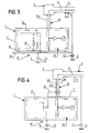
- FIGs. 3 and 4 illustrate two other alternative embodiments of an apparatus according to the invention.
- the subject of the invention relates to an apparatus 1 capable of detecting the quality of shielding of a shielded electrical circuit formed, in the example illustrated, by a shielded cable 2 in the general sense, equipped with a shielded electrical connector 3 .
- the shielded cable 2 is mounted inside a trough 4 forming part of a construction or a building 5 .
- Such a shielded circuit is part of a computer installation which is not shown and is intended for transmitting information or data.
- the cable shielded 2 can be of all types (coaxial, multipair, ...) and the shielding or "screening" carried out in different ways (copper braid, aluminum strip).
- the cable 2 has a core 2 1 and a shield 2 2 .
- the cable 2 is intended to be fitted with a connector 3 comprising a shield 3 2 intended to be connected to the shield 2 2 of the cable, and a recovery conductor 3 1 intended to be connected to the core 2 1 of the cable.
- the device 1 is intended to detect a shielding fault in circuit 2, 3 originating from a fault in the shielding of the cable and / or a defective connection between the shielded part 3 2 of the connector and the shielding 2 2 of the cable.
- the device 1 can be implemented whatever the type of connection used between the cable and the connector.
- the apparatus 1 comprises an accumulator 10 of continuous energy, preferably rechargeable, connected to a switching converter 11 also ensuring a rise in voltage.
- the converter 11 is connected, by means of a controlled switch 12, to a circuit 13 for producing a high frequency signal.
- the production circuit 13 is formed by a charge capacitor 14 connected by a resistor 15 to the controlled switch 12 and to a system 16 for discharging the capacitor 14 .
- the system 16 is of the gas or semiconductor type.
- the discharge system 16 is connected by a resistor 17 to a reference potential 18 to which the capacitor 14 is also placed.
- the reference voltage 18 is the zero voltage point of the apparatus which is advantageously connected to the casing or the casing 1 1 of the apparatus.
- the production circuit 13 delivers, via the discharge system 16 , a signal having a spectrum between 1 and 300 MHz and, preferably, between 5 and 15 MHz, and a voltage between 100 and 5000 Volts and, for example, around 500 Volts.
- the circuit 13 delivers a pulse signal with a repetition frequency of the order of 1/100 of a second.
- the circuit 13 can be adapted to deliver a signal of different shape, such as for example a sinusoidal signal having the frequency characteristics given above.
- the circuit 13 can work at constant current or at constant voltage.
- the circuit 13 is a voltage generator or, preferably, a current generator.
- the device 1 also comprises means 19 making it possible to ensure the return to the device of the high frequency signal circulating on the screen of the cable 2 .
- the means 19 are adapted to define a stray capacitance C 2 , called a second, between the measuring device 1 and the building 5 , so that the high frequency signal is able to circulate through the shielding of the cable 2 and the stray capacitances C 1 , C 2 and to return to the production circuit 13 .
- the means 19 are adapted so that the stray capacitance C 2 is defined between the building 5 and the production circuit 13 .
- the output circuit 13 is set to the reference potential 18 to which, preferably, frame or casing 1 1 of the apparatus 1 is also placed.
- the apparatus 1 also comprises a circuit 20 for detecting the level of a signal which is representative of a cable shielding defect.
- the detection circuit 20 is constituted, for example, by an amplifier 21 connected to a level indicator 22 , such as a galvanometer, a digital display or a bar graph.
- the input of the amplifier 21 is placed through a resistor 23 , at a reference potential which can be that of a structure or a housing 20 1 of the circuit 20 forming part of the device 1 .
- the implementation of the apparatus 1 according to the invention is carried out according to the following method.
- the measuring device 1 is placed and adapted so that a parasitic capacitance C 2 appears between the building 5 and the production circuit 13 .
- the apparatus 1 is placed on the floor of the building 5 and the casing 1 1 of the apparatus is set to the reference potential 18 to which is placed the output circuit 13.
- the device 1 is connected to the electrical connector 3 by means of a shielded connection cord 25 .
- the production system 13 is connected by the shield 25 2 of the cord, to the shield 3 2 of the connector, while the input of the detection circuit 20 is connected, by means of the core 25 1 of the cord 25 , at the hot spot 3 1 of the connector.
- the shield 25 2 of the cord 25 is connected to the housing 20 1 of the circuit 20 .
- the apparatus 1 is then controlled so that the production circuit 13 transmits a high frequency signal on the shields 3 2 , 2 2 of the connector 3 and of the cable 2 via the shield of the cord 25 .
- the return of the signal to the production system 13 is carried out through the two parasitic capacitors C 1 , C 2 placed in series.
- a defect in the cable shield or connection between the shield 3 2 of the connector 3 and the shield 2 2 of the cable 2 leads to the appearance, by radiation, of a signal on the core 2 1 of the cable and, consequently , at the input of the detection circuit 20.
- the level of the signal appearing on the core 2 1 , 3 1 is representative of the level of defectiveness of the shielding.
- the indicator 22 with or without memory makes it possible to display, in relation to a scale of defectiveness of the shielding, the level of the signal collected and, consequently, to know whether the shielding is defective.
- the method according to the invention thus makes it possible to detect the quality of a shielding by measuring the transfer impedance or the attenuation factor of the shielding.
- This measurement is carried out through an overall parasitic impedance which is in fact constituted by the serialization of the coupling impedance of the production circuit 13 relative to the building 5 and of the coupling impedance of the cable 2 relative to the building 5 .
- the detection carried out is reliable, insofar as these impedances vary little depending on the height of the cable and the material on which the cable and the device rest.
- the method is relatively easy to carry out, since it only requires the connection of the measuring device 1 to the electrical connector 3 .
- the high frequency signal is injected by the production circuit 13 on the cable shield, through the shield of the connection cord 25 .
- the return of this signal to the production circuit is ensured by the stray capacitances C 1 , C 2 .
- Fig. 3 illustrates another variant embodiment of the invention, according to which the high frequency signal is injected through the stray capacitance C 2 to return to the production circuit 13 , via the stray capacitance C 1 and the cable 2 .
- the means 19 for determining the second capacity C 2 are produced by means of a metal plate 30 on which the device 1 is mounted electrically isolated by feet 31 .
- the plate 30 is placed on a part of the building 5 and is connected to the output of the production circuit 13 .
- the parasitic capacitance C 2 therefore appears between the building 5 and the production circuit 13 via the plate 30 .
- the high frequency signal is therefore injected into the shield of the cable 2 via the plate 30 and the stray capacitances C 2 , C 1 .
- the return of the high frequency signal to the production circuit 13 is ensured by the shield 25 2 of the connection cord 25 , connected to the housing 1 1 of the device 1 , preferably placed at the reference potential 18 .
- Fig. 4 illustrates another embodiment of the invention according to which the coupling between the device 1 and the cable to be tested 2 is of an inductive nature.
- the production circuit 13 delivers its high frequency signal to the shield 25 2 of the connection cord 25 via a current clamp 33 .
- the means 19 for determining the second parasitic capacity are such that the parasitic capacity C 2 is determined between the building 5 and the shielding 25 2 of the connection cord 25 .
- the shield 25 2 of the cord 25 is connected to the housing 1 1 of the apparatus which defines the capacity C 2 relative to the building 5.
- the housing 1 1 creating the parasitic capacity C 2 can also be produced by means of a screened cable laid on the building 5 and the screen of which is connected to the screen of the connection cord 25 .
- the high frequency signal therefore circulates, as shown by the arrows, on the shields 25 2 and 2 2 of the cord and the cable and returns, through the stray capacitances C 1 and C 2 , to the shield 25 2 via the housing 1 1 or an attached cable.
Landscapes
- Physics & Mathematics (AREA)
- General Physics & Mathematics (AREA)
- Testing Of Short-Circuits, Discontinuities, Leakage, Or Incorrect Line Connections (AREA)
- Testing Relating To Insulation (AREA)
- Shielding Devices Or Components To Electric Or Magnetic Fields (AREA)
Abstract
- . à disposer un appareil de mesure (1) de manière à définir une seconde capacité parasite (C 2 ) entre ce dernier et le bâtiment (5),
- . à injecter sur le blindage (2 2 ) du câble, à l'aide de l'appareil de mesure (1), un signal haute fréquence dont sa circulation entre l'appareil s'effectue par l'intermédiaire des première (C 1 ) et deuxième (C 2 ) capacités parasites,
- . et à mesurer sur l'âme (2 1 ) du câble, un signal apparaissant par rayonnement à la suite de l'injection du signal haute fréquence, et représentatif d'un défaut de blindage du câble.
Description
- La présente invention concerne le domaine technique des moyens mis en oeuvre pour tester la qualité du blindage d'un circuit électrique au sens général.
- L'objet de l'invention vise, plus précisément, les moyens techniques mis en oeuvre pour détecter un défaut de blindage d'un circuit assurant la transmission de données ou d'informations et constitué de câbles blindés équipés de connecteurs blindés. L'invention vise encore, plus précisément, à détecter un défaut de raccordement entre les blindages d'un câble et d'un connecteur.
- Il est connu dans l'état de la technique d'installer des câbles blindés à l'intérieur de bâtiments afin de constituer un réseau informatique de transmission de données ou d'informations. Ces câbles de transmission sont montés généralement à l'intérieur de goulottes et sont équipés en différents points, de connecteurs blindés électriques permettant le branchement d'appareils informatiques.
- Il arrive parfois que le blindage de ces circuits présente un caractère défectueux. Un tel défaut peut provenir d'une "blessure" du blindage ou d'un défaut de raccordement électrique entre le blindage du connecteur électrique et le blindage du câble. Un défaut de blindage est susceptible d'entraîner un dysfonctionnement de l'installation informatique en raison de sa plus grande sensibilité aux parasites. L'installation informatique peut ainsi être perturbée par des parasites constitués, par exemple, par des transitoires rapides de l'alimentation électrique, par des décharges électrostatiques, par un champ magnétique de foudre ou un champ rayonné.
- Il apparaît ainsi relativement important de pouvoir tester l'impédance de transfert ou le facteur d'atténuation d'un câble blindé installé dans un bâtiment, afin d'apprécier la capacité du blindage à empêcher l'action de champs magnétiques et électriques. En pratique, il s'avère impossible d'accéder au blindage du câble, dans la mesure où ce dernier se trouve, en général, inclus dans une goulotte.
- Le document EP-A-0 454 578, qui décrit un procédé et un dispositif pour vérifier l'efficacité du blindage électromagnétique d'un cordon conducteur, ne permet pas d'atteindre un tel but. En effet, la technique décrite préconise de relier une extrémité d'un conducteur du cordon, au blindage du connecteur associé, par l'intermédiaire d'une résistance, tandis que l'autre extrémité du conducteur est reliée au blindage du connecteur correspondant par l'intermédiaire d'une autre résistance. Cette technique présente donc l'inconvénient de nécessiter un accès aux deux extrémités du cordon conducteur à contrôler.
- Il est connu, par ailleurs, par la demande de brevet FR 2 170 830, un procédé et un dispositif permettant de contrôler le blindage d'un conducteur blindé appartenant à un câblage formé d'une pluralité de conducteurs. Ce document enseigne d'isoler de la masse, le blindage à contrôler et d'y appliquer une tension alternative. Tous les conducteurs et les blindages du câblage autres que le blindage à contrôler, sont mis à la masse. Une tension est recueillie sur le conducteur protégé par le blindage, de manière à apprécier l'état du blindage. Cette technique nécessite la mise en oeuvre d'un câblage d'un type particulier et impose également d'avoir accès aux différents conducteurs du câblage.
- L'objet de l'invention vise donc à remédier aux inconvénients des techniques antérieures en proposant un procédé permettant de mesurer l'impédance de transfert ou le facteur d'atténuation du blindage d'un câble installé sur site sans modification de l'installation, de manière à déterminer son efficacité à empêcher les fils actifs du câble à subir l'action des parasites.
- L'objet de l'invention vise donc à proposer un procédé pour détecter un défaut de blindage d'un câble blindé monté dans un bâtiment qui définit entre lui et le blindage du câble, une première capacité parasite.
- Conformément à l'invention, le procédé consiste :
- à disposer un appareil de mesure de manière à définir une seconde capacité parasite entre ce dernier et le bâtiment,
- à injecter sur le blindage du câble, à l'aide de l'appareil de mesure, un signal haute fréquence dont sa circulation entre l'appareil s'effectue par l'intermédiaire des première et deuxième capacités parasites,
- et à mesurer sur l'âme du câble, un signal apparaissant par rayonnement à la suite de l'injection du signal haute fréquence, et représentatif d'un défaut de blindage du câble.
- Le procédé selon l'invention permet ainsi de mesurer l'impédance de transfert ou le facteur d'atténuation du blindage d'un câble installé sur un site, à travers une impédance globale formée par la mise en série de l'impédance de couplage de l'appareil de mesure par rapport au bâtiment et de l'impédance de couplage du câble par rapport à ce même bâtiment.
- Un autre objet de l'invention est de proposer un appareil de mise en oeuvre relativement simple permettant de détecter un défaut de blindage d'un câble blindé monté dans un bâtiment qui définit entre ce dernier et le blindage du câble, une première capacité parasite.
- Conformément à l'invention, l'appareil comporte :
- un circuit de production d'un signal haute fréquence destiné à être injecté sur le blindage du câble,
- des moyens définissant par rapport à l'appareil, une seconde capacité parasite qui, associée à la première capacité parasite, assure la circulation du signal entre le circuit de production et l'appareil,
- et un circuit de détection destiné à être relié à l'âme du câble, afin de détecter un signal apparaissant sur l'âme du câble à la suite de l'injection du signal haute fréquence, le signal étant représentatif d'un défaut de blindage du câble.
- Diverses autres caractéristiques ressortent de la description faite ci-dessous en référence aux dessins annexés qui montrent, à titre d'exemples non limitatifs, des formes de réalisation et de mise en oeuvre de l'objet de l'invention.
- La fig. 1 est une vue générale montrant un appareil de détection conforme à l'invention destiné à tester un câble blindé.
- La fig. 2 est un schéma-bloc fonctionnel illustrant un exemple de réalisation d'un appareil conforme à l'invention.
- Les fig. 3 et 4 illustrent deux autres variantes de réalisation d'un appareil selon l'invention.
- Tel que cela ressort plus précisément de la fig. 1, l'objet de l'invention concerne un appareil 1 apte à détecter la qualité de blindage d'un circuit électrique blindé formé, dans l'exemple illustré, par un câble blindé 2 au sens général, équipé d'un connecteur électrique blindé 3. Dans l'exemple illustré, le câble blindé 2 est monté à l'intérieur d'une goulotte 4 faisant partie d'une construction ou d'un bâtiment 5. Un tel circuit blindé fait partie d'une installation informatique non représentée et est destiné à transmettre des informations ou des données. Le câble blindé 2 peut être de tous types (coaxial, multipaires, ...) et le blindage ou "écrantage" réalisé de différentes manières (tresse cuivre, feuillard d'aluminium). D'une manière générale, il peut être considéré que le câble 2 comporte une âme 2 1 et un blindage 2 2 . Le câble 2 est destiné à être équipé d'un connecteur 3 comportant un blindage 3 2 destiné à être raccordé au blindage 2 2 du câble, et un conducteur de reprise 3 1 destiné à être relié à l'âme 2 1 du câble.
- Il doit être considéré qu'il apparaît, entre le blindage 2 2 du câble 2 et le bâtiment 5, une capacité parasite C 1 schématisée à la fig. 2.
- L'appareil 1 selon l'invention est destiné à détecter un défaut de blindage du circuit 2, 3 provenant d'un défaut du blindage du câble et/ou d'un raccordement défectueux entre la partie blindée 3 2 du connecteur et le blindage 2 2 du câble. Bien entendu, l'appareil 1 peut être mis en oeuvre quel que soit le type de raccordement utilisé entre le câble et le connecteur.
- L'appareil 1 selon l'invention comporte un accumulateur 10 d'énergie continue, de préférence rechargeable, relié à un convertisseur 11 à découpage assurant également une élévation de la tension. Le convertisseur 11 est connecté, par l'intermédiaire d'un interrupteur commandé 12, à un circuit 13 de production d'un signal haute fréquence. A titre d'exemple, le circuit de production 13 est formé par un condensateur de charge 14 relié par une résistance 15 à l'interrupteur commandé 12 et à un système 16 de décharge du condensateur 14. Par exemple, le système 16 est du type à gaz ou à semi-conducteur. Le système de décharge 16 est relié par une résistance 17 à un potentiel de référence 18 auquel est placé également le condensateur 14. De préférence, le potentiel de référence 18 représente le point de tension nulle de l'appareil auquel se trouve raccordée avantageusement la carcasse ou le boîtier 1 1 de l'appareil.
- Le circuit de production 13 délivre, par l'intermédiaire du système à décharge 16, un signal présentant un spectre compris entre 1 et 300 MHz et, de préférence, entre 5 et 15 MHz, et une tension comprise entre 100 et 5000 Volts et, par exemple, de l'ordre de 500 Volts. Dans l'exemple illustré, le circuit 13 délivre un signal impulsionnel avec une fréquence de répétition de l'ordre de 1/100 de seconde. Il doit être considéré que le circuit 13 peut être adapté pour délivrer un signal de forme différente, comme par exemple un signal sinusoïdal présentant les caractéristiques fréquentielles données ci-dessus. Dans le même sens, le circuit 13 peut travailler à courant constant ou à tension constante. Le circuit 13 est un générateur de tension ou, de préférence, un générateur de courant.
- L'appareil 1 selon l'invention comporte également des moyens 19 permettant d'assurer le retour à l'appareil du signal haute fréquence circulant sur le blindage du câble 2. Les moyens 19 sont adaptés pour définir une capacité parasite C 2 , dite seconde, entre l'appareil de mesure 1 et le bâtiment 5, de sorte que le signal haute fréquence est apte à circuler à travers le blindage du câble 2 et les capacités parasites C 1 , C 2 et à revenir au circuit de production 13. Dans l'exemple illustré à la fig. 2, les moyens 19 sont adaptés de manière que la capacité parasite C 2 se trouve définie entre le bâtiment 5 et le circuit de production 13. Le circuit de production 13 est placé au potentiel de référence 18 auquel, de préférence, la carcasse ou le boîtier 1 1 de l'appareil 1 est également placée.
- L'appareil 1 selon l'invention comporte également un circuit 20 de détection du niveau d'un signal qui est représentatif d'un défaut de blindage du câble. Dans l'exemple illustré, le circuit de détection 20 est constitué, par exemple, par un amplificateur 21 relié à un indicateur de niveau 22, tel qu'un galvanomètre, un afficheur numérique ou un barre-graphe. L'entrée de l'amplificateur 21 est placée au travers d'une résistance 23, à un potentiel de référence qui peut être celui d'une structure ou d'un boîtier 20 1 du circuit 20 faisant partie de l'appareil 1.
- La mise en oeuvre de l'appareil 1 selon l'invention est effectuée selon la méthode suivante.
- L'appareil de mesure 1 est placé et adapté de manière qu'apparaisse une capacité parasite C 2 entre le bâtiment 5 et le circuit de production 13. Par exemple, l'appareil 1 est placé sur le sol du bâtiment 5 et le boîtier 1 1 de l'appareil est mis au potentiel de référence 18 auquel est placé le circuit de production 13. De plus, l'appareil 1 est relié au connecteur électrique 3 par l'intermédiaire d'un cordon blindé de raccordement 25. Ainsi, le système de production 13 est relié par le blindage 25 2 du cordon, au blindage 3 2 du connecteur, tandis que l'entrée du circuit de détection 20 est connectée, par l'intermédiaire de l'âme 25 1 du cordon 25, au point chaud 3 1 du connecteur. De plus, le blindage 25 2 du cordon 25 est relié au boîtier 20 1 du circuit 20.
- L'appareil 1 est ensuite commandé de manière que le circuit de production 13 assure l'émission d'un signal haute fréquence sur les blindages 3 2 , 2 2 du connecteur 3 et du câble 2 via le blindage du cordon 25. Le retour du signal au système de production 13 est réalisé à travers les deux capacités parasites C 1 , C 2 placées en série.
- Un défaut du blindage du câble ou de raccordement entre le blindage 3 2 du connecteur 3 et le blindage 2 2 du câble 2 conduit à l'apparition, par rayonnement, d'un signal sur l'âme 2 1 du câble et, par suite, à l'entrée du circuit de détection 20. Le niveau du signal apparaissant sur l'âme 2 1 , 3 1 est représentatif du niveau de défectuosité du blindage. Ainsi, plus le blindage est défectueux, plus le niveau du signal recueilli est élevé. L'indicateur 22 à mémoire ou non permet de visualiser, en relation d'une échelle de défectuosité du blindage, le niveau du signal recueilli et, par suite, de savoir si le blindage est défectueux.
- Le procédé selon l'invention permet ainsi de détecter la qualité d'un blindage par la mesure de l'impédance de transfert ou du facteur d'atténuation du blindage. Cette mesure est réalisée à travers une impédance parasite globale qui est en fait constituée par la mise en série de l'impédance de couplage du circuit de production 13 par rapport au bâtiment 5 et de l'impédance de couplage du câble 2 par rapport au bâtiment 5. La détection réalisée est fiable, dans la mesure où ces impédances varient peu suivant la hauteur du câble et le matériau sur lequel reposent le câble et l'appareil. De plus, la méthode est relativement facile à mener à bien, car elle nécessite uniquement le raccordement de l'appareil de mesure 1 au connecteur électrique 3.
- Dans l'exemple qui précède, le signal haute fréquence est injecté par le circuit de production 13 sur le blindage du câble, à travers le blindage du cordon de raccordement 25. Le retour de ce signal au circuit de production est assuré par les capacités parasites C 1 , C 2 .
- La fig. 3 illustre une autre variante de réalisation de l'invention, selon laquelle le signal haute fréquence est injecté à travers la capacité parasite C 2 pour revenir au circuit de production 13, via la capacité parasite C 1 et le câble 2. Les moyens 19 de détermination de la seconde capacité C 2 sont réalisés par l'intermédiaire d'une plaque métallique 30 sur laquelle l'appareil 1 est monté de manière isolée électriquement par des pieds 31. La plaque 30 est posée sur une partie du bâtiment 5 et se trouve raccordée à la sortie du circuit de production 13. La capacité parasite C 2 apparaît donc entre le bâtiment 5 et le circuit de production 13 via la plaque 30. Le signal haute fréquence est donc injecté au blindage du câble 2 via la plaque 30 et les capacités parasites C 2 , C 1 . Le retour du signal haute fréquence au circuit de production 13 est assuré par le blindage 25 2 du cordon de raccordement 25, raccordé au boîtier 1 1 de l'appareil 1, placé de préférence au potentiel de référence 18.
- Dans les exemples illustrés aux fig. 2 et 3, il peut être considéré que le couplage entre l'appareil 1 et le câble à tester 2 est de nature capacitive. La fig. 4 illustre une autre forme de réalisation de l'invention selon laquelle le couplage entre l'appareil 1 et le câble à tester 2, est de nature inductive. Le circuit de production 13 délivre son signal haute fréquence au blindage 25 2 du cordon de raccordement 25 par l'intermédiaire d'une pince à courant 33. Pour permettre la circulation du signal, les moyens 19 de détermination de la seconde capacité parasite sont tels que la capacité parasite C 2 se trouve déterminée entre le bâtiment 5 et le blindage 25 2 du cordon de raccordement 25. Dans l'exemple illustré à la fig. 4, le blindage 25 2 du cordon 25 est relié au boîtier 1 1 de l'appareil qui définit la capacité C 2 par rapport au bâtiment 5. Il est à noter que le boîtier 1 1 créant la capacité parasite C 2 peut être réalisé également par l'intermédiaire d'un câble blindé posé sur le bâtiment 5 et dont le blindage est raccordé au blindage du cordon de raccordement 25. Le signal haute fréquence circule donc, comme montré par les flèches, sur les blindages 25 2 et 2 2 du cordon et du câble et revient, à travers les capacités parasites C 1 et C 2 , au blindage 25 2 via le boîtier 1 1 ou un câble rapporté.
- L'invention n'est pas limitée aux exemples décrits et représentés, car diverses modifications peuvent y être apportées sans sortir de son cadre.
Claims (13)
- Procédé pour détecter un défaut de blindage d'un câble blindé (2) monté dans un bâtiment (5) qui définit entre lui et le blindage du câble, une première capacité parasite (C 1 ) , caractérisé en ce qu'il consiste :- à disposer un appareil de mesure (1) de manière à définir une seconde capacité parasite (C 2 ) entre ce dernier et le bâtiment (5),- à injecter sur le blindage (2 2 ) du câble, à l'aide de l'appareil de mesure (1), un signal haute fréquence dont sa circulation entre l'appareil s'effectue par l'intermédiaire des première (C 1 ) et deuxième (C 2 ) capacités parasites,- et à mesurer sur l'âme (2 1 ) du câble, un signal apparaissant par rayonnement à la suite de l'injection du signal haute fréquence, et représentatif d'un défaut de blindage du câble.
- Procédé selon la revendication 1, caractérisé en ce qu'il consiste à injecter sur le blindage du câble, un signal haute fréquence compris entre 1 et 300 MHz et, de préférence, entre 5 et 15 MHz.
- Procédé selon la revendication 1 ou 2, caractérisé en ce qu'il consiste à injecter le signal haute fréquence de manière capacitive.
- Procédé selon la revendication 3, caractérisé en ce qu'il consiste à injecter, à travers les capacités parasites (C 1 , C 2 ), un signal haute fréquence dont le retour à l'appareil est réalisé par l'intermédiaire du blindage du câble.
- Procédé selon la revendication 1 ou 2, caractérisé en ce qu'il consiste à injecter le signal haute fréquence de manière inductive.
- Procédé selon les revendications 1 et 5, caractérisé en ce qu'il consiste à définir la seconde capacité parasite (C 2 ) entre l'appareil de mesure (1) et le bâtiment (5) par l'intermédiaire d'une structure de l'appareil et/ou d'un câble.
- Procédé selon la revendication 1, caractérisé en ce qu'il consiste à mesurer le signal représentatif d'un défaut de blindage et à visualiser le niveau du signal par rapport à une échelle de défectuosité du blindage.
- Appareil pour détecter un défaut de blindage d'un câble blindé (2) monté dans un bâtiment (5) qui définit, entre ce dernier et le blindage du câble, une première capacité parasite (C 1 ), caractérisé en ce qu'il comporte :- un circuit (13) de production d'un signal haute fréquence destiné à être injecté sur le blindage (3 2 ) du câble,- des moyens (19) définissant, par rapport à l'appareil, une seconde capacité parasite (C 2 ) qui, associée à la première capacité parasite (C 1 ), assure la circulation du signal entre le circuit de production (13) et l'appareil (1),- et un circuit de détection (20) destiné à être relié à l'âme (2 1 ) du câble, afin de détecter un signal apparaissant sur l'âme du câble à la suite de l'injection du signal haute fréquence, le signal étant représentatif d'un défaut de blindage du câble.
- Appareil selon la revendication 8, caractérisé en ce que les moyens (19) de détermination de la seconde capacité parasite (C 2 ) sont constitués par une structure de l'appareil et/ou un câble placé en relation du bâtiment (5).
- Appareil selon la revendication 8, caractérisé en ce que le circuit de production (13) est destiné à délivrer un signal haute fréquence à une plaque (30) adaptée pour déterminer avec le bâtiment (5), la seconde capacité parasite (C 2 ), le circuit de production (13) étant, par ailleurs, raccordé au blindage du câble pour assurer le retour du signal.
- Appareil selon l'une des revendications 8 à 10, caractérisé en ce qu'il comporte un cordon blindé (25) de raccordement avec le câble blindé (2).
- Appareil selon la revendication 6, caractérisé en ce que le circuit de détection (20) comporte un étage d'amplification (21) relié à un système (22) d'indicateur de niveau du signal par rapport à une échelle de défectuosité du blindage.
- Appareil selon la revendication 6, caractérisé en ce que le circuit de production (16) assure l'émission du signal haute fréquence compris entre 1 et 300 MHz et, de préférence, entre 5 et 15 MHz.
Applications Claiming Priority (2)
| Application Number | Priority Date | Filing Date | Title |
|---|---|---|---|
| FR9603763 | 1996-03-21 | ||
| FR9603763A FR2746504B1 (fr) | 1996-03-21 | 1996-03-21 | Procede et appareil pour detecter un defaut de raccordement electrique entre un connecteur et un cable blinde |
Publications (2)
| Publication Number | Publication Date |
|---|---|
| EP0797101A1 true EP0797101A1 (fr) | 1997-09-24 |
| EP0797101B1 EP0797101B1 (fr) | 2000-12-27 |
Family
ID=9490563
Family Applications (1)
| Application Number | Title | Priority Date | Filing Date |
|---|---|---|---|
| EP97420047A Expired - Lifetime EP0797101B1 (fr) | 1996-03-21 | 1997-03-21 | Procédé et appareil pour détecter un défaut de blindage d'un câble blindé |
Country Status (5)
| Country | Link |
|---|---|
| US (1) | US5886531A (fr) |
| EP (1) | EP0797101B1 (fr) |
| AT (1) | ATE198377T1 (fr) |
| DE (1) | DE69703759T2 (fr) |
| FR (1) | FR2746504B1 (fr) |
Cited By (2)
| Publication number | Priority date | Publication date | Assignee | Title |
|---|---|---|---|---|
| CN106793446A (zh) * | 2016-12-29 | 2017-05-31 | 西北核技术研究所 | 一种用于脉冲辐射环境的电磁屏蔽和长线驱动系统 |
| CN112068041A (zh) * | 2020-08-28 | 2020-12-11 | 天津津航技术物理研究所 | 一种通用型电连接器的检验装置和检验方法 |
Families Citing this family (9)
| Publication number | Priority date | Publication date | Assignee | Title |
|---|---|---|---|---|
| FR2845772B1 (fr) * | 2002-10-11 | 2005-01-21 | Airbus France | Procede de detection de defaut de blindage d'un cable multifilaire |
| US7198961B2 (en) * | 2004-03-30 | 2007-04-03 | Matsushita Electric Industrial Co., Ltd. | Method for modifying existing micro-and nano-structures using a near-field scanning optical microscope |
| US20080303533A1 (en) * | 2007-06-07 | 2008-12-11 | Chih-Cheng Wu | Cable testing device and testing method thereof |
| JP5577724B2 (ja) * | 2010-02-02 | 2014-08-27 | 富士ゼロックス株式会社 | 状態検出装置およびプログラム |
| US20120246347A1 (en) | 2011-03-25 | 2012-09-27 | Adc Telecommunications, Inc. | Systems and methods for utilizing variable length data field storage schemes on physical communication media segments |
| ES2553090T3 (es) | 2011-03-25 | 2015-12-04 | Adc Telecommunications, Inc. | Esquema de codificación de identificador para su uso con conectores multivía |
| US8766490B2 (en) | 2011-03-25 | 2014-07-01 | Enerdel, Inc. | System and method for monitoring operation of switch elements |
| US9497098B2 (en) | 2011-03-25 | 2016-11-15 | Commscope Technologies Llc | Event-monitoring in a system for automatically obtaining and managing physical layer information using a reliable packet-based communication protocol |
| US9316677B2 (en) * | 2012-02-29 | 2016-04-19 | Apple Inc. | Devices and methods for testing flex cable shielding |
Citations (2)
| Publication number | Priority date | Publication date | Assignee | Title |
|---|---|---|---|---|
| FR2170830A1 (fr) * | 1972-02-02 | 1973-09-21 | Labinal | |
| EP0454578A1 (fr) * | 1990-04-27 | 1991-10-30 | Bull S.A. | Procédé pour vérifier l'efficacité du blindage électromagnétique d'un cordon conducteur, et dispositif pour la mise en oeuvre du procédé |
Family Cites Families (7)
| Publication number | Priority date | Publication date | Assignee | Title |
|---|---|---|---|---|
| US2446195A (en) * | 1945-03-14 | 1948-08-03 | Us Sec War | Tester for electrical shieldings |
| US3492588A (en) * | 1965-02-24 | 1970-01-27 | Gen Electric | Median selector for redundant analog signals |
| US3839672A (en) * | 1973-02-05 | 1974-10-01 | Belden Corp | Method and apparatus for measuring the effectiveness of the shield in a coaxial cable |
| US4425542A (en) * | 1982-09-01 | 1984-01-10 | Belden Corporation | Method and apparatus for measuring the surface transfer impedance of a piece of shielded cable |
| US5378992A (en) * | 1993-06-10 | 1995-01-03 | The Boeing Company | Method and apparatus for measuring the loop self impedance of shielded wiring non-intrusively utilizing the current transformer ratio of a sense current probe and the current transformer ratio of a drive current probe |
| IT1261398B (it) * | 1993-12-23 | 1996-05-20 | Fiat Ricerche | Dispositivo per l'iniezione di corrente a radiofrequenza su cablaggi elettrici |
| US5477153A (en) * | 1994-06-16 | 1995-12-19 | Honeywell Inc. | Electromagnetic pulse coupling network |
-
1996
- 1996-03-21 FR FR9603763A patent/FR2746504B1/fr not_active Expired - Fee Related
-
1997
- 1997-03-21 EP EP97420047A patent/EP0797101B1/fr not_active Expired - Lifetime
- 1997-03-21 DE DE69703759T patent/DE69703759T2/de not_active Expired - Fee Related
- 1997-03-21 AT AT97420047T patent/ATE198377T1/de active
- 1997-03-21 US US08/821,883 patent/US5886531A/en not_active Expired - Fee Related
Patent Citations (2)
| Publication number | Priority date | Publication date | Assignee | Title |
|---|---|---|---|---|
| FR2170830A1 (fr) * | 1972-02-02 | 1973-09-21 | Labinal | |
| EP0454578A1 (fr) * | 1990-04-27 | 1991-10-30 | Bull S.A. | Procédé pour vérifier l'efficacité du blindage électromagnétique d'un cordon conducteur, et dispositif pour la mise en oeuvre du procédé |
Cited By (2)
| Publication number | Priority date | Publication date | Assignee | Title |
|---|---|---|---|---|
| CN106793446A (zh) * | 2016-12-29 | 2017-05-31 | 西北核技术研究所 | 一种用于脉冲辐射环境的电磁屏蔽和长线驱动系统 |
| CN112068041A (zh) * | 2020-08-28 | 2020-12-11 | 天津津航技术物理研究所 | 一种通用型电连接器的检验装置和检验方法 |
Also Published As
| Publication number | Publication date |
|---|---|
| ATE198377T1 (de) | 2001-01-15 |
| FR2746504B1 (fr) | 1998-06-12 |
| DE69703759D1 (de) | 2001-02-01 |
| DE69703759T2 (de) | 2001-05-31 |
| FR2746504A1 (fr) | 1997-09-26 |
| EP0797101B1 (fr) | 2000-12-27 |
| US5886531A (en) | 1999-03-23 |
Similar Documents
| Publication | Publication Date | Title |
|---|---|---|
| US7863905B2 (en) | Detection and monitoring of partial discharge of a power line | |
| EP0628829B1 (fr) | Utilisation d'un noyau magnétique pour mesurer la décharge partielle | |
| EP0797101B1 (fr) | Procédé et appareil pour détecter un défaut de blindage d'un câble blindé | |
| Katsuta et al. | Development of a method of partial discharge detection in extra-high voltage cross-linked polyethylene insulated cable lines | |
| EP1118004B1 (fr) | Procede et dispositif pour la localisation d'un defaut d'isolement d'un cable electrique | |
| Bartnikas | A comment concerning the rise times of partial discharge pulses | |
| JP2020528141A (ja) | 遮蔽されたケーブルの部分放電インパルスを測定する方法及び試験装置 | |
| Hu et al. | Radio-frequency detection of partial discharge in power cable joints | |
| WO2012035246A1 (fr) | Procede et architecture de detection par reflectometrie d'anomalies electriques inaccessibles | |
| EP0454578B1 (fr) | Procédé pour vérifier l'efficacité du blindage électromagnétique d'un cordon conducteur, et dispositif pour la mise en oeuvre du procédé | |
| EP0076193B1 (fr) | Procédé pour déterminer le seuil de résistance d'un équipement électrique ou électronique à une agression électromagnétique extérieure et dispositifs pour sa mise en oeuvre | |
| EP1250607B1 (fr) | Procede et dispositif de controle d'un cable de telecommunication | |
| Gupta et al. | Quantification of corona discharge intensity applied to sphere-plane configurations | |
| Sinai et al. | Multi-Physical sensor fusion approach for partial discharge detection on medium voltage cable connectors | |
| Lee et al. | High frequency partial discharge measurement by capacitive sensor for underground power cable system | |
| Boggs | The case for frequency domain PD testing in the context of distribution cable | |
| Mazzanti et al. | Space charge measurements on flexible factory joints for HVDC extruded cables | |
| EP3811090B1 (fr) | Système et procédé de localisation de défauts de fonctionnement sur un réseau électrique | |
| Shafiq et al. | Identifcation and Location of Partial Discharge Defects in Medium Voltage AC Cables | |
| Lee et al. | Characteristics of high frequency partial discharge for artificially defected extra high voltage accessories | |
| Sinai | Development of a Multi-sensor Diagnostic Method for the Early Detection of Partial Discharges in Cable Connectors of Medium-voltage Switchgears | |
| Lewin et al. | Condition monitoring of power cables | |
| Passow et al. | Validation of a PD Monitoring System for Power Cables by Evaluating Joints with Defined Assembly Defects | |
| Arumugam et al. | Partial discharge investigation on XLPE insulated medium voltage underground power cables using UHF technique | |
| JP3629424B2 (ja) | Cvケーブルの絶縁診断方法 |
Legal Events
| Date | Code | Title | Description |
|---|---|---|---|
| PUAI | Public reference made under article 153(3) epc to a published international application that has entered the european phase |
Free format text: ORIGINAL CODE: 0009012 |
|
| AK | Designated contracting states |
Kind code of ref document: A1 Designated state(s): AT CH DE GB LI |
|
| 17P | Request for examination filed |
Effective date: 19980218 |
|
| GRAG | Despatch of communication of intention to grant |
Free format text: ORIGINAL CODE: EPIDOS AGRA |
|
| RTI1 | Title (correction) |
Free format text: PROCESS AND APPARATUS FOR DETECTING A SCREENING FAULT IN A SCREENED CABLE |
|
| 17Q | First examination report despatched |
Effective date: 20000328 |
|
| GRAG | Despatch of communication of intention to grant |
Free format text: ORIGINAL CODE: EPIDOS AGRA |
|
| GRAH | Despatch of communication of intention to grant a patent |
Free format text: ORIGINAL CODE: EPIDOS IGRA |
|
| GRAH | Despatch of communication of intention to grant a patent |
Free format text: ORIGINAL CODE: EPIDOS IGRA |
|
| GRAA | (expected) grant |
Free format text: ORIGINAL CODE: 0009210 |
|
| AK | Designated contracting states |
Kind code of ref document: B1 Designated state(s): AT CH DE GB LI |
|
| PG25 | Lapsed in a contracting state [announced via postgrant information from national office to epo] |
Ref country code: GB Free format text: LAPSE BECAUSE OF FAILURE TO SUBMIT A TRANSLATION OF THE DESCRIPTION OR TO PAY THE FEE WITHIN THE PRESCRIBED TIME-LIMIT Effective date: 20001227 Ref country code: AT Free format text: LAPSE BECAUSE OF FAILURE TO SUBMIT A TRANSLATION OF THE DESCRIPTION OR TO PAY THE FEE WITHIN THE PRESCRIBED TIME-LIMIT Effective date: 20001227 |
|
| REF | Corresponds to: |
Ref document number: 198377 Country of ref document: AT Date of ref document: 20010115 Kind code of ref document: T |
|
| REG | Reference to a national code |
Ref country code: CH Ref legal event code: EP |
|
| REF | Corresponds to: |
Ref document number: 69703759 Country of ref document: DE Date of ref document: 20010201 |
|
| REG | Reference to a national code |
Ref country code: CH Ref legal event code: NV Representative=s name: BOVARD AG PATENTANWAELTE |
|
| GBV | Gb: ep patent (uk) treated as always having been void in accordance with gb section 77(7)/1977 [no translation filed] |
Effective date: 20001227 |
|
| PLBE | No opposition filed within time limit |
Free format text: ORIGINAL CODE: 0009261 |
|
| STAA | Information on the status of an ep patent application or granted ep patent |
Free format text: STATUS: NO OPPOSITION FILED WITHIN TIME LIMIT |
|
| 26N | No opposition filed | ||
| PGFP | Annual fee paid to national office [announced via postgrant information from national office to epo] |
Ref country code: DE Payment date: 20060307 Year of fee payment: 10 |
|
| PGFP | Annual fee paid to national office [announced via postgrant information from national office to epo] |
Ref country code: CH Payment date: 20060309 Year of fee payment: 10 |
|
| REG | Reference to a national code |
Ref country code: CH Ref legal event code: PL |
|
| PG25 | Lapsed in a contracting state [announced via postgrant information from national office to epo] |
Ref country code: DE Free format text: LAPSE BECAUSE OF NON-PAYMENT OF DUE FEES Effective date: 20071002 |
|
| PG25 | Lapsed in a contracting state [announced via postgrant information from national office to epo] |
Ref country code: LI Free format text: LAPSE BECAUSE OF NON-PAYMENT OF DUE FEES Effective date: 20070331 Ref country code: CH Free format text: LAPSE BECAUSE OF NON-PAYMENT OF DUE FEES Effective date: 20070331 |