EP0797227A2 - Dispositif de commande d'appareils à commande électrique - Google Patents
Dispositif de commande d'appareils à commande électrique Download PDFInfo
- Publication number
- EP0797227A2 EP0797227A2 EP97104327A EP97104327A EP0797227A2 EP 0797227 A2 EP0797227 A2 EP 0797227A2 EP 97104327 A EP97104327 A EP 97104327A EP 97104327 A EP97104327 A EP 97104327A EP 0797227 A2 EP0797227 A2 EP 0797227A2
- Authority
- EP
- European Patent Office
- Prior art keywords
- control element
- plate
- magnet
- arrangement according
- operating
- Prior art date
- Legal status (The legal status is an assumption and is not a legal conclusion. Google has not performed a legal analysis and makes no representation as to the accuracy of the status listed.)
- Granted
Links
Images

Classifications
-
- H—ELECTRICITY
- H03—ELECTRONIC CIRCUITRY
- H03K—PULSE TECHNIQUE
- H03K17/00—Electronic switching or gating, i.e. not by contact-making and –breaking
- H03K17/94—Electronic switching or gating, i.e. not by contact-making and –breaking characterised by the way in which the control signals are generated
- H03K17/965—Switches controlled by moving an element forming part of the switch
- H03K17/968—Switches controlled by moving an element forming part of the switch using opto-electronic devices
-
- F—MECHANICAL ENGINEERING; LIGHTING; HEATING; WEAPONS; BLASTING
- F24—HEATING; RANGES; VENTILATING
- F24C—DOMESTIC STOVES OR RANGES ; DETAILS OF DOMESTIC STOVES OR RANGES, OF GENERAL APPLICATION
- F24C7/00—Stoves or ranges heated by electric energy
- F24C7/08—Arrangement or mounting of control or safety devices
- F24C7/082—Arrangement or mounting of control or safety devices on ranges, e.g. control panels, illumination
-
- H—ELECTRICITY
- H01—ELECTRIC ELEMENTS
- H01H—ELECTRIC SWITCHES; RELAYS; SELECTORS; EMERGENCY PROTECTIVE DEVICES
- H01H27/00—Switches operated by a removable member, e.g. key, plug or plate; Switches operated by setting members according to a single predetermined combination out of several possible settings
-
- H—ELECTRICITY
- H01—ELECTRIC ELEMENTS
- H01H—ELECTRIC SWITCHES; RELAYS; SELECTORS; EMERGENCY PROTECTIVE DEVICES
- H01H36/00—Switches actuated by change of magnetic field or of electric field, e.g. by change of relative position of magnet and switch, by shielding
- H01H36/0006—Permanent magnet actuating reed switches
- H01H36/0066—Permanent magnet actuating reed switches magnet being removable, e.g. part of key pencil
-
- H—ELECTRICITY
- H03—ELECTRONIC CIRCUITRY
- H03K—PULSE TECHNIQUE
- H03K17/00—Electronic switching or gating, i.e. not by contact-making and –breaking
- H03K17/94—Electronic switching or gating, i.e. not by contact-making and –breaking characterised by the way in which the control signals are generated
- H03K17/965—Switches controlled by moving an element forming part of the switch
-
- H—ELECTRICITY
- H03—ELECTRONIC CIRCUITRY
- H03K—PULSE TECHNIQUE
- H03K17/00—Electronic switching or gating, i.e. not by contact-making and –breaking
- H03K17/94—Electronic switching or gating, i.e. not by contact-making and –breaking characterised by the way in which the control signals are generated
- H03K17/965—Switches controlled by moving an element forming part of the switch
- H03K17/97—Switches controlled by moving an element forming part of the switch using a magnetic movable element
-
- H—ELECTRICITY
- H05—ELECTRIC TECHNIQUES NOT OTHERWISE PROVIDED FOR
- H05B—ELECTRIC HEATING; ELECTRIC LIGHT SOURCES NOT OTHERWISE PROVIDED FOR; CIRCUIT ARRANGEMENTS FOR ELECTRIC LIGHT SOURCES, IN GENERAL
- H05B3/00—Ohmic-resistance heating
- H05B3/68—Heating arrangements specially adapted for cooking plates or analogous hot-plates
- H05B3/74—Non-metallic plates, e.g. vitroceramic, ceramic or glassceramic hobs, also including power or control circuits
- H05B3/746—Protection, e.g. overheat cutoff, hot plate indicator
-
- H—ELECTRICITY
- H01—ELECTRIC ELEMENTS
- H01H—ELECTRIC SWITCHES; RELAYS; SELECTORS; EMERGENCY PROTECTIVE DEVICES
- H01H36/00—Switches actuated by change of magnetic field or of electric field, e.g. by change of relative position of magnet and switch, by shielding
-
- H—ELECTRICITY
- H03—ELECTRONIC CIRCUITRY
- H03K—PULSE TECHNIQUE
- H03K17/00—Electronic switching or gating, i.e. not by contact-making and –breaking
- H03K17/94—Electronic switching or gating, i.e. not by contact-making and –breaking characterised by the way in which the control signals are generated
- H03K17/965—Switches controlled by moving an element forming part of the switch
- H03K17/97—Switches controlled by moving an element forming part of the switch using a magnetic movable element
- H03K2017/9706—Inductive element
-
- H—ELECTRICITY
- H03—ELECTRONIC CIRCUITRY
- H03K—PULSE TECHNIQUE
- H03K2217/00—Indexing scheme related to electronic switching or gating, i.e. not by contact-making or -breaking covered by H03K17/00
- H03K2217/94—Indexing scheme related to electronic switching or gating, i.e. not by contact-making or -breaking covered by H03K17/00 characterised by the way in which the control signal is generated
- H03K2217/94057—Rotary switches
- H03K2217/94068—Rotary switches with magnetic detection
Definitions
- the invention relates to an arrangement for controlling electrically controllable devices, in particular electric cooking devices.
- the subject of the invention can preferably be used in household appliances or hotplate controls as transmitters for power control, in particular for operating glass ceramic cooktops or the like, in which one or more hotplates or manual actuators on a base body made of a magnetically inactive material, such as a glass ceramic plate, are arranged.
- the operating setting unit for example a control box, connected to the actuating member via the transmission element can also be arranged separately from the hob or the base body on a separate base, so that the operating unit including the switch or rotary knob is designed and arranged separately from the base body . In any case, there is considerable design effort.
- a method for controlling the operation of a cooking appliance in which reed switches are arranged under a glass ceramic plate and can be closed with the aid of a slide having a magnet.
- the slide is arranged above the glass ceramic plate and is moved along a guide rail. (EP 497191).
- a command switch for a household cooking appliance in which the switch button on the outside of a plate is rotatably mounted in a holder.
- the switch button contains a magnet that can activate a magnetic switch located behind the plate.
- a control system for an electric cooking appliance in which an operating element containing a magnet is located at a specific point on a glass ceramic plate can be set to close and open a switch located under the plate.
- the control element has no guidance (EP 342213).
- the invention has for its object to provide an arrangement for controlling electrically controllable devices, in which the operation is improved and in particular the possibility of cleaning is facilitated.
- the invention proposes an arrangement with the features mentioned in claim 1. Developments of the invention are the subject of dependent claims.
- the control element is held only in a contact-free manner at the point at which it is to be operated, so that it can also be easily removed for cleaning purposes.
- the plate for example a glass ceramic plate, has no openings, passages, depressions, holders or the like. At the same time, the position of the control element or the change in the position of the control element is also determined without contact through the plate.
- the plate consists of a material that allows the field lines to pass through practically undiminished.
- the control element can, for example, rest on the upper side or front side of the plate, a special configuration of the directly adjacent part contributing to a smooth or low-friction movement.
- a contact-free mounting of the control element is to be understood here to mean that it is held without a direct mechanical connection. Of course, the control element can touch the plate. However, it is not mechanically fixed to the plate or even to the field-generating device.
- the type of movement of the control element can be configured as desired.
- a switch toggle which is suitable as an intermediate link for a rotational position or other information transmission, for example by means of an internal signal conductor, such as a glass fiber cable or the like.
- the conductor is installed in the gag so that it forms a bridge with an entrance and an exit.
- Several such transmission or information bridges can be used in the switch or toggle to increase operational safety.
- the input of the glass fiber cable or strand-shaped signal or light guide is acted upon by a signal or light wave, the signal of which is received without contact by at least one signal sensor, such as a photoelectric element, and fed to an electronic evaluation unit, for example, and implemented there that the power setting unit is set to different operating levels or operating states depending on the toggle position.
- the light source can already be modulated and / or can be provided with one or more image patterns. Similar effects can be brought about by magnetically acting sensors in the switch or toggle itself, in which case corresponding additional modules must then be provided. In the case of multiple bridges in the switch or toggle, additional image pattern sequences can be used for release due to the image patterns used in each case.
- the rotatable control element or the gag or the like can be by positive engagement, e.g. be centered against lateral displacement into a blind hole-like centering opening in the base body, but is expediently secured axially on the base body only by non-contact holding forces, such as magnetic forces, against lifting off.
- the device for determining the position and / or changing the position of the operating element has at least one sensor which is arranged on the same side of the plate as the device for generating the force field. In the case of an electric cooker with a glass ceramic plate, this is the underside of the plate.
- the sensor is arranged so that the control element can interact with it.
- the sensor can also be a more complicated structure, for example a light source and a photocell, so that a reflection of light on the control element can be used to determine the position of the control element.
- the senor can be influenced by the same physical appearance that is also used to hold the control element.
- it can be a magnetic field.
- the senor itself can be influenced directly by the field used to hold the control element.
- the senor responds to a different physical size than the size used to hold the control element.
- the control element can be held magnetically during the Sensor responds to a change in inductance, capacitance or reflection.
- control element is held in such a way that it can be moved in only one degree of freedom.
- Mobility in one degree of freedom is to be understood as the possibility of how the operating element can be moved in order to control the electrical device. This can be, for example, a displacement or, in particular, a rotation about a fixed axis.
- a raster is provided for the movement of the control element, which also works without contact.
- the rasterization means that the user of such an arrangement receives tactile feedback that the control element is actually being adjusted. This creates a feeling for the user when operating electric cooking appliances.
- an incremental encoder is connected to the sensor, which determines how much or how far the control element is moved. A more or less large change in the control is therefore caused by a more or less wide adjustment of the control element.
- Such a possibility is of great advantage especially in the case of a contact-free mounting of the control element and in the case of an adjustment by twisting, since there is no mechanical zero position or end position of the control element.
- an absolute encoder is also provided, ie the actual position of the control element is determined.
- Such a possibility is provided in particular in the case of control elements which can be moved along a line.
- the at least one sensor can be connected to an evaluation logic.
- This evaluation logic serves to distinguish, for example, a clockwise rotation from a counterclockwise rotation, so that it is possible, for example, to adjust a power control upwards and downwards.
- the arrangement can also have an automatic switch-off which, when all operating elements are set to zero, leads to a complete switch-off of the device, so that another process must be used for switching on again.
- the arrangement can be switched off and on again by a main switch.
- the main switch can also be actuated, for example, by the control element, which can then simply be moved to another location on the plate.
- the device for generating a force field can have at least one magnet held stationary and the control element can have an element made of ferromagnetic material which interacts with it, the arrangement of the magnet defining the degree of freedom of movement.
- the element made of ferromagnetic material arranged on the control element can be, for example, a soft iron which is attracted by the magnet. But it can also be a magnet itself.
- a single magnet is arranged on the underside of the plate in such a way that its magnetic axis is perpendicular to the plate.
- This magnetic axis can then form an axis of rotation for the control element, which is kept centered with respect to this axis and can then be rotated about this axis.
- a sheet metal part made of ferromagnetic material having at least two arms is attached to the magnet, the arms of which are approximated in their end region of the plate.
- a second closed magnetic circuit can be formed, which bundles the field lines to a specific point.
- a magnetic pole is practically formed in the shunt, which in this case is stationary and, in cooperation with the actuating element, can cause a detent.
- the device for generating a field has a movably held magnet and the control element has a component made of ferromagnetic material which interacts with it, the holder for the magnet defining the degree of freedom of movement of the control element. For example, if the magnet can be moved under a glass ceramic plate, this movement can be brought about by the movement of the operating element.
- a component can be moved with the movable magnet, the movement of which is detected by the sensors.
- the sensor thus does not detect the position and / or change in the position of the control element directly, but indirectly via a change in the position of a second component caused by the movement of the control element.
- the magnet is rotatably supported on the underside of the plate about a stationary axis. Then, for example, a disk can be rotated with it, which has a coding. In this case it makes sense that the magnetic axis of the magnet runs parallel to the plate and that the control element also has a magnet, the axis of which also runs parallel to the plate. The two magnets then position themselves antiparallel to each other and remain so even when the control element is turned.
- the magnet is held movably in such a way that it can be brought into its operating position by interaction with the control element and can be moved into a waiting position after the control element has been removed.
- the magnet on the underside of a glass ceramic plate can fold down about a horizontal axis when the control element is removed from the top side of the glass ceramic plate. If the control element is pushed back into the correct position, the magnet folds back.
- This movement of the magnet on the underside of the plate can be used to actuate a switch that causes galvanic line separation.
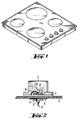
- the hob has as its base body a glass ceramic plate 4 surrounded by a separate frame with a single or a plurality of hotplates located at a distance from one another.
- the heaters for example radiant heaters, for the hotplates are arranged on the back or underside of the plate and emit their radiant heat through the plate on the front or top thereof, onto which cooking vessels can be placed.
- the actuators 1 are here between the cooktops and an outer edge of the plate immediately adjacent and approximately in a row parallel to this outer edge.
- the actuators 1 are spaced apart and can rest on the top of the plate with its lower end faces.
- the respective actuating element 1 is the plastic gag 1 usually used in such devices, which has a handle on the outside of a circular disc for gripping with the fingers of one hand and with the inside 3 of the circular disc parallel to the plate 4 and abuts the top.
- the handle bar and the circular disc are made in one piece.
- a e.g. ring-shaped perforated, magnetizable disc 2 made of ferromagnetic material.
- a signal window or an opening 21 in the center of this disc 2 a signal conductor 8 or fiber optic cable is let into the gag 1, which can essentially be firmly embedded in the material of the gag 1.
- Both ends of the glass fiber strand 8, which has constant cross-sections, are flush with the front bearing side 3 or end face of the knob 1, one end 81 of the signal bridge 8 thus formed being arranged centrally or in the axis of the knob 1.
- the signal conductor 8 is curved approximately semicircularly, so that the two end faces of the bridge 8 can lie in a common plane, but both are covered by the material of the toggle 1 on the outer circumference. In the area in which the signal conductor 8 passes through the annular disk-shaped member 2, it need not be embedded in the material of the lever 1.
- the link 2 which is slightly set back in relation to the end face 3, is, however, completely embedded firmly in the material of the toggle 1 and covered on all sides by this material.
- this material forms a thin covering of the associated end face of the link 2, this covering also covering and closing the opening 81, but being penetrated by the associated end 81 of the signal conductor 8.
- the end face 3 can be formed evenly over its entire extent and the wafer-thin cover or, to reduce the friction with respect to the plate 4, can be formed only by individual knobs or webs.
- a disc-like or ring-shaped magnet 7, possibly directly on the plate 4, is firmly attached underneath the plate 4 or on its inside facing away from the toggle 1. Radially adjacent to or around the magnet 7 are in a ring around the axis of rotation of the knob 1 photoelectric elements 5, which can also be attached directly to the plate 4. Underneath is a light source 6, which can be secured directly on the plate 4, shines through the central opening 71 of the link 7 and against which the elements 5 can be shielded.
- the two links 2, 7 can have the same inside and / or outside width or thickness and consist of the same material and lie coaxially with one another.
- One end face of the signal conductor 8 forms the signal input and the other end face forms the signal output.
- the end surface lying in the axis of rotation is expediently provided as a signal input, so that the light source 6 is also arranged in the same axis and can radiate equally against the signal input in any rotational position of the knob 1.
- the signal namely light
- the signal is sent by the light source 6 through the opening 71, then through the plate 4 and finally into the signal input, from which it passes along the bridge 8 to the signal output and is directed there opposite to the signal input, but also parallel to the axis of rotation is.
- the light comes back through the plate 4 against the sensor ring 5, the radial distance from the axis of rotation of which can be the same as that between the signal input and the signal output.
- the light strikes another of the photoelectric elements 5.
- the signal transmitted in this way is then fed to an evaluation circuit (not shown in more detail) and is implemented by the latter to control the associated setting unit.
- the plate 4 In the area covered by the toggle 1 or the control arrangement 5, 6, 7, 71, the plate 4 is free of openings, since no transmission element or switch shaft is required for signal transmission.
- Field forces such as magnetic forces, are expediently provided to secure the toggle 1 in position relative to the plate 4. These forces can secure the toggle 1 axially against lifting and / or radially against lateral displacement, but mechanically interlocking or sliding elements can advantageously be provided for the radial securing or centering.
- the magnet 7 lying under the plate 4 exerts so much force that the toggle 1 located above is fixed in its axial or radial position due to its holding member 2 which is completely enclosed or embedded in it, and nevertheless with respect to parts 4, 5, 6 is rotatably mounted.
- the gag 1 can nevertheless be lifted manually and without tools by applying a correspondingly high force from its operating position axially from the switch panel or the plate 4 or from its position centered relative to the ring arrangement 5, 7 radially along the plate 4 from the force field of the magnet 7 slidable.
- the toggle 1 By simply removing the toggle 1 from the operating position, it can be secured against unauthorized operation by children or the like. If all the knobs 1 are removed from the glass ceramic surface, the plate 4 forms a worktop which is expanded or enlarged by the operating field of the knobs 1 within a larger overall plate which receives the plate 4, without the enlarged working surface being obstructed by the knobs 1. The cleaning of the glass ceramic surface is also considerably simplified by removing the gag 1.
- the actuator 1 can be positively secured, for example, that a centering member is firmly attached to the top of the plate 4 by adhesion or gluing.
- This securing or centering element for example a cone made of plastic, can lie in the axis of rotation and can therefore be completely covered by the actuating element 1.
- the centering member expediently engages in a complementary opening of the actuating member 1 which passes through the end face 3 and can be delimited by the member 2.
- the securing element in the center is expediently provided with an opening for the beam path between light source 6 and signal input 81.
- the securing element can be arranged in such a way that it keeps the end face 3 at a small gap distance from the plate 4 and thus the actuating element 1 in contact with the plate 4.
- the securing element can also be provided for axially securing the actuating element 1 against lifting, for example via a resilient snap connection which allows the actuating element 1 to rotate freely, but only disengages when the actuating element 1 is lifted when a correspondingly high lifting force is applied.
- This axial securing can be provided instead of or in addition to the magnetic securing, wherein the holding member 7 can also be arranged on the securing member and can then be at a distance from the member 2 that is smaller than the thickness of the plate 4.
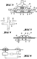
- a glass ceramic plate 31 is shown in cross section in FIG. 3. This plate runs, for example, horizontally in a cooker and is used to put the cooking vessels on.
- a magnet 33 is attached to the underside 32 of the plate with a holder (not shown in detail). The magnet 33 abuts the bottom 32. Its magnetic axis, i. H. the connecting line between its north pole and its south pole runs perpendicular to the underside 32 of the plate 31 made of glass ceramic.
- a sheet metal part 34 is attached to the magnet 33, which has a plurality of arms 35 which extend outward in a star shape. The arms 35 are approximated in their end regions of the plate 31 and form a plurality of magnetic poles 36 there.
- a mounting plate 37 is attached between the sheet metal part 34 and the plate 31 and, like the magnet 33 and the sheet metal part 34, is held in a fixed position.
- a plurality of sensors 38 are attached to the mounting plate 37, which should only be shown schematically.
- the top 39 of the plate 1 is formed in the area of the magnet 33 in exactly the same way as in the rest of the area, and thus does not contain a depression or an opening or any other special design.
- An operating element 40 is placed on top 39, which has a disk-like part 41 with a handle attachment 42.
- the disc part 41 is delimited on its underside by a sheet metal part 43, which corresponds approximately in shape and dimension to the sheet metal part 34 on the underside of the plate 31.
- the ends 44 of arms of the sheet metal part of the plate 31 are approximated.
- an element 45 of ferromagnetic material corresponding in shape and size to the magnet 33 is attached, in particular likewise a magnet.
- the magnet is also oriented so that its magnetic axis is perpendicular to the bearing surface, which is formed by one end of the magnet 45.
- the orientation of the magnet 45 is chosen in exactly the same way as the orientation of the magnet 33 on the underside of the plate 31, so that the north pole of the lower magnet 33 attracts the south pole of the upper magnet 45. This attraction centers the upper magnet 45 and thus the entire control element 40 with respect to the lower magnet 33.
- the operating element 40 can be rotated about the magnetic axis of the lower magnet 33. The centering is retained even if an operator tries to move the handle sideways.
- the control element can only be moved away from the position of the magnet 33 when a greater lateral force is applied.
- two such sensors 38 are present, which are along the circumference about the magnetic axis are arranged offset that they do not cooperate with the ends 44 of the arms of the sheet metal part 43 at the same time.
- a magnet 33 is rotatably mounted about a fixed axis 46. Details of the pivot bearing are not shown.
- a disk 47 is connected in a rotationally fixed manner thereto, which disk is also rotated when the magnet 33 is rotated.
- two sensors 49 are arranged, one above the disk 47 and one below the disk 47. The two sensors 49 can detect a change in the rotational position of the disk 47, and possibly also the absolute position of the disk 47.
- An operating element 40 is arranged on the top of the plate 31, which is constructed similarly to the operating element 40 of the embodiment according to FIG. 3, but which has a magnet 45 below the sheet metal part 43, the magnetic axis of which is oriented parallel to the surface of the plate 31 .
- the magnetic axis of the magnet 33 arranged below the plate 31 is also arranged parallel to the plate 31.
- the upper magnet 45 is positioned antiparallel to the magnet 33 on the underside and remains in this position. If the control element 40 is rotated about the axis 46, the magnet 33 and thus the disk 47 also rotate.
- the sensors 49 can therefore indirectly determine the change in the rotational position of the operating element 40 by determining the rotational position of the disk 47.
- Fig. 6 shows a separate switch-on device that can be activated with the control element.
- the electronics are powered by the mains voltage.
- a switch which can be controlled via a self-holding relay 50 is contained in the feed line.
- a reed contact is connected in parallel to this switch.
- the self-holding relay opens after a short time. Then a movement of the control element (s) at the positions assigned to them cannot serve to switch the power supply on again. If the device is to be switched on again, it is necessary to slide an operating element over the reed contact so that it is closed and the electronics supplied with voltage. This then leads to the activation of the self-holding relay, so that a rotation of the operating elements at the assigned points now leads to the device being switched on.
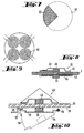
- the control element 51 in FIGS. 7 and 8 has a sector 52 made of a metallic material which is opposed to several the underside of the plate 31 arranged coils 53 is rotated. If the sector 42 is rotated via a specific coil 53, its inductance changes. In this way, the absolute position of the control element 51 can be determined. Depending on the number of coils 53, a more or less precise determination of the absolute angular position of control element 51 can be achieved.
- the coils 53 are mounted as a sensor element on a plate 54, which is held stationary.
- a magnet 33 arranged on the underside and an upper magnet 45 assigned to the operating element, the underside of which at the same time forms the support surface, are again used for centering the control element and for fixing it. Again they can Ends 44 of the arms of the sheet metal part 43 are used to effect a latching of the operating element 51 with the magnetic poles 36 arranged below the plate 31.
- sensors have been shown that act magnetically or optically. Of course, other sensors can also be used with which a change in the position of the control element can be determined.
- FIG. 10 shows an embodiment which is similar to the embodiment according to FIG. 3.
- the magnet 33 arranged on the underside 32 of the plate 31 is fastened on a mounting element 55 which is pivotally articulated laterally on a horizontal axis 56.
- the mounting element 55 can be made of metal, for example, and form part of a switch 57.
- the second contact 58 is arranged in a stationary manner. If the holding element 55 is pivoted downward, the switch 57 opens. If the operating element 40 is now pushed over the point where the magnet 33 is located, it is attracted by the upper magnet 45. This leads to the fact that the holding element 55 folds up in the direction of the arrow 59 and thus closes the switch 57. In this way, galvanic isolation can be brought about by pushing away the operating element 40.
- the distance between the contacts of the switch should have a certain minimum value of, for example, 3 mm.
- galvanic isolation can also be achieved using a reed switch.
- Fig. 11 shows schematically the arrangement of several controls in an electrical device, such as a stove.
- the is used to control a first hotplate Control arrangement 60
- a second control arrangement 61 is used for a second hotplate.
- the control arrangement 60 can be constructed like the embodiment according to FIG. 3, while the control arrangement 61 is formed by a type of variable capacitor.
- the controls are connected via measuring amplifiers 62 or pulse formers 63 to an evaluation logic 64 which controls both displays 65 and circuit breakers 66.
- a separate circuit breaker 66 is provided for each hotplate.
- the display 65 is used to display settings of the hot plates, and possibly also to display residual heat.
- the already mentioned latching which is generated magnetically, leads to the rotating control element remaining in a defined position after being released.
- the control element can be designed with a central magnet and can be provided with a sheet metal part having at least two arms. It is also possible to provide additional magnets at the ends of the arms of the sheet metal part.
- the invention proposes to produce the operating element as a molded part made of permanent magnetic material, the at least two arms of which have opposite polarity to the center.
- the magnetic field changes that occur when the control element is turned can be used to control sensors that respond to it.
- These sensors can be Hall sensors, coils, magnetoresistive sensors or reed contacts.
- the position of the control element can be determined by means of capacitive, optical, inductive or electromagnetic waves.
- the evaluation logic is designed in such a way that a minimum and / or maximum value cannot be fallen below or exceeded by turning the control element.
- control element is laterally removed from the area of action of the magnet arranged below, the control of the electrical device is switched off as a whole.
- control elements for controlling a hob or several hot plates, only the head end for which the control element is removed should be switched off.
- control elements are switched to zero, the device is completely switched off after a predetermined period of time. Then turning on a control element can no longer be switched on. Instead, it is necessary to remove at least one control element from the operating position for a certain time and then to return it to the operating position.
Landscapes
- Engineering & Computer Science (AREA)
- Chemical & Material Sciences (AREA)
- Ceramic Engineering (AREA)
- Combustion & Propulsion (AREA)
- Mechanical Engineering (AREA)
- General Engineering & Computer Science (AREA)
- Rotary Switch, Piano Key Switch, And Lever Switch (AREA)
- Electric Stoves And Ranges (AREA)
- Selective Calling Equipment (AREA)
- Preparation Of Compounds By Using Micro-Organisms (AREA)
- Massaging Devices (AREA)
- Re-Forming, After-Treatment, Cutting And Transporting Of Glass Products (AREA)
- Relay Circuits (AREA)
- Electronic Switches (AREA)
- Toys (AREA)
- Induction Heating Cooking Devices (AREA)
- Control Of Resistance Heating (AREA)
- Baking, Grill, Roasting (AREA)
Applications Claiming Priority (4)
| Application Number | Priority Date | Filing Date | Title |
|---|---|---|---|
| DE29605163U | 1996-03-20 | ||
| DE29605163U DE29605163U1 (de) | 1996-03-20 | 1996-03-20 | Schalterknebel-Anordnung zur Betriebs-Steuerung von Geräten, wie Haushaltsgeräten |
| DE19706169 | 1997-02-17 | ||
| DE19706169 | 1997-02-17 |
Publications (3)
| Publication Number | Publication Date |
|---|---|
| EP0797227A2 true EP0797227A2 (fr) | 1997-09-24 |
| EP0797227A3 EP0797227A3 (fr) | 1998-08-19 |
| EP0797227B1 EP0797227B1 (fr) | 2003-11-19 |
Family
ID=26034040
Family Applications (1)
| Application Number | Title | Priority Date | Filing Date |
|---|---|---|---|
| EP97104327A Expired - Lifetime EP0797227B1 (fr) | 1996-03-20 | 1997-03-13 | Dispositif de commande d'appareils à commande électrique |
Country Status (7)
| Country | Link |
|---|---|
| US (1) | US5920131A (fr) |
| EP (1) | EP0797227B1 (fr) |
| AT (1) | ATE254799T1 (fr) |
| DE (1) | DE59711012D1 (fr) |
| ES (1) | ES2212006T3 (fr) |
| PL (1) | PL184851B1 (fr) |
| TR (1) | TR199700218A2 (fr) |
Cited By (37)
| Publication number | Priority date | Publication date | Assignee | Title |
|---|---|---|---|---|
| EP0962707A2 (fr) | 1998-06-05 | 1999-12-08 | BSH Bosch und Siemens Hausgeräte GmbH | Unité de commande pour appareil ménager électrique |
| DE19859105A1 (de) * | 1998-12-21 | 2000-06-29 | Ego Elektro Geraetebau Gmbh | Anordnung zur Steuerung von elektrisch ansteuerbaren Geräten, insbesondere Elektrokochgeräten |
| DE19906365A1 (de) * | 1999-02-16 | 2000-08-17 | Bsh Bosch Siemens Hausgeraete | Bedienelement, beispielsweise für ein Kochfeld |
| DE10035592A1 (de) * | 2000-07-21 | 2002-01-31 | Ego Elektro Geraetebau Gmbh | Anordnung zur Steuerung von elektrisch ansteuerbaren Geräten, insbesondere Elektrowärmegeräten |
| DE10052585A1 (de) * | 2000-10-24 | 2002-05-02 | Ego Elektro Geraetebau Gmbh | Betätigungseinrichtung für ein Kochfeld |
| DE10063693C1 (de) * | 2000-12-20 | 2002-08-01 | Bsh Bosch Siemens Hausgeraete | Drehknebeleinrichtung |
| DE10126076A1 (de) * | 2001-05-29 | 2002-12-19 | Rohde & Schwarz | Impulsgeber |
| DE10202493A1 (de) * | 2002-01-23 | 2003-07-31 | Bsh Bosch Siemens Hausgeraete | Bedieneinrichtung für ein Haushaltsgerät |
| DE10229629A1 (de) * | 2002-07-02 | 2004-01-29 | BSH Bosch und Siemens Hausgeräte GmbH | Vorrichtung zur Steuerung von elektrisch ansteuerbaren Geräten, insbesondere von elektrischen Haushaltsgeräten |
| DE10330912A1 (de) * | 2003-07-07 | 2005-02-03 | E.G.O. Elektro-Gerätebau GmbH | Sensorvorrichtung zur Erkennung einer Auslösebewegung |
| WO2005038350A1 (fr) * | 2003-10-15 | 2005-04-28 | E.G.O. Elektro-Gerätebau GmbH | Dispositif de commande |
| DE10212953B4 (de) * | 2002-03-19 | 2005-05-04 | E.G.O. Elektro-Gerätebau GmbH | Bedienvorrichtung für ein Elektrogerät |
| DE102004013947B3 (de) * | 2004-03-22 | 2005-12-22 | Diehl Ako Stiftung & Co. Kg | Bedienvorrichtung für ein Glaskeramikkochfeld |
| DE102005018275A1 (de) * | 2005-04-14 | 2006-10-19 | E.G.O. Elektro-Gerätebau GmbH | Bedienvorrichtung |
| DE102005049995A1 (de) * | 2005-10-12 | 2007-04-19 | E.G.O. Elektro-Gerätebau GmbH | Bedienvorrichtung für ein Elektrogerät und Bedienverfahren zur Bedienung eines Elektrogerätes |
| WO2009010252A2 (fr) | 2007-07-18 | 2009-01-22 | E.G.O. Elektro-Gerätebau GmbH | Dispositif de commande pour un appareil électrique tel qu'une plaque de cuisson ou analogue, et dispositif correspondant |
| WO2009109623A2 (fr) | 2008-03-07 | 2009-09-11 | BSH Bosch und Siemens Hausgeräte GmbH | Dispositif de commande pour appareil électroménager comprenant une manette de commande et procédé d'utilisation d'un système de commande |
| DE19959224B4 (de) * | 1999-12-08 | 2010-07-01 | E.G.O. Elektro-Gerätebau GmbH | System bestehend aus einem Elektrokochgerät und einer davon gesonderten Bedieneinheit |
| WO2011039064A1 (fr) * | 2009-09-29 | 2011-04-07 | BSH Bosch und Siemens Hausgeräte GmbH | Appareil électroménager |
| DE102011002410A1 (de) * | 2011-01-03 | 2012-07-05 | E.G.O. Elektro-Gerätebau GmbH | Bedieneinrichtung für ein Elektrogerät |
| US8330713B2 (en) | 2008-07-25 | 2012-12-11 | Visteon Global Technologies, Inc. | Touch-sensitive display device with an integrated mechanical operating part for motor vehicles |
| DE102012001997A1 (de) | 2012-02-03 | 2013-08-08 | Micronas Gmbh | Bedienvorrichtung für ein Elektrogerät |
| WO2014048812A1 (fr) * | 2012-09-26 | 2014-04-03 | BSH Bosch und Siemens Hausgeräte GmbH | Dispositif d'entrée pour un appareil électrique |
| EP2860459A1 (fr) * | 2013-09-03 | 2015-04-15 | BSH Hausgeräte GmbH | Dispositif de commande pour un appareil ménager |
| EP2389542B1 (fr) * | 2009-01-23 | 2016-06-15 | BSH Hausgeräte GmbH | Dispositif de commande d'un appareil électroménager |
| AT15372U1 (de) * | 2015-03-13 | 2017-07-15 | Engel Austria Gmbh | Anordnung aus einer Bedieneinheit und einem Bedienelement |
| DE102016206477A1 (de) | 2016-04-18 | 2017-10-19 | E.G.O. Elektro-Gerätebau GmbH | Bedieneinrichtung für ein Elektrogerät und Elektrogerät |
| CN107788861A (zh) * | 2016-09-01 | 2018-03-13 | 三星电子株式会社 | 烹饪装置及其控制方法 |
| DE102013208640B4 (de) | 2013-05-10 | 2019-03-28 | GSI Glastechnologie GmbH | Bedienvorrichtung mit einer Basisplatte aus einem nichtmagnetischen Material und einem berührungsempfindlichen Sensor |
| US10302306B2 (en) | 2017-04-14 | 2019-05-28 | Haier Us Appliance Solutions, Inc. | Cooking appliance and knob assembly |
| US10447262B2 (en) | 2017-04-14 | 2019-10-15 | Haier Us Appliance Solutions, Inc. | Cooking appliance and knob assembly removably mounted to a control panel of the cooking appliance |
| DE102019208064B3 (de) * | 2019-06-03 | 2020-08-13 | E.G.O. Elektro-Gerätebau GmbH | Bedieneinrichtung für ein Elektrogerät und Verfahren zur Bedienung eines Elektrogeräts |
| DE102019203807A1 (de) * | 2019-03-20 | 2020-09-24 | E.G.O. Elektro-Gerätebau GmbH | Bedieneinrichtung für ein Elektrogerät und Elektrogerät mit einer solchen Bedieneinrichtung |
| EP3763998A1 (fr) * | 2019-07-12 | 2021-01-13 | Electrolux Appliances Aktiebolag | Élément de commande pour une interface utilisateur d'un appareil ménager |
| DE102004020825B4 (de) | 2004-04-28 | 2021-08-12 | BSH Hausgeräte GmbH | Bedienelement |
| DE102023129696A1 (de) | 2023-10-27 | 2025-04-30 | E.G.O. Elektro-Gerätebau GmbH | Bedieneinrichtung für ein Elektrogerät und Elektrogerät |
| EP4596974A1 (fr) | 2024-01-30 | 2025-08-06 | E.G.O. Elektro-Gerätebau GmbH | Procédé de commande d'un appareil électrique et appareil électrique |
Families Citing this family (42)
| Publication number | Priority date | Publication date | Assignee | Title |
|---|---|---|---|---|
| DE69831226T2 (de) * | 1997-11-20 | 2006-03-30 | Seiko Epson Corp. | Elektronische vorrichtung |
| EP1261895B1 (fr) * | 1999-12-10 | 2005-11-23 | Sensopad Limited | Interface homme-machine |
| GB2366080A (en) * | 2000-08-09 | 2002-02-27 | Herga Electric | Switch assembly |
| US7075195B2 (en) | 2002-01-14 | 2006-07-11 | Safestart System, Llc | Electrical safety lockout mechanism for power tools and other hazardous machinery |
| DE10212929A1 (de) * | 2002-03-19 | 2003-10-02 | Ego Elektro Geraetebau Gmbh | Bedienvorrichtung für ein Elektrogerät |
| DE10212954A1 (de) * | 2002-03-19 | 2003-10-02 | Ego Elektro Geraetebau Gmbh | Bedienvorrichtung für ein Elektrogerät |
| DE50312450D1 (de) * | 2002-08-14 | 2010-04-08 | Bsh Bosch Siemens Hausgeraete | Bedieneinheit für ein elektrisches haushaltsgerät |
| CN1708672B (zh) * | 2002-10-31 | 2010-05-12 | 量研科技股份有限公司 | 电荷转移电容位置传感器 |
| GB2418493B (en) | 2003-08-21 | 2006-11-15 | Harald Philipp | Capacitive position sensor |
| DE10342335B4 (de) * | 2003-09-11 | 2007-02-01 | Preh Gmbh | Bedienelement |
| US20060001512A1 (en) * | 2004-07-01 | 2006-01-05 | Garcia Jorge L | Rotary control for a communication device |
| DE202005019978U1 (de) * | 2005-10-12 | 2006-04-20 | E.G.O. Elektro-Gerätebau GmbH | Bedienvorrichtung für ein Elektrogerät |
| JP4404057B2 (ja) * | 2006-02-10 | 2010-01-27 | ソニー株式会社 | 無接点スイッチとそれを用いた記録メディアおよび操作部材 |
| DE102006045735A1 (de) * | 2006-09-18 | 2008-03-27 | E.G.O. Elektro-Gerätebau GmbH | Bedienvorrichtung für ein Elektrogerät und Bedienverfahren |
| US7889187B2 (en) * | 2007-04-20 | 2011-02-15 | Kohler Co. | User interface for controlling a bathroom plumbing fixture |
| US8570028B2 (en) | 2007-05-10 | 2013-10-29 | Cambridge Integrated Circuits Limited | Transducer for a position sensor |
| US7936242B2 (en) * | 2007-09-14 | 2011-05-03 | William N Carpenter | Magnetically operated electrical switch |
| DE102007057410B3 (de) * | 2007-11-27 | 2009-07-30 | Uhde Gmbh | Mechanismus und Verfahren zur automatisierbaren Verriegelung von Türen, Türkörpern oder Türrahmen horizontaler Koksofenkammern |
| JP5143090B2 (ja) * | 2008-06-10 | 2013-02-13 | 三菱電機株式会社 | 誘導加熱調理器 |
| DE102009008192A1 (de) * | 2009-02-03 | 2010-08-05 | E.G.O. Elektro-Gerätebau GmbH | Bedieneinrichtung für ein Elektrogerät und Bedienverfahren |
| CA2757490A1 (fr) * | 2009-04-03 | 2010-10-07 | Touchsensor Technologies, Llc | Interface de bouton virtuel et procede |
| DE102009048494A1 (de) * | 2009-09-25 | 2011-04-07 | E.G.O. Elektro-Gerätebau GmbH | Verfahren und Vorrichtung zur Bedienung eines Elektrogerätes |
| US8881769B2 (en) * | 2010-09-20 | 2014-11-11 | Bsh Bosch Und Siemens Hausgeraete Gmbh | Structure of a gas-valve unit |
| DE102010051491A1 (de) * | 2010-11-15 | 2012-05-16 | Atlas Elektronik Gmbh | Unterwasserfahrzeug und Unterwassersystem mit einem Unterwasserfahrzeug |
| US8662071B2 (en) | 2011-02-14 | 2014-03-04 | Bsh Home Appliances Corporation | Household gas appliance with a magnetically controlled gas supply system |
| US9565970B2 (en) * | 2011-04-14 | 2017-02-14 | Electrodomesticos Taurus Sl | Cooking system including a cooking hob and a cooking vessel |
| US20140015596A1 (en) * | 2012-04-20 | 2014-01-16 | Bryan A. Martin | Magnetic field switches |
| DE102012014535A1 (de) | 2012-07-21 | 2014-01-23 | Diehl Ako Stiftung & Co. Kg | Drehknebel-Bedienvorrichtung |
| CN102997292B (zh) * | 2012-11-30 | 2015-11-18 | 九阳股份有限公司 | 一种方便清洁的旋控式电磁炉 |
| DE102014216389A1 (de) * | 2014-08-19 | 2016-02-25 | BSH Hausgeräte GmbH | Bedienvorrichtung für ein Haushaltsgerät mit stabil positioniertem ringförmigen Bedienelement-Vorderteil und Haushaltsgerät mit einer derartigen Bedienvorrichtung |
| US9552951B2 (en) * | 2015-03-06 | 2017-01-24 | Cooper Technologies Company | High voltage compact fusible disconnect switch device with magnetic arc deflection assembly |
| CN105138068B (zh) * | 2015-08-31 | 2017-03-01 | 广东美的厨房电器制造有限公司 | 旋钮结构、旋转角度确定方法、装置和家用电器 |
| US10854414B2 (en) | 2016-05-11 | 2020-12-01 | Eaton Intelligent Power Limited | High voltage electrical disconnect device with magnetic arc deflection assembly |
| CN206301238U (zh) * | 2016-12-13 | 2017-07-04 | 广东美的厨房电器制造有限公司 | 磁控旋钮及家用电器 |
| DE102017209129A1 (de) | 2017-05-31 | 2018-12-06 | BSH Hausgeräte GmbH | Bedienvorrichtung für ein Haushaltsgerät mit bewegbarem Haltemagnet in einem Bedienelement sowie Haushaltsgerät |
| GB201721722D0 (en) | 2017-12-22 | 2018-02-07 | Pilkington Group Ltd | Switching device |
| US10636607B2 (en) | 2017-12-27 | 2020-04-28 | Eaton Intelligent Power Limited | High voltage compact fused disconnect switch device with bi-directional magnetic arc deflection assembly |
| DE102018200337A1 (de) * | 2018-01-11 | 2019-07-11 | BSH Hausgeräte GmbH | Bedienvorrichtung für ein Haushaltsgerät |
| EP3561389B1 (fr) * | 2018-04-27 | 2021-01-27 | Electrolux Appliances Aktiebolag | Appareil ménager conçu pour un mode veille |
| EP3562265B1 (fr) * | 2018-04-27 | 2022-04-13 | Electrolux Appliances Aktiebolag | Appareil ménager conçu pour un mode veille |
| EP4018781A4 (fr) * | 2019-08-21 | 2023-04-12 | Ghsp, Inc. | Table de cuisson à induction avec écran intégré |
| WO2023279253A1 (fr) * | 2021-07-06 | 2023-01-12 | 深圳拓邦股份有限公司 | Bouton, procédé de commande, dispositif de commande et appareil électrique |
Family Cites Families (20)
| Publication number | Priority date | Publication date | Assignee | Title |
|---|---|---|---|---|
| DE1122796B (de) * | 1957-10-31 | 1962-01-25 | Licentia Gmbh | Drehknopf |
| US3711672A (en) * | 1972-01-11 | 1973-01-16 | Westinghouse Electric Corp | Magnetically coupled control for appliance |
| US3852558A (en) * | 1974-03-27 | 1974-12-03 | Westinghouse Electric Corp | Magnetically coupled control for cooking platform |
| US4233593A (en) * | 1978-06-12 | 1980-11-11 | General Electric Company | Capacitive touch control and display |
| GB2034043A (en) * | 1978-10-09 | 1980-05-29 | Turnright Controls | Improvements in or Relating to Controls for Electrical Circuits |
| JPS5693286A (en) * | 1979-12-27 | 1981-07-28 | Tokyo Shibaura Electric Co | Induction heating cooking device |
| DE3442583A1 (de) * | 1984-11-22 | 1986-05-28 | Christoph 6240 Königstein Vohrer | Flexibler schlauch zum leiten eines stroemungsmittels, mit mindestens einer in einer schlauchwandung integrierten steuerleitung |
| DE3543783A1 (de) * | 1985-12-09 | 1987-06-11 | Siemens Ag | Anordnung zur steuerung eines cursors |
| JPS6343553U (fr) * | 1986-09-09 | 1988-03-23 | ||
| GB8725737D0 (en) * | 1987-11-03 | 1987-12-09 | Electrolux Ab | Control apparatus |
| DE3834821A1 (de) * | 1988-10-13 | 1990-05-03 | Thomson Brandt Gmbh | Optische uebertragungseinrichtung fuer digitale signale |
| US4997828A (en) * | 1989-02-14 | 1991-03-05 | The Rockefeller University | Method of weight control by low level administration of cobalt protoporphyrin or cobalt mesoporphyrin |
| DE3908786A1 (de) * | 1989-03-17 | 1989-08-03 | Cordell Steve | Verfahren zur informationsuebertragung zwischen platinen einer elektronischen schaltung |
| FR2648580B1 (fr) * | 1989-06-16 | 1991-09-20 | Rexroth Sigma | Procede pour etalonner un dispositif de telecommande electrique du type manipulateur ou analogue, et dispositif agence pour mettre en oeuvre ce procede |
| FR2648582B1 (fr) * | 1989-06-16 | 1996-08-09 | Rexroth Sigma | Dispositif de telecommande electrique du type manipulateur ou analogue |
| DE8910606U1 (de) * | 1989-09-06 | 1989-10-26 | J.D. Möller Optische Werke GmbH, 22880 Wedel | Drehknopf-Vorrichtung zum Auswählen bestimmter Funktionsarten eines Gerätes, insbesondere eines elektronischen Phoropters |
| DE59206720D1 (de) * | 1991-01-28 | 1996-08-14 | Electrolux Ag | Verfahren zur Ansteuerung des Betriebes eines Kochgerätes und Kochgerätssteuerung |
| FR2699002B1 (fr) * | 1992-12-04 | 1995-03-24 | Scholtes Ets Eugen | Commutateur de commande de la mise sous tension électrique, notamment d'éléments chauffants pour appareil de cuisson domestique. |
| DE4336729C2 (de) * | 1993-10-28 | 2003-04-24 | Marquardt Gmbh | Optischer Schalter |
| DE4432399C2 (de) * | 1994-09-12 | 1998-08-20 | Miele & Cie | Magnetempfindlicher Schalter |
-
1997
- 1997-03-13 DE DE59711012T patent/DE59711012D1/de not_active Expired - Lifetime
- 1997-03-13 AT AT97104327T patent/ATE254799T1/de not_active IP Right Cessation
- 1997-03-13 ES ES97104327T patent/ES2212006T3/es not_active Expired - Lifetime
- 1997-03-13 EP EP97104327A patent/EP0797227B1/fr not_active Expired - Lifetime
- 1997-03-14 US US08/818,822 patent/US5920131A/en not_active Expired - Lifetime
- 1997-03-18 PL PL97319025A patent/PL184851B1/pl unknown
- 1997-03-20 TR TR97/00218A patent/TR199700218A2/xx unknown
Cited By (56)
| Publication number | Priority date | Publication date | Assignee | Title |
|---|---|---|---|---|
| EP0962707A2 (fr) | 1998-06-05 | 1999-12-08 | BSH Bosch und Siemens Hausgeräte GmbH | Unité de commande pour appareil ménager électrique |
| DE19859105A1 (de) * | 1998-12-21 | 2000-06-29 | Ego Elektro Geraetebau Gmbh | Anordnung zur Steuerung von elektrisch ansteuerbaren Geräten, insbesondere Elektrokochgeräten |
| EP1014001A3 (fr) * | 1998-12-21 | 2001-10-04 | E.G.O. ELEKTRO-GERÄTEBAU GmbH | Dispositif de commande d'appareils à commande électrique, notamment appareils de cuisson électriques |
| US6498326B1 (en) | 1998-12-21 | 2002-12-24 | E.G.O. Elektro-Geratebau Gmbh | Arrangement for the control of electrically controllable appliances, particularly electric cookers |
| DE19906365B4 (de) * | 1999-02-16 | 2009-02-26 | BSH Bosch und Siemens Hausgeräte GmbH | Kochfeld mit Bedienelement |
| DE19906365A1 (de) * | 1999-02-16 | 2000-08-17 | Bsh Bosch Siemens Hausgeraete | Bedienelement, beispielsweise für ein Kochfeld |
| DE19959224B4 (de) * | 1999-12-08 | 2010-07-01 | E.G.O. Elektro-Gerätebau GmbH | System bestehend aus einem Elektrokochgerät und einer davon gesonderten Bedieneinheit |
| DE10035592A1 (de) * | 2000-07-21 | 2002-01-31 | Ego Elektro Geraetebau Gmbh | Anordnung zur Steuerung von elektrisch ansteuerbaren Geräten, insbesondere Elektrowärmegeräten |
| DE10052585A1 (de) * | 2000-10-24 | 2002-05-02 | Ego Elektro Geraetebau Gmbh | Betätigungseinrichtung für ein Kochfeld |
| DE10052585C2 (de) * | 2000-10-24 | 2003-11-13 | Ego Elektro Geraetebau Gmbh | Betätigungseinrichtung für ein Kochfeld |
| DE10063693C1 (de) * | 2000-12-20 | 2002-08-01 | Bsh Bosch Siemens Hausgeraete | Drehknebeleinrichtung |
| DE10126076A1 (de) * | 2001-05-29 | 2002-12-19 | Rohde & Schwarz | Impulsgeber |
| DE10126076B4 (de) * | 2001-05-29 | 2006-05-24 | Rohde & Schwarz Gmbh & Co. Kg | Impulsgeber |
| DE10202493A1 (de) * | 2002-01-23 | 2003-07-31 | Bsh Bosch Siemens Hausgeraete | Bedieneinrichtung für ein Haushaltsgerät |
| DE10212953B4 (de) * | 2002-03-19 | 2005-05-04 | E.G.O. Elektro-Gerätebau GmbH | Bedienvorrichtung für ein Elektrogerät |
| DE10229629A1 (de) * | 2002-07-02 | 2004-01-29 | BSH Bosch und Siemens Hausgeräte GmbH | Vorrichtung zur Steuerung von elektrisch ansteuerbaren Geräten, insbesondere von elektrischen Haushaltsgeräten |
| DE10330912A1 (de) * | 2003-07-07 | 2005-02-03 | E.G.O. Elektro-Gerätebau GmbH | Sensorvorrichtung zur Erkennung einer Auslösebewegung |
| WO2005038350A1 (fr) * | 2003-10-15 | 2005-04-28 | E.G.O. Elektro-Gerätebau GmbH | Dispositif de commande |
| DE102004013947B3 (de) * | 2004-03-22 | 2005-12-22 | Diehl Ako Stiftung & Co. Kg | Bedienvorrichtung für ein Glaskeramikkochfeld |
| DE102004020825B4 (de) | 2004-04-28 | 2021-08-12 | BSH Hausgeräte GmbH | Bedienelement |
| DE102005018275A1 (de) * | 2005-04-14 | 2006-10-19 | E.G.O. Elektro-Gerätebau GmbH | Bedienvorrichtung |
| WO2006108619A1 (fr) * | 2005-04-14 | 2006-10-19 | E.G.O. Elektro-Gerätebau GmbH | Dispositif de commande pour appareil electrique |
| DE102005049995A1 (de) * | 2005-10-12 | 2007-04-19 | E.G.O. Elektro-Gerätebau GmbH | Bedienvorrichtung für ein Elektrogerät und Bedienverfahren zur Bedienung eines Elektrogerätes |
| WO2009010252A2 (fr) | 2007-07-18 | 2009-01-22 | E.G.O. Elektro-Gerätebau GmbH | Dispositif de commande pour un appareil électrique tel qu'une plaque de cuisson ou analogue, et dispositif correspondant |
| US8232507B2 (en) | 2007-07-18 | 2012-07-31 | E.G.O. Elektro-Geraetebau Gmbh | Operating device for an electric appliance such as a hob and arrangement thereof |
| WO2009010252A3 (fr) * | 2007-07-18 | 2009-03-19 | Ego Elektro Geraetebau Gmbh | Dispositif de commande pour un appareil électrique tel qu'une plaque de cuisson ou analogue, et dispositif correspondant |
| WO2009109623A3 (fr) * | 2008-03-07 | 2010-06-10 | BSH Bosch und Siemens Hausgeräte GmbH | Dispositif de commande pour appareil électroménager comprenant une manette de commande et procédé d'utilisation d'un système de commande |
| WO2009109623A2 (fr) | 2008-03-07 | 2009-09-11 | BSH Bosch und Siemens Hausgeräte GmbH | Dispositif de commande pour appareil électroménager comprenant une manette de commande et procédé d'utilisation d'un système de commande |
| US8330713B2 (en) | 2008-07-25 | 2012-12-11 | Visteon Global Technologies, Inc. | Touch-sensitive display device with an integrated mechanical operating part for motor vehicles |
| EP2389542B1 (fr) * | 2009-01-23 | 2016-06-15 | BSH Hausgeräte GmbH | Dispositif de commande d'un appareil électroménager |
| WO2011039064A1 (fr) * | 2009-09-29 | 2011-04-07 | BSH Bosch und Siemens Hausgeräte GmbH | Appareil électroménager |
| DE102011002410A1 (de) * | 2011-01-03 | 2012-07-05 | E.G.O. Elektro-Gerätebau GmbH | Bedieneinrichtung für ein Elektrogerät |
| DE102011002410B4 (de) * | 2011-01-03 | 2012-08-23 | E.G.O. Elektro-Gerätebau GmbH | Bedieneinrichtung für ein Elektrogerät |
| US9093237B2 (en) | 2012-02-03 | 2015-07-28 | Micronas Gmbh | Control device for an electrical appliance |
| DE102012001997A1 (de) | 2012-02-03 | 2013-08-08 | Micronas Gmbh | Bedienvorrichtung für ein Elektrogerät |
| DE102012001997B4 (de) | 2012-02-03 | 2023-02-09 | Tdk-Micronas Gmbh | Bedienvorrichtung für ein Elektrogerät |
| CN104662801A (zh) * | 2012-09-26 | 2015-05-27 | Bsh博世和西门子家用电器有限公司 | 用于电器的输入装置 |
| WO2014048812A1 (fr) * | 2012-09-26 | 2014-04-03 | BSH Bosch und Siemens Hausgeräte GmbH | Dispositif d'entrée pour un appareil électrique |
| DE102013208640B4 (de) | 2013-05-10 | 2019-03-28 | GSI Glastechnologie GmbH | Bedienvorrichtung mit einer Basisplatte aus einem nichtmagnetischen Material und einem berührungsempfindlichen Sensor |
| EP2860459A1 (fr) * | 2013-09-03 | 2015-04-15 | BSH Hausgeräte GmbH | Dispositif de commande pour un appareil ménager |
| AT15372U1 (de) * | 2015-03-13 | 2017-07-15 | Engel Austria Gmbh | Anordnung aus einer Bedieneinheit und einem Bedienelement |
| DE102016206477A1 (de) | 2016-04-18 | 2017-10-19 | E.G.O. Elektro-Gerätebau GmbH | Bedieneinrichtung für ein Elektrogerät und Elektrogerät |
| EP3236159A1 (fr) | 2016-04-18 | 2017-10-25 | E.G.O. ELEKTRO-GERÄTEBAU GmbH | Dispositif de commande pour un un appareil électrique et appareil électrique |
| DE102016206477B4 (de) * | 2016-04-18 | 2017-11-09 | E.G.O. Elektro-Gerätebau GmbH | Bedieneinrichtung für ein Elektrogerät und Elektrogerät |
| CN107788861A (zh) * | 2016-09-01 | 2018-03-13 | 三星电子株式会社 | 烹饪装置及其控制方法 |
| US10302306B2 (en) | 2017-04-14 | 2019-05-28 | Haier Us Appliance Solutions, Inc. | Cooking appliance and knob assembly |
| US10447262B2 (en) | 2017-04-14 | 2019-10-15 | Haier Us Appliance Solutions, Inc. | Cooking appliance and knob assembly removably mounted to a control panel of the cooking appliance |
| DE102019203807B4 (de) | 2019-03-20 | 2021-08-05 | E.G.O. Elektro-Gerätebau GmbH | Bedieneinrichtung für ein Elektrogerät und Elektrogerät mit einer solchen Bedieneinrichtung |
| DE102019203807A1 (de) * | 2019-03-20 | 2020-09-24 | E.G.O. Elektro-Gerätebau GmbH | Bedieneinrichtung für ein Elektrogerät und Elektrogerät mit einer solchen Bedieneinrichtung |
| DE102019208064B3 (de) * | 2019-06-03 | 2020-08-13 | E.G.O. Elektro-Gerätebau GmbH | Bedieneinrichtung für ein Elektrogerät und Verfahren zur Bedienung eines Elektrogeräts |
| EP3748234A1 (fr) | 2019-06-03 | 2020-12-09 | E.G.O. Elektro-Gerätebau GmbH | Dispositif de commande pour un appareil électrique et procédé de fonctionnement d'un appareil électrique |
| EP3763998A1 (fr) * | 2019-07-12 | 2021-01-13 | Electrolux Appliances Aktiebolag | Élément de commande pour une interface utilisateur d'un appareil ménager |
| DE102023129696A1 (de) | 2023-10-27 | 2025-04-30 | E.G.O. Elektro-Gerätebau GmbH | Bedieneinrichtung für ein Elektrogerät und Elektrogerät |
| WO2025087611A1 (fr) | 2023-10-27 | 2025-05-01 | E.G.O. Elektro-Gerätebau GmbH | Dispositif de commande pour appareil électrique et appareil électrique |
| DE102023129696B4 (de) | 2023-10-27 | 2025-06-05 | E.G.O. Elektro-Gerätebau GmbH | Bedieneinrichtung für ein Elektrogerät und Elektrogerät |
| EP4596974A1 (fr) | 2024-01-30 | 2025-08-06 | E.G.O. Elektro-Gerätebau GmbH | Procédé de commande d'un appareil électrique et appareil électrique |
Also Published As
| Publication number | Publication date |
|---|---|
| ES2212006T3 (es) | 2004-07-16 |
| ATE254799T1 (de) | 2003-12-15 |
| EP0797227A3 (fr) | 1998-08-19 |
| US5920131A (en) | 1999-07-06 |
| PL184851B1 (pl) | 2002-12-31 |
| TR199700218A2 (xx) | 1997-10-21 |
| DE59711012D1 (de) | 2003-12-24 |
| PL319025A1 (en) | 1997-09-29 |
| EP0797227B1 (fr) | 2003-11-19 |
Similar Documents
| Publication | Publication Date | Title |
|---|---|---|
| EP0797227B1 (fr) | Dispositif de commande d'appareils à commande électrique | |
| EP1873609B1 (fr) | Unité de commande pour appareil ménager électrique | |
| EP1349281B1 (fr) | Dispositif de commande pour un appareil électrique | |
| EP1775650B1 (fr) | Dispositif de commande pour appareil électrique | |
| EP1869368B1 (fr) | Dispositif de commande pour appareil electrique | |
| DE69307480T2 (de) | Befehlsschalter für ein Haushaltskochgerät | |
| EP1045300B1 (fr) | Elément de commande pour commuter et contrôler des appareils controlâbles électriquement avec un écran | |
| DE4231379C2 (de) | Mikroskop mit einem multifunktionalen Triebknopf | |
| EP1923999A2 (fr) | Dispositif de commande pour un appareil électrique et procédé de commande | |
| DE10133135A1 (de) | Stelleinheit für Gargeräte | |
| EP2420734B1 (fr) | Dispositif de commande pour un four de cuisson | |
| EP2282126B1 (fr) | Hotte aspirante dotée d'une unité de commande | |
| DE10255676B4 (de) | Bedieneinheit für ein elektrisches Gerät | |
| EP0497191A1 (fr) | Dispositif d'actionnement d'un appareil de cuisson et procédé de commande | |
| DE10035592A1 (de) | Anordnung zur Steuerung von elektrisch ansteuerbaren Geräten, insbesondere Elektrowärmegeräten | |
| DE102005049995A1 (de) | Bedienvorrichtung für ein Elektrogerät und Bedienverfahren zur Bedienung eines Elektrogerätes | |
| DE10212953A1 (de) | Bedienvorrichtung für ein Elektrogerät | |
| DE102010039559B4 (de) | Bedienvorrichtung für ein Hausgerät mit einer Energieversorgungseinrichtung sowie Hausgerät zum Zubereiten von Lebensmitteln mit einer derartigen Bedienvorrichtung | |
| DE102004005111B4 (de) | Hausgerätebedienvorrichtung | |
| DE29605163U1 (de) | Schalterknebel-Anordnung zur Betriebs-Steuerung von Geräten, wie Haushaltsgeräten | |
| EP1470739B1 (fr) | Dispositif servant faire fonctionner un appareil lectrom nager | |
| EP3748234B1 (fr) | Dispositif de commande pour un appareil électrique et procédé de fonctionnement d'un appareil électrique | |
| DE10163194A1 (de) | Elektromechanische Stufenschaltvorrichtung mit zeitgesteuerten Zusatzfunktionen | |
| DE10229629A1 (de) | Vorrichtung zur Steuerung von elektrisch ansteuerbaren Geräten, insbesondere von elektrischen Haushaltsgeräten | |
| DE102005004337B4 (de) | Verfahren zum Bedienen einer Bedieneinrichtung eines Haushaltsgroßgerätes und Bedieneinrichtung zur Durchführung des Verfahrens |
Legal Events
| Date | Code | Title | Description |
|---|---|---|---|
| PUAI | Public reference made under article 153(3) epc to a published international application that has entered the european phase |
Free format text: ORIGINAL CODE: 0009012 |
|
| AK | Designated contracting states |
Kind code of ref document: A2 Designated state(s): AT CH DE ES FR IT LI SE |
|
| PUAL | Search report despatched |
Free format text: ORIGINAL CODE: 0009013 |
|
| AK | Designated contracting states |
Kind code of ref document: A3 Designated state(s): AT CH DE ES FR IT LI SE |
|
| 17P | Request for examination filed |
Effective date: 19981212 |
|
| 17Q | First examination report despatched |
Effective date: 20020313 |
|
| GRAH | Despatch of communication of intention to grant a patent |
Free format text: ORIGINAL CODE: EPIDOS IGRA |
|
| GRAS | Grant fee paid |
Free format text: ORIGINAL CODE: EPIDOSNIGR3 |
|
| GRAA | (expected) grant |
Free format text: ORIGINAL CODE: 0009210 |
|
| AK | Designated contracting states |
Kind code of ref document: B1 Designated state(s): AT CH DE ES FR IT LI SE |
|
| REG | Reference to a national code |
Ref country code: CH Ref legal event code: EP |
|
| REF | Corresponds to: |
Ref document number: 59711012 Country of ref document: DE Date of ref document: 20031224 Kind code of ref document: P |
|
| REG | Reference to a national code |
Ref country code: CH Ref legal event code: NV Representative=s name: SUSI PRYDE-HAENI BSC |
|
| REG | Reference to a national code |
Ref country code: SE Ref legal event code: TRGR |
|
| PG25 | Lapsed in a contracting state [announced via postgrant information from national office to epo] |
Ref country code: AT Free format text: LAPSE BECAUSE OF NON-PAYMENT OF DUE FEES Effective date: 20040313 |
|
| PG25 | Lapsed in a contracting state [announced via postgrant information from national office to epo] |
Ref country code: LI Free format text: LAPSE BECAUSE OF NON-PAYMENT OF DUE FEES Effective date: 20040331 Ref country code: CH Free format text: LAPSE BECAUSE OF NON-PAYMENT OF DUE FEES Effective date: 20040331 |
|
| REG | Reference to a national code |
Ref country code: ES Ref legal event code: FG2A Ref document number: 2212006 Country of ref document: ES Kind code of ref document: T3 |
|
| ET | Fr: translation filed | ||
| PLBE | No opposition filed within time limit |
Free format text: ORIGINAL CODE: 0009261 |
|
| STAA | Information on the status of an ep patent application or granted ep patent |
Free format text: STATUS: NO OPPOSITION FILED WITHIN TIME LIMIT |
|
| 26N | No opposition filed |
Effective date: 20040820 |
|
| REG | Reference to a national code |
Ref country code: CH Ref legal event code: PL |
|
| REG | Reference to a national code |
Ref country code: FR Ref legal event code: PLFP Year of fee payment: 20 |
|
| PGFP | Annual fee paid to national office [announced via postgrant information from national office to epo] |
Ref country code: ES Payment date: 20160322 Year of fee payment: 20 |
|
| PGFP | Annual fee paid to national office [announced via postgrant information from national office to epo] |
Ref country code: SE Payment date: 20160322 Year of fee payment: 20 Ref country code: FR Payment date: 20160322 Year of fee payment: 20 |
|
| PGFP | Annual fee paid to national office [announced via postgrant information from national office to epo] |
Ref country code: DE Payment date: 20160324 Year of fee payment: 20 |
|
| PGFP | Annual fee paid to national office [announced via postgrant information from national office to epo] |
Ref country code: IT Payment date: 20160318 Year of fee payment: 20 |
|
| REG | Reference to a national code |
Ref country code: DE Ref legal event code: R071 Ref document number: 59711012 Country of ref document: DE |
|
| REG | Reference to a national code |
Ref country code: SE Ref legal event code: EUG |
|
| REG | Reference to a national code |
Ref country code: ES Ref legal event code: FD2A Effective date: 20170626 |
|
| PG25 | Lapsed in a contracting state [announced via postgrant information from national office to epo] |
Ref country code: ES Free format text: LAPSE BECAUSE OF EXPIRATION OF PROTECTION Effective date: 20170314 |