EP0797272B1 - Verfahren und Einrichtung zum Festhalten eines Kabelbundels einer Telefon- oder Datenkontaktleiste - Google Patents
Verfahren und Einrichtung zum Festhalten eines Kabelbundels einer Telefon- oder Datenkontaktleiste Download PDFInfo
- Publication number
- EP0797272B1 EP0797272B1 EP97420045A EP97420045A EP0797272B1 EP 0797272 B1 EP0797272 B1 EP 0797272B1 EP 97420045 A EP97420045 A EP 97420045A EP 97420045 A EP97420045 A EP 97420045A EP 0797272 B1 EP0797272 B1 EP 0797272B1
- Authority
- EP
- European Patent Office
- Prior art keywords
- connection
- terminal strip
- plug
- hook
- contacts
- Prior art date
- Legal status (The legal status is an assumption and is not a legal conclusion. Google has not performed a legal analysis and makes no representation as to the accuracy of the status listed.)
- Expired - Lifetime
Links
- 238000000034 method Methods 0.000 title claims abstract description 8
- 239000013013 elastic material Substances 0.000 abstract description 2
- 238000006073 displacement reaction Methods 0.000 description 8
- 238000009413 insulation Methods 0.000 description 8
- 239000004020 conductor Substances 0.000 description 2
- 239000000463 material Substances 0.000 description 2
- 239000002184 metal Substances 0.000 description 2
- 208000031968 Cadaver Diseases 0.000 description 1
- 229920001971 elastomer Polymers 0.000 description 1
- 239000000806 elastomer Substances 0.000 description 1
- 238000009434 installation Methods 0.000 description 1
- 230000004048 modification Effects 0.000 description 1
- 238000012986 modification Methods 0.000 description 1
- 210000002105 tongue Anatomy 0.000 description 1
Images

Classifications
-
- H—ELECTRICITY
- H01—ELECTRIC ELEMENTS
- H01R—ELECTRICALLY-CONDUCTIVE CONNECTIONS; STRUCTURAL ASSOCIATIONS OF A PLURALITY OF MUTUALLY-INSULATED ELECTRICAL CONNECTING ELEMENTS; COUPLING DEVICES; CURRENT COLLECTORS
- H01R13/00—Details of coupling devices of the kinds covered by groups H01R12/70 or H01R24/00 - H01R33/00
- H01R13/62—Means for facilitating engagement or disengagement of coupling parts or for holding them in engagement
- H01R13/627—Snap or like fastening
- H01R13/6275—Latching arms not integral with the housing
Definitions
- the present invention relates to a method and a device for secure connection of a patch cord to an interconnecting strip of telephone or computer lines.
- EP-A-0.524.115 of the Company Applicant describes, among other things, how one achieves, by a plug of connection appropriate, the connection of such a cord on a strip. These cords of brewing are also necessary when working with high flow rate, either to connect one or more lines to an electrical appliance, or to connect lines between them.
- a telephone or computer installation may have a very large number of strips on the same frame, these strips being very closer to each other. We are then in the presence of a real forest of patch cords that are tight against each other. If each cord of brewing is simply plugged on its ruler, it can happen that by handling it, the operator accidentally disconnects one or more other patch cords neighbors, and then do not know where to reconnect them. It can also happen that disconnects only partially one or several neighboring cords, and that it does not then not see, so that one or more lines remain disconnected without anyone knowing it.
- Document FR-A-2,698,511 describes in this connection a card of connection of a brewing cord, called "push-pull", which is provided on the one hand of a locking piece which surrounds this plug and which includes several elastic arms with hooks that come to fill in interstices of the ruler, and secondly of a mobile unlocking part axially with respect to said locking piece, which surrounds the latter and which cooperates with it to undo the snapping of the elastic arms with hooks on the ruler when axially pulling on this unlocking part.
- This known secure connection device does not require any modification of the slide.
- unlocking it which requires grasping between two fingers the unlocking piece, to pull it backwards, becomes practically impossible, without using a specially adapted tool, when one is in the presence of a forest of patch cords tight against each other because the place is not enough to pass the fingers.
- such a device is of rather complex realization and so expensive.
- the invention aims to remedy these drawbacks. It relates to this effect a method and apparatus for securely making the connection of a patch cord with a connector plug on an interconnect strip of telephone or computer lines, the connection plug being equipped with an arm, sloping and tilting, locking one of whose free end carries a hook that comes, by rocking elastic return effect, lock said connection plug on the ruler and whose other free end comes, by forced tilting effect of this locking arm, unlocking said connection plug of the strip, and the strip interconnection of telephone or computer lines comprising; two big faces and a row of insulation displacement connection contacts.
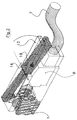
- the reference numeral 1 denotes a portion of the plastic body of a strip of interconnection of telephone lines or for example a ruler as described in the document EP-A-0.524.115 cited above. More precisely, it is here represented a front portion of the ruler that includes the connection of a single pair, that is to say, a first pair of contacts 2, 3 on the large upper face 4 of the strip and another pair of contacts 5, 6 on the large lower face of the strip, these two pairs being for example interconnected, by an elastic connection, inside the strip.
- a patch cord 7 to connect the line contacts 2, 3, 5, 6 to another strip, to an electronic device.
- This patch cord is equipped accordingly with a end plug, or connector, which is plugged on the portion or portions of the strip 1 considered.
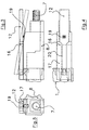
- the arm 12 tilts around a metal axis 16 which is positioned transversely in the upper part 17 of the plastic body of the form of connection 8, about mid-length of the arm 12.
- a groove 20 is provided in this upper part 17 of the plastic body of the plug to let free passage on the arm 12.
- a pin, or protuberance, 19, of such elastic material elastomer is provided in the body of the plug 8, behind the axis of 16.
- the pin 19 crushes and elastically pushes the arm 12 as to make it shuffle forward.
- a slight deformation elastic (not visible in the drawing) of this arm also creates a repulsive effect elastically forward when pressing its rear portion 18 against the resistance due to the stop 19.
- the strip 1 is designed to receive several cords 7, each provided with a connector 8, so that in reality the face 4 has several cavities 9, preferably a cavity 9 per pair 2, 3. heard also, all or part of these cavities 9 could be provided on the other large face of the slide, to the counterpart of the location shown in Figure 1 for face 4 and then the corresponding locking arms or paddles 12 would be provided accordingly at the bottom of the connector 8.
Landscapes
- Details Of Connecting Devices For Male And Female Coupling (AREA)
- Coupling Device And Connection With Printed Circuit (AREA)
- Telephone Set Structure (AREA)
- Processing Of Terminals (AREA)
Claims (4)
- Verfahren zur gesicherten Herstellung einer Verbindung zwischen einem Verbindungskabel (7) und einem Verbindungsstecker (8) auf einer Steckbuchsenleiste für Telefon- oder EDV-Leitungen (1), wobei der Verbindungsstecker (8) mit einem langgliedrigen und kippbaren Verriegelungshebel (12) ausgerüstet ist, dessen erstes freies Ende (13) mit einem Haken (14) versehen ist, der den genannten Verbindungsstecker (8) durch elastische Kipprückstell-Wirkung in der Steckbuchsenleiste (1) verriegelt, und dessen zweites freies Ende (18) den genannten Verbindungsstecker (8) von der Steckbuchsenleiste (1) durch ein erzwungenes Kippen dieses Verriegelungshebels (12) entriegelt, und wobei die Steckbuchsenleiste für Telefon- oder EDV-Leitungen (1) zwei große Seiten (4) und eine Schneidklemmkontaktreihe (2, 3) umfasst, dadurch gekennzeichnet, dass es Folgendes beinhaltet:einerseits Anordnen mindestens einer zusätzlichen Vertiefung (9) im isolierenden Abschnitt (11) mindestens einer der beiden großen Seiten (4) der Steckbuchsenleiste in dem isolierenden Bereich (11), der auf der großen Seite (4) der Steckbuchsenleiste (1) zwei Schneidklemmkontakte (2, 3) des gleichen Paars voneinander trennt, sowie in etwa im Bereich der entsprechenden Schneidklemmkontaktreihe; undandererseits Einrasten des Hakens (14) mit Verriegelungswirkung in die genannte zusätzliche Vertiefung (9), wenn der genannte Verbindungsstecker (8) an der Steckbuchsenleiste (1) in Position gebracht wird, und Positionieren des zweiten freien Endes (18) des genannten Verriegelungshebels (12) im hinteren Bereich des genannten Verbindungssteckers (8).
- Verfahren gemäß Anspruch 1, dadurch gekennzeichnet, dass dieser zusätzlichen Vertiefung (9) ein rechteckiger Querschnitt verliehen wird.
- Vorrichtung zur gesicherten Verbindung eines Verbindungskabels (7) mit einer Steckbuchsenleiste (1) für Telefon- oder EDV-Leitungen, wobei diese Vorrichtung in der Lage ist, das Verfahren gemäß einem der Ansprüche 1 oder 2 umzusetzen und folgende Elemente umfasst:ein Verbindungskabel (7), das mit einem Verbindungsstecker (8) in einer Steckbuchsenleiste (1) ausgestattet ist, der einen Verriegelungs-Kipphebel (12) mit elastischer Rückstellung (19) in die verriegelte Position umfasst, wobei dieser Verriegelungshebel (12) parallel zur Achse des Steckers (8) angeordnet ist, im vorderen Bereich mit einem Verriegelungshaken (14) ausgerüstet ist und ein hinteres Ende (18) aufweist, das im hinteren Bereich des Steckers (8) zugänglich ist, um die Entriegelung dieses Hakens (14) durch erzwungenes Kippen dieses Hebels (14) zu bewirken, wobei die genannte Steckbuchsenleiste (1) mit einer oder mehreren Vertiefungen (9) zum Einrasten des Hakens (14) versehen ist, dadurch gekennzeichnet, dass diese Vertiefungen (9) jeweils auf einer großen Seite (4) der Steckbuchsenleiste (1) in dem isolierenden Bereich (1) angeordnet sind, der auf dieser großen Seite (4) der Steckbuchsenleiste (1) zwei Schneidklemmkontakte (2, 3) des gleichen Paars voneinander trennt, sowie im Bereich der dieser großen Seite entsprechenden Schneidklemmkontaktreihe (2,3), und dass jede in der Lage ist, den Haken (14) eines Kipphebels (12) eines Verbindungssteckers (8) eines Verbindungskabels (7) aufzunehmen.
- Vorrichtung gemäß Anspruch 3, dadurch gekennzeichnet, dass diese Vertiefungen (9) einen rechteckigen Querschnitt aufweisen.
Applications Claiming Priority (2)
| Application Number | Priority Date | Filing Date | Title |
|---|---|---|---|
| FR9603839A FR2746552B1 (fr) | 1996-03-22 | 1996-03-22 | Procede et dispositif de connexion securisee d'un cordon de brassage sur une reglette d'interconnexion de lignes telephoniques ou informatiques |
| FR9603839 | 1996-03-22 |
Publications (2)
| Publication Number | Publication Date |
|---|---|
| EP0797272A1 EP0797272A1 (de) | 1997-09-24 |
| EP0797272B1 true EP0797272B1 (de) | 2005-12-21 |
Family
ID=9490620
Family Applications (1)
| Application Number | Title | Priority Date | Filing Date |
|---|---|---|---|
| EP97420045A Expired - Lifetime EP0797272B1 (de) | 1996-03-22 | 1997-03-18 | Verfahren und Einrichtung zum Festhalten eines Kabelbundels einer Telefon- oder Datenkontaktleiste |
Country Status (5)
| Country | Link |
|---|---|
| EP (1) | EP0797272B1 (de) |
| AT (1) | ATE313862T1 (de) |
| DE (1) | DE69734909T2 (de) |
| ES (1) | ES2251014T3 (de) |
| FR (1) | FR2746552B1 (de) |
Families Citing this family (2)
| Publication number | Priority date | Publication date | Assignee | Title |
|---|---|---|---|---|
| GB2347282B (en) * | 1999-02-24 | 2003-01-15 | Whitaker Corp | Connector assembly with latching system |
| US6257917B1 (en) * | 2000-07-11 | 2001-07-10 | Itt Manufacturing Enterprises, Inc. | Connector latching arrangement |
Family Cites Families (4)
| Publication number | Priority date | Publication date | Assignee | Title |
|---|---|---|---|---|
| US4335929A (en) * | 1980-05-06 | 1982-06-22 | Amp Incorporated | Line assignment module |
| US4773867A (en) * | 1986-07-02 | 1988-09-27 | Amp Incorporated | Premise distribution cross connect apparatus |
| NL8901438A (nl) * | 1989-06-06 | 1991-01-02 | Du Pont Nederland | Connector. |
| DE4127896C2 (de) * | 1991-08-22 | 1996-10-24 | Krone Ag | Anschlußleiste für die Fernmelde- und Datentechnik |
-
1996
- 1996-03-22 FR FR9603839A patent/FR2746552B1/fr not_active Expired - Lifetime
-
1997
- 1997-03-18 EP EP97420045A patent/EP0797272B1/de not_active Expired - Lifetime
- 1997-03-18 ES ES97420045T patent/ES2251014T3/es not_active Expired - Lifetime
- 1997-03-18 DE DE69734909T patent/DE69734909T2/de not_active Expired - Fee Related
- 1997-03-18 AT AT97420045T patent/ATE313862T1/de not_active IP Right Cessation
Also Published As
| Publication number | Publication date |
|---|---|
| FR2746552B1 (fr) | 1998-05-07 |
| FR2746552A1 (fr) | 1997-09-26 |
| DE69734909T2 (de) | 2006-07-13 |
| DE69734909D1 (de) | 2006-01-26 |
| ES2251014T3 (es) | 2006-04-16 |
| EP0797272A1 (de) | 1997-09-24 |
| ATE313862T1 (de) | 2006-01-15 |
Similar Documents
| Publication | Publication Date | Title |
|---|---|---|
| EP1258950A1 (de) | Anschlussvorrichtung - Druckknopf | |
| EP0945932A2 (de) | Doppelstecker-Verbindungselement, angepasste Stecker- und Buchsenelemente sowie dazugehörige Verbindungsanordnung | |
| US7160136B2 (en) | Electrical connector with latching element | |
| FR2806218A1 (fr) | Connecteur d'entree/sortie du type fiche | |
| FR2770037A1 (fr) | Module d'interconnexion de deux lignes monopaires | |
| FR2898733A1 (fr) | Bloc de bornes d'interconnexion. | |
| EP2466692B1 (de) | Steckverbinder für Leiterplatte | |
| CA2548636A1 (fr) | Levier de verrouillage pour connecteur | |
| FR2923659A1 (fr) | Connecteur a montage facilite pour cable multiconducteur. | |
| EP0723314B1 (de) | Elektrischer Verbinder | |
| FR2829205A1 (fr) | Bobinage d'embrayage electromagnetique | |
| EP1271713A1 (de) | Schwachstrom-Modular Jackverbinder | |
| EP0797272A1 (de) | Verfahren und Einrichtung zum Festhalten eines Kabelbundels einer Telefon- oder Datenkontaktleiste | |
| EP3790126B1 (de) | Einheit für steckverbinder, die für eine blindmontage geeignet ist | |
| WO2008099093A2 (fr) | Prise de raccordement a montage simplifie pour cable multiconducteur | |
| EP0646987B1 (de) | Verbindungsvorrichtung mit verbesserter Zuverlässigkeit | |
| EP3350888B1 (de) | Steckverbinder mit verriegelungsmechanismen | |
| EP1286427A1 (de) | Reihenklemme mit Verriegelungshebel für Steckverbinder | |
| EP4280387B1 (de) | Elektrische anschlussleiste mit einem steckerelement und einem elektrischen anschlussbuchsenelement | |
| EP4131659B1 (de) | Steckdosenmechanismus und entsprechende steckdose | |
| WO1998038751A1 (fr) | Etui pour telephone portable | |
| EP0805518B1 (de) | Verbindungsanordnung mit Schneidkontakten | |
| FR2812461A1 (fr) | Reglette de raccordement haute densite | |
| FR2659514A1 (fr) | Cordon en y pour l'adjonction d'un ecouteur supplementaire a un poste telephonique non prevu pour en comporter un. | |
| FR2688350A1 (fr) | Dispositif de connexion electrique et plus particulierement connecteur de charge. |
Legal Events
| Date | Code | Title | Description |
|---|---|---|---|
| PUAI | Public reference made under article 153(3) epc to a published international application that has entered the european phase |
Free format text: ORIGINAL CODE: 0009012 |
|
| AK | Designated contracting states |
Kind code of ref document: A1 Designated state(s): AT BE CH DE DK ES FI FR GB GR IE IT LI LU MC NL PT SE |
|
| 17P | Request for examination filed |
Effective date: 19980227 |
|
| 17Q | First examination report despatched |
Effective date: 20021104 |
|
| GRAP | Despatch of communication of intention to grant a patent |
Free format text: ORIGINAL CODE: EPIDOSNIGR1 |
|
| GRAS | Grant fee paid |
Free format text: ORIGINAL CODE: EPIDOSNIGR3 |
|
| GRAA | (expected) grant |
Free format text: ORIGINAL CODE: 0009210 |
|
| AK | Designated contracting states |
Kind code of ref document: B1 Designated state(s): AT BE CH DE DK ES FI FR GB GR IE IT LI LU MC NL PT SE |
|
| PG25 | Lapsed in a contracting state [announced via postgrant information from national office to epo] |
Ref country code: NL Free format text: LAPSE BECAUSE OF FAILURE TO SUBMIT A TRANSLATION OF THE DESCRIPTION OR TO PAY THE FEE WITHIN THE PRESCRIBED TIME-LIMIT Effective date: 20051221 Ref country code: IE Free format text: LAPSE BECAUSE OF FAILURE TO SUBMIT A TRANSLATION OF THE DESCRIPTION OR TO PAY THE FEE WITHIN THE PRESCRIBED TIME-LIMIT Effective date: 20051221 Ref country code: FI Free format text: LAPSE BECAUSE OF FAILURE TO SUBMIT A TRANSLATION OF THE DESCRIPTION OR TO PAY THE FEE WITHIN THE PRESCRIBED TIME-LIMIT Effective date: 20051221 Ref country code: AT Free format text: LAPSE BECAUSE OF FAILURE TO SUBMIT A TRANSLATION OF THE DESCRIPTION OR TO PAY THE FEE WITHIN THE PRESCRIBED TIME-LIMIT Effective date: 20051221 |
|
| REG | Reference to a national code |
Ref country code: GB Ref legal event code: FG4D Free format text: NOT ENGLISH |
|
| REG | Reference to a national code |
Ref country code: CH Ref legal event code: NV Representative=s name: E. BLUM & CO. PATENTANWAELTE Ref country code: CH Ref legal event code: EP |
|
| GBT | Gb: translation of ep patent filed (gb section 77(6)(a)/1977) |
Effective date: 20051221 |
|
| REG | Reference to a national code |
Ref country code: IE Ref legal event code: FG4D Free format text: LANGUAGE OF EP DOCUMENT: FRENCH |
|
| REF | Corresponds to: |
Ref document number: 69734909 Country of ref document: DE Date of ref document: 20060126 Kind code of ref document: P |
|
| PG25 | Lapsed in a contracting state [announced via postgrant information from national office to epo] |
Ref country code: SE Free format text: LAPSE BECAUSE OF FAILURE TO SUBMIT A TRANSLATION OF THE DESCRIPTION OR TO PAY THE FEE WITHIN THE PRESCRIBED TIME-LIMIT Effective date: 20060321 Ref country code: GR Free format text: LAPSE BECAUSE OF FAILURE TO SUBMIT A TRANSLATION OF THE DESCRIPTION OR TO PAY THE FEE WITHIN THE PRESCRIBED TIME-LIMIT Effective date: 20060321 Ref country code: DK Free format text: LAPSE BECAUSE OF FAILURE TO SUBMIT A TRANSLATION OF THE DESCRIPTION OR TO PAY THE FEE WITHIN THE PRESCRIBED TIME-LIMIT Effective date: 20060321 |
|
| PG25 | Lapsed in a contracting state [announced via postgrant information from national office to epo] |
Ref country code: MC Free format text: LAPSE BECAUSE OF NON-PAYMENT OF DUE FEES Effective date: 20060331 Ref country code: LU Free format text: LAPSE BECAUSE OF NON-PAYMENT OF DUE FEES Effective date: 20060331 Ref country code: BE Free format text: LAPSE BECAUSE OF NON-PAYMENT OF DUE FEES Effective date: 20060331 |
|
| REG | Reference to a national code |
Ref country code: ES Ref legal event code: FG2A Ref document number: 2251014 Country of ref document: ES Kind code of ref document: T3 |
|
| PG25 | Lapsed in a contracting state [announced via postgrant information from national office to epo] |
Ref country code: PT Free format text: LAPSE BECAUSE OF FAILURE TO SUBMIT A TRANSLATION OF THE DESCRIPTION OR TO PAY THE FEE WITHIN THE PRESCRIBED TIME-LIMIT Effective date: 20060522 |
|
| NLV1 | Nl: lapsed or annulled due to failure to fulfill the requirements of art. 29p and 29m of the patents act | ||
| REG | Reference to a national code |
Ref country code: IE Ref legal event code: FD4D |
|
| PLBE | No opposition filed within time limit |
Free format text: ORIGINAL CODE: 0009261 |
|
| STAA | Information on the status of an ep patent application or granted ep patent |
Free format text: STATUS: NO OPPOSITION FILED WITHIN TIME LIMIT |
|
| 26N | No opposition filed |
Effective date: 20060922 |
|
| REG | Reference to a national code |
Ref country code: CH Ref legal event code: PFA Owner name: POUYET S.A. Free format text: POUYET S.A.#6/8 RUE DU VIEUX CHEMIN#94207 IVRY SUR SEINE (FR) -TRANSFER TO- POUYET S.A.#6/8 RUE DU VIEUX CHEMIN#94207 IVRY SUR SEINE (FR) |
|
| BERE | Be: lapsed |
Owner name: POUYET S.A. Effective date: 20060331 |
|
| PGFP | Annual fee paid to national office [announced via postgrant information from national office to epo] |
Ref country code: ES Payment date: 20080326 Year of fee payment: 12 Ref country code: CH Payment date: 20080328 Year of fee payment: 12 |
|
| PGFP | Annual fee paid to national office [announced via postgrant information from national office to epo] |
Ref country code: GB Payment date: 20080327 Year of fee payment: 12 |
|
| PGFP | Annual fee paid to national office [announced via postgrant information from national office to epo] |
Ref country code: DE Payment date: 20080430 Year of fee payment: 12 |
|
| PGFP | Annual fee paid to national office [announced via postgrant information from national office to epo] |
Ref country code: IT Payment date: 20080328 Year of fee payment: 12 |
|
| REG | Reference to a national code |
Ref country code: CH Ref legal event code: PL |
|
| GBPC | Gb: european patent ceased through non-payment of renewal fee |
Effective date: 20090318 |
|
| PG25 | Lapsed in a contracting state [announced via postgrant information from national office to epo] |
Ref country code: LI Free format text: LAPSE BECAUSE OF NON-PAYMENT OF DUE FEES Effective date: 20090331 Ref country code: DE Free format text: LAPSE BECAUSE OF NON-PAYMENT OF DUE FEES Effective date: 20091001 Ref country code: CH Free format text: LAPSE BECAUSE OF NON-PAYMENT OF DUE FEES Effective date: 20090331 |
|
| PG25 | Lapsed in a contracting state [announced via postgrant information from national office to epo] |
Ref country code: GB Free format text: LAPSE BECAUSE OF NON-PAYMENT OF DUE FEES Effective date: 20090318 |
|
| REG | Reference to a national code |
Ref country code: ES Ref legal event code: FD2A Effective date: 20090320 |
|
| PG25 | Lapsed in a contracting state [announced via postgrant information from national office to epo] |
Ref country code: ES Free format text: LAPSE BECAUSE OF NON-PAYMENT OF DUE FEES Effective date: 20090320 |
|
| PG25 | Lapsed in a contracting state [announced via postgrant information from national office to epo] |
Ref country code: IT Free format text: LAPSE BECAUSE OF NON-PAYMENT OF DUE FEES Effective date: 20090318 |
|
| REG | Reference to a national code |
Ref country code: FR Ref legal event code: PLFP Year of fee payment: 19 |
|
| PGFP | Annual fee paid to national office [announced via postgrant information from national office to epo] |
Ref country code: FR Payment date: 20150309 Year of fee payment: 19 |
|
| REG | Reference to a national code |
Ref country code: FR Ref legal event code: ST Effective date: 20161130 |
|
| PG25 | Lapsed in a contracting state [announced via postgrant information from national office to epo] |
Ref country code: FR Free format text: LAPSE BECAUSE OF NON-PAYMENT OF DUE FEES Effective date: 20160331 |