EP0797320A2 - Système répéteur-amplificateur pour réseau de téléphones radiomobiles avec transposition de fréquences porteuses - Google Patents
Système répéteur-amplificateur pour réseau de téléphones radiomobiles avec transposition de fréquences porteuses Download PDFInfo
- Publication number
- EP0797320A2 EP0797320A2 EP19970103510 EP97103510A EP0797320A2 EP 0797320 A2 EP0797320 A2 EP 0797320A2 EP 19970103510 EP19970103510 EP 19970103510 EP 97103510 A EP97103510 A EP 97103510A EP 0797320 A2 EP0797320 A2 EP 0797320A2
- Authority
- EP
- European Patent Office
- Prior art keywords
- repeater
- frequency
- signals
- amplifier
- input
- Prior art date
- Legal status (The legal status is an assumption and is not a legal conclusion. Google has not performed a legal analysis and makes no representation as to the accuracy of the status listed.)
- Withdrawn
Links
- 230000017105 transposition Effects 0.000 title abstract 2
- 230000008520 organization Effects 0.000 claims description 2
- 230000005540 biological transmission Effects 0.000 abstract 1
- 230000003321 amplification Effects 0.000 description 1
- 230000004888 barrier function Effects 0.000 description 1
- 230000008901 benefit Effects 0.000 description 1
- 230000008859 change Effects 0.000 description 1
- 238000006243 chemical reaction Methods 0.000 description 1
- 238000000034 method Methods 0.000 description 1
- 238000003199 nucleic acid amplification method Methods 0.000 description 1
- 230000008569 process Effects 0.000 description 1
- 239000011150 reinforced concrete Substances 0.000 description 1
- 238000000926 separation method Methods 0.000 description 1
Images
Classifications
-
- H—ELECTRICITY
- H04—ELECTRIC COMMUNICATION TECHNIQUE
- H04B—TRANSMISSION
- H04B7/00—Radio transmission systems, i.e. using radiation field
- H04B7/14—Relay systems
- H04B7/15—Active relay systems
- H04B7/155—Ground-based stations
-
- H—ELECTRICITY
- H04—ELECTRIC COMMUNICATION TECHNIQUE
- H04B—TRANSMISSION
- H04B7/00—Radio transmission systems, i.e. using radiation field
- H04B7/24—Radio transmission systems, i.e. using radiation field for communication between two or more posts
- H04B7/26—Radio transmission systems, i.e. using radiation field for communication between two or more posts at least one of which is mobile
- H04B7/2603—Arrangements for wireless physical layer control
- H04B7/2606—Arrangements for base station coverage control, e.g. by using relays in tunnels
-
- H—ELECTRICITY
- H04—ELECTRIC COMMUNICATION TECHNIQUE
- H04W—WIRELESS COMMUNICATION NETWORKS
- H04W16/00—Network planning, e.g. coverage or traffic planning tools; Network deployment, e.g. resource partitioning or cells structures
- H04W16/24—Cell structures
- H04W16/26—Cell enhancers or enhancement, e.g. for tunnels, building shadow
Definitions
- the invention relates to a repeater arrangement according to the preamble of claim 1.
- Repeater arrangements of this type are frequently used, particularly in the mobile radio sector. They serve to supply radio subscribers who cannot be reached directly from a base station due to excessive attenuation of the high-frequency signal.
- repeater-like amplifiers were referred to as relay points and served, for example, as intermediate amplifiers for police and military radio.
- a repeater amplifier has a connection to which a connection antenna is connected and a further connection to which a supply antenna is connected.
- the repeater amplifier receives incoming signals via the connection antenna, amplifies them and forwards them to the supply antenna.
- the antennas connected to the repeater amplifier must be electrically decoupled in order to avoid interference from interference and self-excitation of incoming and outgoing signals. This electrical decoupling generally requires a spatial separation of the two antennas.
- the relay stations described are not suitable for modern mobile telephone networks, since the user of a mobile telephone cannot be expected to constantly switch to the current reception frequency according to a radio plan. Like the frequency change when entering another radio cell, this must be done automatically.
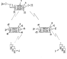
- a first repeater amplifier 1 which has a first input 2 and a first output 4.
- a connection antenna 3 is connected to the first input 2 and receives the high-frequency signals coming from a base station. These signals have a carrier frequency F1.
- a supply antenna 5 is connected to the first output 4 of the repeater amplifier 1.
- Two further repeater amplifiers 8 and 9 are shown under the first repeater amplifier 1. These repeater amplifiers each have a first input 10 or 11 and a first output 12 or 13. A connection antenna 20 or 21 is connected to the first inputs 10 and 11, respectively. To the first Outputs 12 and 13 are connected to a supply antenna 14 and 15, respectively.
- the spatial area which the further repeater amplifiers 8 and 9 can supply with radio signals is limited. In the drawing, the repeater amplifier 8 shown on the left can supply the mobile stations 6 shown below with radio signals, while the repeater amplifier 9 shown on the right can supply the mobile stations 7 shown on the right with radio signals.
- Both further repeater amplifiers 8 and 9 each have a second input 16 and 17 and a second output 18 and 19, respectively. These second inputs 16 and 17 are connected to a receiving antenna 14 and 15, which in the embodiment shown is identical to the supply antennas 14 and 15 of the first outputs 12 and 13 of the further repeater amplifiers 8 and 9.
- the second inputs 16 and 17 are used to receive radio signals from the mobile stations 6 and 7.
- the further repeater amplifiers 8 and 9 have two of the outputs 18 and 19, to which transmit antennas 20 and 21 are connected, which in turn are identical to the connection antennas 20 and 21 for the first inputs 10 and 11 of these repeater amplifiers 8 and 9, respectively.
- the first repeater amplifier 1 also has a further input 23, the receiving antenna 22 of which is also the supply antenna 5 of the first output 4 of this repeater amplifier and a second output 25, the transmitting antenna 24 of which is also the connecting antenna 3 of the first input 2 of this repeater. Amplifier 1 is.
- repeater amplifiers 1, 8 and 9 have devices in both directions for shifting the carrier frequency of the received signals, which are explained in more detail below with reference to the functioning of the repeater arrangement.
- this serves to supply the interiors of buildings which are not directly accessible from the base station can be achieved because the building is made of reinforced concrete, for example, or has metallized panes that form a barrier to radio signals.
- the first repeater amplifier 1 is arranged outside the building, preferably on its roof, and is connected there to a transmitting / connecting antenna 24/3 and to a receiving / supply antenna 22/5.
- the further repeater amplifiers 8 and 9 in fact it can be an unlimited number of further repeater amplifiers, are accommodated, for example, in suitable locations on the different floors of the building, and smaller antennas, namely one connection antenna and one supply antenna, are switched on they connected. In this way, each additional repeater amplifier 8, 9 ... ensures radio coverage for one floor of the building.
- the repeater amplifier works as follows:
- the signals on a carrier frequency F1 of a base station are fed to the first input 2 of the first repeater amplifier 1 mounted on the roof of the building via the connection antenna 3.
- the repeater amplifier 1 amplifies these signals and simultaneously converts the carrier frequency to a frequency F3.
- the signal of the output 4 of the amplifier 1, that is to say the signals converted to the carrier frequency F3, are fed to the supply antenna 5 of the repeater amplifier 1 and from there are transmitted to the further repeater amplifiers 8 and 9 within the building.
- the signals of the mobile station arrive 6 and 7 to the receiving antennas 14 and 15 of the further repeater amplifiers 8 and 9.
- These signals are at a frequency F2 which differs from both the frequency F1 and the frequency F3. They are converted by the further repeater amplifiers 8 and 9 to a further frequency F4 and then fed to the outputs 18 and 19 and the transmitting antennas 20 and 21 of the further repeater amplifiers 8 and 9.
- These signals run wirelessly to the first repeater amplifier 1, from whose reception antenna 22 they are received and fed to the second input 23 of the repeater amplifier 1. This resets the signals lying on a carrier frequency F4 to their original frequency F2 and passes them on via its output 25 and the transmitting antenna 24 to the base station.
- the present arrangement has the advantage that both the first repeater amplifier 1 and the further repeater amplifiers 8 and 9 can each have transmit and receive antennas directly adjacent to one another, since no interference and self-excitation processes occur same frequencies occur.
- the further repeater amplifiers 8 and 9 receive the external signal directly at the carrier frequency F1. Since these repeater amplifiers could possibly also entice the immediate signal of the base station, this signal would then be frequency-shifted and output at an incorrect frequency.
- the further repeater amplifiers 8 and 9 therefore compare the frequency set on them with the frequency information given in the organization channel of the signal. If these two pieces of information are identical, the further repeater amplifier 8 or 9 immediately receives the signal of the base station and searches for another channel. Only if this information is not identical does the further repeater amplifier 8 or 9 receive the frequency-shifted signal of the first repeater amplifier 1 - of course still in its organizational channel carries the frequency information F1 - and because of this deviation knows that it is receiving on the correct frequency.
Landscapes
- Engineering & Computer Science (AREA)
- Computer Networks & Wireless Communication (AREA)
- Signal Processing (AREA)
- Mobile Radio Communication Systems (AREA)
- Radio Relay Systems (AREA)
Applications Claiming Priority (2)
| Application Number | Priority Date | Filing Date | Title |
|---|---|---|---|
| DE19611342 | 1996-03-22 | ||
| DE1996111342 DE19611342A1 (de) | 1996-03-22 | 1996-03-22 | Repeater-Anordnung |
Publications (1)
| Publication Number | Publication Date |
|---|---|
| EP0797320A2 true EP0797320A2 (fr) | 1997-09-24 |
Family
ID=7789098
Family Applications (1)
| Application Number | Title | Priority Date | Filing Date |
|---|---|---|---|
| EP19970103510 Withdrawn EP0797320A2 (fr) | 1996-03-22 | 1997-03-04 | Système répéteur-amplificateur pour réseau de téléphones radiomobiles avec transposition de fréquences porteuses |
Country Status (3)
| Country | Link |
|---|---|
| EP (1) | EP0797320A2 (fr) |
| AU (1) | AU1643797A (fr) |
| DE (1) | DE19611342A1 (fr) |
Cited By (2)
| Publication number | Priority date | Publication date | Assignee | Title |
|---|---|---|---|---|
| CN101207852B (zh) * | 2006-12-21 | 2010-09-15 | 京信通信技术(广州)有限公司 | 自适应消除自激干扰直放站 |
| CN101277479B (zh) * | 2007-03-29 | 2011-07-27 | 京信通信系统(中国)有限公司 | 基带反馈型抗自激模块 |
Families Citing this family (1)
| Publication number | Priority date | Publication date | Assignee | Title |
|---|---|---|---|---|
| DE19950882C2 (de) * | 1999-10-22 | 2001-10-18 | Motorola Inc | Kommunikationssystem für ein Gebiet mit eingeschränkten Empfangsmöglichkeiten |
Family Cites Families (7)
| Publication number | Priority date | Publication date | Assignee | Title |
|---|---|---|---|---|
| GB8629159D0 (en) * | 1986-12-05 | 1987-01-14 | British Telecomm | Mobile radio systems |
| US4941200A (en) * | 1987-08-03 | 1990-07-10 | Orion Industries, Inc. | Booster |
| US5245610A (en) * | 1991-05-20 | 1993-09-14 | Ericsson Ge Mobile Communications, Inc. | Digital radio mobile frequency supervision |
| GB2272599A (en) * | 1992-11-12 | 1994-05-18 | Nokia Telecommunications Oy | A method of cellular radio communication and a cellular radio system for use in such method |
| US5408681A (en) * | 1993-08-16 | 1995-04-18 | The United States Of America As Represented By The Secretary Of The Navy | Automatic repeater station for signal transmissions |
| US5479400A (en) * | 1994-06-06 | 1995-12-26 | Metricom, Inc. | Transceiver sharing between access and backhaul in a wireless digital communication system |
| SE513975C2 (sv) * | 1994-08-19 | 2000-12-04 | Telia Ab | Repeterare och metod för DECT-system |
-
1996
- 1996-03-22 DE DE1996111342 patent/DE19611342A1/de not_active Withdrawn
-
1997
- 1997-03-04 EP EP19970103510 patent/EP0797320A2/fr not_active Withdrawn
- 1997-03-21 AU AU16437/97A patent/AU1643797A/en not_active Abandoned
Cited By (2)
| Publication number | Priority date | Publication date | Assignee | Title |
|---|---|---|---|---|
| CN101207852B (zh) * | 2006-12-21 | 2010-09-15 | 京信通信技术(广州)有限公司 | 自适应消除自激干扰直放站 |
| CN101277479B (zh) * | 2007-03-29 | 2011-07-27 | 京信通信系统(中国)有限公司 | 基带反馈型抗自激模块 |
Also Published As
| Publication number | Publication date |
|---|---|
| AU1643797A (en) | 1997-09-25 |
| DE19611342A1 (de) | 1997-09-25 |
Similar Documents
| Publication | Publication Date | Title |
|---|---|---|
| DE19780990C2 (de) | Vorrichtung und Verfahren zur drahtlosen Nachrichtenübermittlung in einem Versorgungsbereich mit mehreren Sektoren | |
| DE69305530T2 (de) | Rf zwischenstation fur duplex schnurlose telefonanordnung mit zeitmultiplex | |
| DE69032053T2 (de) | Antennen-Umschaltsystem | |
| DE69215372T2 (de) | Antenneneinrichtung für Basisstation | |
| DE2322921C2 (de) | Hochfrequenz-Kommunikationssystem | |
| DE602004012331T2 (de) | Antennen-diversity-anordnung und -verfahren | |
| DE69116949T2 (de) | Verfahren und Vorrichtung zur drahtlosen Kommunikation zwischen entfernten Lagen | |
| DE2631517A1 (de) | Anlage fuer den funkverkehr mit einer in einem den versorgungsbereich einer einzigen festen sende-empfangsstation uebersteigenden gebiet verkehrenden beweglichen station | |
| DE3788867T2 (de) | Bewegliche Funksysteme. | |
| DE69211330T2 (de) | Funksende- und -empfangsanordnung | |
| WO2005081562A1 (fr) | Procede de transmission de donnees a l'interieur d'une station de base de systeme radiotelephonique mobile et station de base correspondante | |
| DE1938805A1 (de) | Nachrichtenuebertragungssystem | |
| EP0166885A2 (fr) | Système de radiotéléphonie | |
| DE60132774T2 (de) | Verbesserte diversitätsversorgung | |
| DE2831056A1 (de) | Nachrichten-uebertragungsanordnung | |
| EP1295402B1 (fr) | Agencement pour faire fonctionner plusieurs terminaux | |
| EP0797320A2 (fr) | Système répéteur-amplificateur pour réseau de téléphones radiomobiles avec transposition de fréquences porteuses | |
| EP0440081A2 (fr) | Système de radio mobile cellulaire | |
| DE2815670C2 (fr) | ||
| DE3203678C2 (fr) | ||
| EP1039650A2 (fr) | Circuit pour compenser de l'attenuation | |
| DE4224422A1 (de) | Relais-Funksystem und Funkgerät dafür | |
| DE19648178A1 (de) | System zur drahtlosen Telephonie, Mobilfunkrepeater und Verfahren zur Funkversorgung für die drahtlose Telephonie | |
| DE60317657T2 (de) | Zugriffsverfahren und umts-zwischenverstärkersystem mit spektralaustausch zwischen umts-wellenfrequenzen | |
| DE2426668C3 (de) | Funksystem für die Abwicklung eines Sprechfunkverkehrs innerhalb eines größeren, in mehrere Bereiche aufgeteilten Gebietes |
Legal Events
| Date | Code | Title | Description |
|---|---|---|---|
| PUAI | Public reference made under article 153(3) epc to a published international application that has entered the european phase |
Free format text: ORIGINAL CODE: 0009012 |
|
| AK | Designated contracting states |
Kind code of ref document: A2 Designated state(s): AT BE CH DE DK ES FI FR GB IE IT LI NL SE |
|
| STAA | Information on the status of an ep patent application or granted ep patent |
Free format text: STATUS: THE APPLICATION HAS BEEN WITHDRAWN |
|
| 18W | Application withdrawn |
Withdrawal date: 20000224 |