EP0797339A2 - Procédé et circuit pour améliorer la caractéristique de transmission d'une liaison de télécommunications perturbée par un écho - Google Patents
Procédé et circuit pour améliorer la caractéristique de transmission d'une liaison de télécommunications perturbée par un écho Download PDFInfo
- Publication number
- EP0797339A2 EP0797339A2 EP97400564A EP97400564A EP0797339A2 EP 0797339 A2 EP0797339 A2 EP 0797339A2 EP 97400564 A EP97400564 A EP 97400564A EP 97400564 A EP97400564 A EP 97400564A EP 0797339 A2 EP0797339 A2 EP 0797339A2
- Authority
- EP
- European Patent Office
- Prior art keywords
- transmission
- path
- compander
- echo
- short
- Prior art date
- Legal status (The legal status is an assumption and is not a legal conclusion. Google has not performed a legal analysis and makes no representation as to the accuracy of the status listed.)
- Granted
Links
Images



Classifications
-
- H—ELECTRICITY
- H04—ELECTRIC COMMUNICATION TECHNIQUE
- H04M—TELEPHONIC COMMUNICATION
- H04M9/00—Arrangements for interconnection not involving centralised switching
- H04M9/08—Two-way loud-speaking telephone systems with means for conditioning the signal, e.g. for suppressing echoes for one or both directions of traffic
- H04M9/082—Two-way loud-speaking telephone systems with means for conditioning the signal, e.g. for suppressing echoes for one or both directions of traffic using echo cancellers
Definitions
- the invention relates to a method and a circuit arrangement for improving the transmission properties of an echo transmission line in a telecommunication network, which consists, for example, of the interconnection of telecommunication systems in analog and digital circuit technology.
- Problems with this interconnection are the transitions from two-wire transmission lines, which are typical for the subscriber lines in analog telecommunications networks, to four-wire transmission lines in digital telecommunications networks.
- These 2-wire / 4-wire transitions are realized with hybrid circuits in which mismatching of the line simulation to the actual properties of the lines can never be completely avoided technically, so that signal reflections occur which, as disturbing echoes, can significantly reduce speech intelligibility between the participants or at data transmission can significantly increase the error rate.
- the so-called local echo which arises from the acoustic coupling between loudspeaker and microphone in hands-free devices, can be considerably reduced with such an echo canceller.
- Mismatched hybrid circuits in telecommunication networks with 2-wire / 4-wire transitions result in an electrical coupling between the transmission path 1.3 and the reception path 1.5 and part of the transmitted signal is sent back to the subscriber as a so-called line echo via the reception path as shown in FIG. 1.
- different transmission media and transmission devices such as satellite routes, subsea cable routes, encryption devices or high-compression audio / video codecs
- echoes with different intensities and delay times result, which roughly result in near echoes and distant echoes be divided.
- a line transmission system with a transmission path and a reception path thus differs significantly from a loudspeaker-room-microphone system, particularly with regard to the different echo propagation times and the different line attenuations.
- adaptive digital filters are preferably used, the filter coefficients of which can be determined and set, for example, according to the Normalized Least Mean Square algorithm, NLMS algorithm for short, cf. T. Hahn, H.-J. Jentschel: Combination of noise reduction and echo cancellation in hands-free mode. Telecommunications Electronics, Berlin 43 (1993), pages 274-280.
- the filter coefficients must be constantly updated in accordance with the changing echo signal. The necessary filter length is determined by the sampling frequency and the longest echo run time.
- the echo delay time is very different and can be more than 250 ms, so that either the number of filter coefficients to be calculated has to be very large or a method for determining the individual echo delay times has to be used, for example a correlation analysis which requires a high computing effort, see. DE 43 05 256 A1. From this publication it is known to carry out a correlation measurement between the received echo signal and the transmitted signal in order to determine the exact point in time for the determination of the echo propagation times and the filter coefficients. However, the practical application of this solution fails because the effort is too great.
- companders with which transmission signals above a setpoint are compressed to a uniform signal level, provided that they have the setpoint, amplified and as far as they are below the setpoint, attenuated.
- a circuit arrangement for dynamic control of a terminal device which is described in the patent specification DE 37 24 346 A1
- the degree of amplification for the signal voltages supplied by a microphone is adjusted to the desired value with a controllable compander. This ensures that fluctuations in the microphone signal caused by moderate changes in the discussion distance and individual speech volume arise, are compressed to a more even volume level on the playback side.
- a method for improving the transmission properties of an electroacoustic system with which the position of the compander characteristic is automatically controlled, cf. DE 42 29 912 A1.
- the method detects whether the transmission signal originates from speech or from noise.
- the control variable for the companding characteristic generated from the speech and noise detection it is achieved that the speech to be transmitted is transmitted at a constant level, that the background noise level for the transmission is lowered and that the reproduction reception volume is increased with increasing ambient noise.
- the method can be implemented inexpensively, since neither digital filters with a large number of filter coefficients nor complex correlation measurements are required.
- FIG. 1 a typical transmission path between a local subscriber A and a remote subscriber B is shown in FIG. 1.
- a terminal 1 On the side of the local subscriber A there is a terminal 1 and possibly a hands-free device 2, a line echo suppressor 3 and a first hybrid circuit 4. The different transit times of the signals through the network are symbolized by block 5.
- a second hybrid circuit 6 At the far end of the transmission path there is a second hybrid circuit 6 and possibly a hands-free device 7 for the terminal 8 of the remote subscriber B.
- the hands-free device 2 of the local subscriber A contains an echo canceller, for example consisting of an adaptive echo filter and a hands-free compander, for suppressing the local echoes 8.1 that arise due to the acoustic coupling between the loudspeaker 1.1 and the microphone 1.2 when messages from the distant subscriber B are received .
- an echo canceller for example consisting of an adaptive echo filter and a hands-free compander, for suppressing the local echoes 8.1 that arise due to the acoustic coupling between the loudspeaker 1.1 and the microphone 1.2 when messages from the distant subscriber B are received .
- the line echoes 4.1, 6.1 that arise in the first hybrid circuit 4 and in the second hybrid circuit 6, which arise during the transmission of signals from the local subscriber A to the remote subscriber B, are suppressed.
- the echo which arises in the first hybrid circuit 4 is referred to as the near echo 4.1 and is characterized by a short, essentially constant transit time.
- the echo which arises in the second hybrid circuit 6 is referred to as the remote echo 6.1 and, due to very different transmission means, such as, for example, cables and / or satellite links, has very different transit times.
- very different transmission means such as, for example, cables and / or satellite links
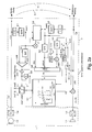
- the line echo suppressor 3 essentially consists of a compander 3.7 with a control circuit comprising a coupling estimator 3.6, a first integrator 3.1, a second integrator 3.2, a third integrator 3.3, a fourth integrator 3.4 and a fifth integrator 3.5, and also a maximum value decision maker 3.8.
- the line echo canceller 3 is connected to a local terminal 1, i.e. with its microphone 1.2 via an analog / digital converter 1.4 in the transmission path 1.3 and with its playback part with a digital / analog converter 1.6 and earpiece 1.1 in the reception path 1.5.
- the transmission path 1.3 is electrically coupled by non-adapted hybrid circuits 4, 6 according to FIG. 1 via the near echo 4.1 and via the far echo 6.1 to the reception path 1.5, via which the received signals during speech transmission are transmitted to a digital / analog converter 1.6 with a downstream earphone 1.1 be fed.
- FIGS. 3a, 3b, 3c show different companding characteristics which can be used for different requirements.
- a control value us which is in the range usmin ⁇ us ⁇ usmax, defines the various characteristic curve positions.
- the input value ysam represents the short-term mean value of the scan sequence y (k) of the received signal
- the output value youtsam represents the short-term mean value of the scan sequence yout (k) of the output signal.
- the quotient of the output value youtsam and the input value ysam indicates the gain factor VS.
- the electrical coupling between the transmission path 1.3 and the reception path 1.5 is estimated for the near echo 4.1.
- the scanning sequence x (k) of the transmission signal with the first integrator 3.1 a short-time average value (s hort-time a verage m agnitude) xsam the transmit signal and from the sampling sequence y (k) of the received signal to the second integrator 3.2 a short-time mean value of the reception signal ysam formed.
- the minimum electrical coupling factor dll between transmission path 1.3 and reception path 1.5 is determined in successive time intervals I, for example I ⁇ 5s, which is evaluated with the short-term mean value xsam of the transmission signal and a control signal thrs for the compander characteristic delivers.
- the coupling factor dll is only estimated when the local subscriber A is speaking.
- a is us the short-time average xsam of the transmission signal to the fourth integrator 3.4, a long-time average value (l ong-time a verage m agnitude) xlam formed.
- the short-term mean value xsam of the transmit signal is greater than the long-term mean value xlam of the transmit signal, this is a characteristic of the local subscriber A speaking; the briefly rising speech level stands out from the noise level. This results in the possibility of distinguishing speech, which is generally characterized by high dynamics, from a generally more uniform ambient noise.
- a long-term mean ynlam is formed from the short-term mean ysam of the received signal by means of the third integrator 3.3, which is a measure of the noise level on the receive path 1.5.
- the coupling values dll for the near echo and the transit time of the near echoes are relatively small in practical cases, and the noise level on the reception path can also be small, so that the control value us is at small input values ysam in order for the local subscriber A to be able to use it Speech only covered attenuating near echo to such an extent that unpleasant listening back is prevented.
- the state can now occur that the speech level of the distant subscriber B is far in the compression range of the companding characteristic and the level of the far echo at a distance from the speech level of, for example, 17 dB is also still in the compression range of the companding characteristic and is thus passed through.
- the distant echo is to be suppressed, however, so that, according to the invention, a shift in the characteristic curve is additionally made dependent on the size of the speech level of the distant subscriber B on the reception path 1.5.
- a long-term mean value yslam weighted by a factor Xuso is formed from the sampling sequence y (k) of the received signal with the fifth integrator 3.5.
- the maximum value decision 3.8 determines whether the coupling at the near end of the line, the noise level or the speech level of the reception path is dominant for determining the position of the companding characteristic.
- the position of the voltage value us is regulated by the weighting factor Xuso in such a way that the speech level of the remote subscriber B lies in the transition area between expansion and compression, that is, according to FIG Points P2 and P3 and drawn in as the working point. If there is no speech level on the reception path 1.5, the size of the previously determined long-term mean yslam is retained until a speech level of the remote subscriber B is evaluated again.
- the stroke of the linear initial part of the companding characteristic ie the steepness of the expander
- FIG. 3b two Kompander characteristics with a stroke 1 and a stroke 2 are shown.
- the stroke is the distance between the linearly increasing initial part of the companding curve and a parallel, which is also tangent to the transition area from expansion to compression.
- this stroke must on the one hand be set so large that no disturbing echo is transmitted, on the other hand it should be so small that the background noise is not completely suppressed by the remote subscriber B, so that there is no impression of an interrupted connection.
- the smoother transition into the compression range of the compander characteristic curve leads to a more natural speech impression when speech is used.
- the larger hub 2 is set with a companding characteristic curve exp2, since distant echoes can now be expected and are to be suppressed.
- the control signal S switches from the large hub 2 to the small hub 1 with a time delay via a delay circuit 3.9 with a time ⁇ , since echoes can still be expected after the end of the speech.
- This stroke reversal can advantageously also be used in hands-free devices in which the compander lies in the transmission path.
- a large hub 2 is set to suppress the local echoes.
- the reset to the small hub 1 can then take place without delay because of the short duration of the local echo.
- This new type of companding characteristic has the effect that voice signals from remote subscriber B, which are strongly attenuated, are also received quietly and signals with lower attenuation are correspondingly louder.
- the line losses are compensated for poor connections, and the reception volume of the speech is kept largely independent of the transmission level of the remote subscriber B and the line loss.
- FIG. 2b shows a possible implementation for compander 3.7.
- the circuit arrangement required for this essentially consists of a multiplier 3.71, a changeover switch 3.72, an integrator 3.73 and an inverter 3.74.
- the position of the changeover switch 3.72 is determined by the current relation between the magnitude of the scanning sequence of the input signal y (k) and the voltage value us.
- the position of the switch 3.72 shown in FIG. 2b is assumed when the magnitude of the scanning sequence of the received signal y (k) is greater than the voltage value us.
- the long-term mean value of the received signal ysam is then fed to the integrator 3.73. If the magnitude of the sampling sequence of the received signal y (k) is less than the voltage value us, the voltage value us multiplied by the current stroke value of the companding characteristic curve exp 1 or exp 2 reaches the integrator 3.73.
- the output signal of the changeover switch 3.73 is integrated with rising pulse edges with a small time constant, for example 6 ms, and with falling pulse edges with a larger time constant, for example 60 ms.
- the reciprocal value is formed with the inverter 3.74, which represents the gain VS of the compander, which is dependent on the current situation, by which the scanning sequence y (k) of the received signal is multiplied and thus the scanning sequence yout (k) of the Output signal of the power echo canceller 3 provides.
- the exemplary embodiment relates to voice transmission, it is, however, easily possible to use the method and the circuit arrangement even if, for example, a data transmission is carried out with the aid of a modem. In this case, the suppression of echoes increases the security of the transmission and reduces the error rate.
- the circuit arrangement can be used at different points on the transmission path.
- a hands-free device it can be used in a communication terminal, so that both local echoes and line echoes are suppressed.
- transmission paths with mixed four-wire lines with digital technology and two-wire lines with analog technology, with or without local hands-free devices, with or without signal processing systems, such as codecs and satellite links, can occur.
- Another possible application is central, for example in a base station of a radio switching system based on the GSM or DECT standard.
- a base station of a radio switching system based on the GSM or DECT standard.
- several identical circuit arrangements can be used, which are assigned to a communication link in the public network as required. Because of the low complexity for the circuit arrangement, it is possible to implement, for example, eight circuit arrangements with only one digital signal processor.
- circuit arrangement can be arranged centrally, for example in a switching center, where it can be switched into a transmission link if required.
- the line echo canceller 3 can be combined with a short adaptive filter 3a according to FIG. 4 for echo suppression of close echoes.
- the effect of the adaptive filter is to suppress the near echoes from the line as well as possible, so that overall a system gain is achieved since the tolerances for the setting of the compander characteristic of the line echo canceller 3 can then be somewhat larger.
- the adaptive filter can have a relatively short length of, for example, less than 100 memory elements, since it only needs to reduce the very close echoes of the line.
- the short adaptive filter is set in a known manner according to the normalized least mean square algorithm, it being possible advantageously for the control criteria for the compander to also be used for controlling the step size a in the algorithm mentioned for the adaptive filter.
- control criteria for the compander it is also possible to use the control criteria for the compander to control a variably adjustable attenuator for echo blanking.
- the circuit arrangement according to the invention if necessary combined with a short adaptive filter, can be used in conjunction with a hands-free device made from a hands-free compander and, if necessary, an adaptive filter, so that a substantial improvement in the communication properties of an echo-affected transmission path in both transmission directions is then achieved.
Landscapes
- Engineering & Computer Science (AREA)
- Signal Processing (AREA)
- Cable Transmission Systems, Equalization Of Radio And Reduction Of Echo (AREA)
- Circuit For Audible Band Transducer (AREA)
Applications Claiming Priority (2)
| Application Number | Priority Date | Filing Date | Title |
|---|---|---|---|
| DE19611548A DE19611548A1 (de) | 1996-03-23 | 1996-03-23 | Verfahren und Schaltungsanordnung zur Verbesserung der Übertragungseigenschaften einer echobehafteten Übertragungsstrecke in einem Telekommunikationsnetz |
| DE19611548 | 1996-03-23 |
Publications (3)
| Publication Number | Publication Date |
|---|---|
| EP0797339A2 true EP0797339A2 (fr) | 1997-09-24 |
| EP0797339A3 EP0797339A3 (fr) | 2003-07-16 |
| EP0797339B1 EP0797339B1 (fr) | 2004-12-29 |
Family
ID=7789220
Family Applications (1)
| Application Number | Title | Priority Date | Filing Date |
|---|---|---|---|
| EP97400564A Expired - Lifetime EP0797339B1 (fr) | 1996-03-23 | 1997-03-14 | Procédé et circuit pour améliorer la caractéristique de transmission d'une liaison de télécommunications perturbée par un écho |
Country Status (5)
| Country | Link |
|---|---|
| US (1) | US5909489A (fr) |
| EP (1) | EP0797339B1 (fr) |
| JP (1) | JPH1056687A (fr) |
| AT (1) | ATE286336T1 (fr) |
| DE (2) | DE19611548A1 (fr) |
Cited By (1)
| Publication number | Priority date | Publication date | Assignee | Title |
|---|---|---|---|---|
| WO2000060830A3 (fr) * | 1999-03-30 | 2001-08-02 | Siemens Ag | Telephone mobile |
Families Citing this family (13)
| Publication number | Priority date | Publication date | Assignee | Title |
|---|---|---|---|---|
| US6160886A (en) * | 1996-12-31 | 2000-12-12 | Ericsson Inc. | Methods and apparatus for improved echo suppression in communications systems |
| DE19815942A1 (de) | 1998-04-09 | 1999-10-14 | Cit Alcatel | Vielkanal-Echocanceller mit Compander |
| DE19825196A1 (de) * | 1998-06-05 | 1999-12-09 | Alcatel Sa | Verfahren zur Kopplungsbestimmung zwischen zwei Telekommunikations(=TK)-Wegen |
| DE19928045A1 (de) * | 1999-06-18 | 2000-12-28 | Alcatel Sa | Verfahren und Schaltungsanordnung zur Echokompensation in einem Telekommunikationssystem mit nichtlinearen Übertragungsstrecken |
| US6988236B2 (en) * | 2000-04-07 | 2006-01-17 | Broadcom Corporation | Method for selecting frame encoding parameters in a frame-based communications network |
| DE10119277A1 (de) * | 2001-04-20 | 2002-10-24 | Alcatel Sa | Verfahren zur Maskierung von Geräuschmodulationen und Störgeräuschen bei der Sprachübertragung |
| US7010118B2 (en) * | 2001-09-21 | 2006-03-07 | Agere Systems, Inc. | Noise compensation methods and systems for increasing the clarity of voice communications |
| US20060184361A1 (en) * | 2003-04-08 | 2006-08-17 | Markus Lieb | Method and apparatus for reducing an interference noise signal fraction in a microphone signal |
| DE10329055B4 (de) * | 2003-06-27 | 2005-10-13 | Infineon Technologies Ag | Verfahren und Vorrichtung zur Echokompensation |
| JP2006203357A (ja) * | 2005-01-18 | 2006-08-03 | Oki Electric Ind Co Ltd | エコーキャンセラ |
| US8497940B2 (en) * | 2010-11-16 | 2013-07-30 | Audio-Technica U.S., Inc. | High density wireless system |
| GB2525947B (en) * | 2014-10-31 | 2016-06-22 | Imagination Tech Ltd | Automatic tuning of a gain controller |
| CN112332881B (zh) * | 2020-10-19 | 2022-04-26 | 深圳市信锐网科技术有限公司 | 使能电路及通信装置 |
Family Cites Families (8)
| Publication number | Priority date | Publication date | Assignee | Title |
|---|---|---|---|---|
| EP0290952B1 (fr) * | 1987-05-15 | 1992-11-04 | Alcatel SEL Aktiengesellschaft | Montage pour commande de la parole pour un terminal de télécommunication |
| US4979163A (en) * | 1988-12-28 | 1990-12-18 | At&T Bell Laboratories | Echo suppression arrangement for an adaptive speakerphone |
| DE4130045A1 (de) * | 1991-09-10 | 1993-03-18 | Standard Elektrik Lorenz Ag | Schaltungsanordnung zur dynamiksteuerung eines sprachendgeraetes |
| DE4229912A1 (de) * | 1992-09-08 | 1994-03-10 | Sel Alcatel Ag | Verfahren zum Verbessern der Übertragungseigenschaften einer elektroakustischen Anlage |
| DE4229910A1 (de) * | 1992-09-08 | 1994-03-10 | Sel Alcatel Ag | Verfahren zum Verbessern der akustischen Rückhördämpfung von elektroakustischen Anlagen |
| DE4305256A1 (de) * | 1993-02-20 | 1994-08-25 | Sel Alcatel Ag | Verfahren zum Verbessern der akustischen Rückhördämpfung von elektroakustischen Anlagen |
| DE4313256A1 (de) * | 1993-04-23 | 1994-10-27 | Sel Alcatel Ag | Verfahren zum Unterdrücken von Rückkopplungen bei Saal- oder Großfeldbeschallungsanlagen und Schaltungsanordnung zur Ausführung des Verfahrens |
| DE4430189A1 (de) * | 1994-08-25 | 1996-02-29 | Sel Alcatel Ag | Verfahren zur adaptiven Echokompensation |
-
1996
- 1996-03-23 DE DE19611548A patent/DE19611548A1/de not_active Withdrawn
-
1997
- 1997-03-14 DE DE59712139T patent/DE59712139D1/de not_active Expired - Fee Related
- 1997-03-14 AT AT97400564T patent/ATE286336T1/de not_active IP Right Cessation
- 1997-03-14 EP EP97400564A patent/EP0797339B1/fr not_active Expired - Lifetime
- 1997-03-21 US US08/828,191 patent/US5909489A/en not_active Expired - Fee Related
- 1997-03-24 JP JP9087222A patent/JPH1056687A/ja not_active Withdrawn
Cited By (1)
| Publication number | Priority date | Publication date | Assignee | Title |
|---|---|---|---|---|
| WO2000060830A3 (fr) * | 1999-03-30 | 2001-08-02 | Siemens Ag | Telephone mobile |
Also Published As
| Publication number | Publication date |
|---|---|
| US5909489A (en) | 1999-06-01 |
| JPH1056687A (ja) | 1998-02-24 |
| DE59712139D1 (de) | 2005-02-03 |
| DE19611548A1 (de) | 1997-09-25 |
| EP0797339A3 (fr) | 2003-07-16 |
| ATE286336T1 (de) | 2005-01-15 |
| EP0797339B1 (fr) | 2004-12-29 |
Similar Documents
| Publication | Publication Date | Title |
|---|---|---|
| DE69632851T2 (de) | Akustischer Teilband-Echokompensator | |
| DE60124501T2 (de) | Verbessertes verfahren und vorrichtung zur implementierung eines echounterdrückers | |
| DE69332309T2 (de) | Ausfallgesichertes betriebsverfahren in einem lautfernsprechsystem | |
| EP0742664B1 (fr) | Méthode pour parler à main levée pour un système de transmission à canaux multiples | |
| DE69221949T2 (de) | Verfahren und Einrichtung zur Echokompensation in einem digitalen Fernmeldesystem | |
| DE69835347T2 (de) | Mehrfacheingang drahtlostelefon mit echounterdrückung | |
| DE69636570T2 (de) | Echokompensation und -unterdrückung | |
| EP0797339B1 (fr) | Procédé et circuit pour améliorer la caractéristique de transmission d'une liaison de télécommunications perturbée par un écho | |
| DE19848588B4 (de) | Nichtlinearer Prozessor für akustische Echokompensatoren | |
| EP1745637B1 (fr) | Terminal de conference a reduction d'echo pour un systeme de conference | |
| DE1537650A1 (de) | Ein System der selektiven Echounterdrueckung und Laermpegelverminderung in Fernsprechkreisen sowie Vorrichtung zu seiner Ausfuehrung | |
| DE60106582T2 (de) | Verfahren und vorrichtung für stereoechounterdrückung in einen voip-kommunikationsystemen | |
| EP1126687A2 (fr) | Procede pour la reduction coordonnée de bruit et/ou d'écho | |
| EP1155561B1 (fr) | Dispositif et procede de suppression de bruit dans des installations telephoniques | |
| DE2856789A1 (de) | Echounterdrueckungs-schaltkreis | |
| DE19848641B4 (de) | Doppelsprech-unempfindlicher NLMS Algorithmus | |
| DE69132988T2 (de) | Verfahren für aktive rückkopplunglsunterdrückung | |
| DE69728150T2 (de) | Dynamische optimierung für mikrofonverstärkung in einer freisprecheinrichtung | |
| DE2457876A1 (de) | Echounterdruecker fuer ein endgeraet einer elektrischen vierdrahtleitung | |
| EP0784395A2 (fr) | Téléphone mobile | |
| DE3839627C2 (de) | Fernsprechendgerät | |
| DE2633394A1 (de) | Verfahren zur kompensation von akustischer rueckkopplung in freisprechanlagen | |
| EP0949767A2 (fr) | Annuleur d'échos à canaux multiple avec compresseur-extenseur | |
| EP0992151B1 (fr) | Procede et dispositif permettant d'attenuer l'echo dans un dispositif mains libres, tel qu'un telephone | |
| DE19537772A1 (de) | Freisprecheinrichtung für ein Fernsprechendgerät |
Legal Events
| Date | Code | Title | Description |
|---|---|---|---|
| PUAI | Public reference made under article 153(3) epc to a published international application that has entered the european phase |
Free format text: ORIGINAL CODE: 0009012 |
|
| AK | Designated contracting states |
Kind code of ref document: A2 Designated state(s): AT BE CH DE ES FR GB IT LI NL SE |
|
| RAP3 | Party data changed (applicant data changed or rights of an application transferred) |
Owner name: ALCATEL |
|
| RAP3 | Party data changed (applicant data changed or rights of an application transferred) |
Owner name: ALCATEL |
|
| PUAL | Search report despatched |
Free format text: ORIGINAL CODE: 0009013 |
|
| AK | Designated contracting states |
Designated state(s): AT BE CH DE ES FR GB IT LI NL SE |
|
| RIC1 | Information provided on ipc code assigned before grant |
Ipc: 7H 04R 3/02 B Ipc: 7H 03G 7/00 B Ipc: 7H 03G 3/32 B Ipc: 7H 04B 3/20 B Ipc: 7H 04M 9/08 A |
|
| 17P | Request for examination filed |
Effective date: 20030616 |
|
| 17Q | First examination report despatched |
Effective date: 20030825 |
|
| GRAP | Despatch of communication of intention to grant a patent |
Free format text: ORIGINAL CODE: EPIDOSNIGR1 |
|
| GRAS | Grant fee paid |
Free format text: ORIGINAL CODE: EPIDOSNIGR3 |
|
| GRAA | (expected) grant |
Free format text: ORIGINAL CODE: 0009210 |
|
| AK | Designated contracting states |
Kind code of ref document: B1 Designated state(s): AT BE CH DE ES FR GB IT LI NL SE |
|
| PG25 | Lapsed in a contracting state [announced via postgrant information from national office to epo] |
Ref country code: NL Free format text: LAPSE BECAUSE OF FAILURE TO SUBMIT A TRANSLATION OF THE DESCRIPTION OR TO PAY THE FEE WITHIN THE PRESCRIBED TIME-LIMIT Effective date: 20041229 |
|
| REG | Reference to a national code |
Ref country code: GB Ref legal event code: FG4D Free format text: NOT ENGLISH |
|
| REG | Reference to a national code |
Ref country code: CH Ref legal event code: EP |
|
| GBT | Gb: translation of ep patent filed (gb section 77(6)(a)/1977) |
Effective date: 20041230 |
|
| REF | Corresponds to: |
Ref document number: 59712139 Country of ref document: DE Date of ref document: 20050203 Kind code of ref document: P |
|
| PG25 | Lapsed in a contracting state [announced via postgrant information from national office to epo] |
Ref country code: AT Free format text: LAPSE BECAUSE OF NON-PAYMENT OF DUE FEES Effective date: 20050314 |
|
| PG25 | Lapsed in a contracting state [announced via postgrant information from national office to epo] |
Ref country code: SE Free format text: LAPSE BECAUSE OF FAILURE TO SUBMIT A TRANSLATION OF THE DESCRIPTION OR TO PAY THE FEE WITHIN THE PRESCRIBED TIME-LIMIT Effective date: 20050329 |
|
| PG25 | Lapsed in a contracting state [announced via postgrant information from national office to epo] |
Ref country code: LI Free format text: LAPSE BECAUSE OF NON-PAYMENT OF DUE FEES Effective date: 20050331 Ref country code: CH Free format text: LAPSE BECAUSE OF NON-PAYMENT OF DUE FEES Effective date: 20050331 Ref country code: BE Free format text: LAPSE BECAUSE OF NON-PAYMENT OF DUE FEES Effective date: 20050331 |
|
| PG25 | Lapsed in a contracting state [announced via postgrant information from national office to epo] |
Ref country code: ES Free format text: LAPSE BECAUSE OF FAILURE TO SUBMIT A TRANSLATION OF THE DESCRIPTION OR TO PAY THE FEE WITHIN THE PRESCRIBED TIME-LIMIT Effective date: 20050409 |
|
| NLV1 | Nl: lapsed or annulled due to failure to fulfill the requirements of art. 29p and 29m of the patents act | ||
| BERE | Be: lapsed |
Owner name: ALCATEL Effective date: 20050331 |
|
| PLBE | No opposition filed within time limit |
Free format text: ORIGINAL CODE: 0009261 |
|
| STAA | Information on the status of an ep patent application or granted ep patent |
Free format text: STATUS: NO OPPOSITION FILED WITHIN TIME LIMIT |
|
| REG | Reference to a national code |
Ref country code: CH Ref legal event code: PL |
|
| 26N | No opposition filed |
Effective date: 20050930 |
|
| ET | Fr: translation filed | ||
| PGFP | Annual fee paid to national office [announced via postgrant information from national office to epo] |
Ref country code: IT Payment date: 20060331 Year of fee payment: 10 |
|
| PGFP | Annual fee paid to national office [announced via postgrant information from national office to epo] |
Ref country code: DE Payment date: 20070316 Year of fee payment: 11 |
|
| PGFP | Annual fee paid to national office [announced via postgrant information from national office to epo] |
Ref country code: GB Payment date: 20070322 Year of fee payment: 11 |
|
| BERE | Be: lapsed |
Owner name: *ALCATEL Effective date: 20050331 |
|
| PGFP | Annual fee paid to national office [announced via postgrant information from national office to epo] |
Ref country code: FR Payment date: 20070319 Year of fee payment: 11 |
|
| GBPC | Gb: european patent ceased through non-payment of renewal fee |
Effective date: 20080314 |
|
| REG | Reference to a national code |
Ref country code: FR Ref legal event code: ST Effective date: 20081125 |
|
| PG25 | Lapsed in a contracting state [announced via postgrant information from national office to epo] |
Ref country code: DE Free format text: LAPSE BECAUSE OF NON-PAYMENT OF DUE FEES Effective date: 20081001 |
|
| PG25 | Lapsed in a contracting state [announced via postgrant information from national office to epo] |
Ref country code: FR Free format text: LAPSE BECAUSE OF NON-PAYMENT OF DUE FEES Effective date: 20080331 |
|
| PG25 | Lapsed in a contracting state [announced via postgrant information from national office to epo] |
Ref country code: GB Free format text: LAPSE BECAUSE OF NON-PAYMENT OF DUE FEES Effective date: 20080314 |
|
| PG25 | Lapsed in a contracting state [announced via postgrant information from national office to epo] |
Ref country code: IT Free format text: LAPSE BECAUSE OF NON-PAYMENT OF DUE FEES Effective date: 20070314 |