EP0797347A2 - Bildaufzeichnungsgerät mit einer Bildverarbeitungseinheit mit mehreren parallel angeordneten Filtern - Google Patents
Bildaufzeichnungsgerät mit einer Bildverarbeitungseinheit mit mehreren parallel angeordneten Filtern Download PDFInfo
- Publication number
- EP0797347A2 EP0797347A2 EP97103893A EP97103893A EP0797347A2 EP 0797347 A2 EP0797347 A2 EP 0797347A2 EP 97103893 A EP97103893 A EP 97103893A EP 97103893 A EP97103893 A EP 97103893A EP 0797347 A2 EP0797347 A2 EP 0797347A2
- Authority
- EP
- European Patent Office
- Prior art keywords
- image forming
- result
- processing
- image
- pass filter
- Prior art date
- Legal status (The legal status is an assumption and is not a legal conclusion. Google has not performed a legal analysis and makes no representation as to the accuracy of the status listed.)
- Withdrawn
Links
Images



Classifications
-
- H—ELECTRICITY
- H04—ELECTRIC COMMUNICATION TECHNIQUE
- H04N—PICTORIAL COMMUNICATION, e.g. TELEVISION
- H04N1/00—Scanning, transmission or reproduction of documents or the like, e.g. facsimile transmission; Details thereof
- H04N1/40—Picture signal circuits
- H04N1/409—Edge or detail enhancement; Noise or error suppression
- H04N1/4092—Edge or detail enhancement
Definitions
- the present invention relates to an image forming apparatus such as a digital copy machine, which reads an image on an original sheet, processes the read image by an image processing device, and forms the image on a sheet.
- image forming apparatus such as digital copy machines and facsimile devices have been rapidly popularized.
- the image input/output apparatus such as digital copy machines and facsimile devices
- the image input/output apparatus entail the problems of various types of deteriorations of space frequency as follows: the deterioration of the MTF (modulation transfer function) characteristics of the optical system for reading, and the generation of folded distortion caused by the limitation of the frequency band for digital sampling, which take place during the data inputting; the deterioration in the developing system; the generation of moire which is unique to digital process, and the like.
- MTF modulation transfer function
- the image processing device requires an MTF correction.
- filtering process is called “filtering process”, which is further divided into a low pass filtering (to be abbreviated as LPF) for suppressing moire and the like, and a high pass filtering (to be abbreviated as HPF) for emphasizing an edge or the like, of a character.
- LPF low pass filtering
- HPF high pass filtering
- the LPF and HPF are carried out one at a time in series in the course of the flow of the entire image process, that is, an input image is subjected first to the LPF, then to the range correction process for correcting the contrast of the image, and to the HPF.
- the filtering process of a digital copying machine, facsimile or the like is performed through a two-dimensional digital filtering process in the main scanning and the sub-scanning directions. More specifically, the filtering process is performed by multiplying each pixel of a local region consisting of a pixel to be processed (focused pixel) and peripheral pixels, by a coefficient which corresponds to a respective pixel.
- the process in the sub-scanning direction requires line buffers of n lines.
- the filtering process is carried out by the conventional method, the process is performed in a serial manner, and therefore in the case of the LPF and HPF process of a mask size of (3 ⁇ 3), line buffers of a total of 4 lines, two lines for each, are required.
- the object of the present invention is to provide an image forming apparatus capable of reducing the number of line buffers used in the filtering process carried out by a mask size of (n ⁇ n).
- an image forming apparatus including: means for reading image data from an original sheet; first processing means for processing the image data read by the reading means through a low pass filter, and outputting a first process result; second processing means, provided in parallel with the first processing means, for processing the image data read by the reading means through a high pass filter having a filter frequency range higher than that of the low pass filter, and outputting a second process result; adding means for adding up the first process result and the second process result, and outputting a result of addition; and image forming means for forming an image on the basis of the result of addition.
- the present invention exhibits the following advantage. That is, the present invention does not employ the structure of the conventional technique, in which a plurality of filtering processes are arranged in series, and each filtering process is carried out one at a time in sequence, but according to the present invention, a plurality of filtering processes are carried out in a parallel manner for image data.
- a plurality of filtering processes are carried out in a parallel manner for image data.
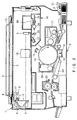
- FIG. 2 is a cross sectional view of an example of the internal structure of a digital copying machine, which is an embodiment of the image forming apparatus according to the present invention.
- the digital copying machine includes a scanner unit 1 for optically reading image data on an original O, and a printer unit 2 for outputting an image read via the scanner unit 1 on a recording medium, which is a copy sheet P.
- an original to be copied is placed on an original placement table 3, and the original O placed on the original placement table 3, is irradiated by a fluorescent lamp 4 extended in the sub-scanning direction, which serves as a light source.
- the light beam reflected from the original O irradiated by the fluorescent lamp 4 is photoelectrically converted by a CCD sensor 5 which serves as a photoelectric conversion element, and thus the image data of the reflection light beam is converted into an image signal.
- a reflector 6 is provided so as to converge the illumination light from the fluorescent lamp 4 on the original O at a high efficiency. Further, between the fluorescent lamp 4 and the CCD sensor 5, a plurality of mirrors for bending optical paths through which light beams reflected from the original O pass, which proceed towards the CCD sensor 5 from the original O, a lens 10 for converging the reflection light beams on the light converging surface of the CCD sensor 5, and the like are provided.
- the optical system for guiding the reflection light beams from the exposure lamp 4 and the original O to the CCD sensor 5 is provided on the carriages 11 and 12, and are conveyed in the main scanning direction by means of a pulse motor which is not shown.
- the sub-scanning directional area of the original O is irradiated by the fluorescent lamp 4, and the sub-scanning directional regions of the original O is sequentially irradiated as the carriages 11 and 12 are conveyed in the main scanning direction.
- the entire region of the original O is irradiated by the fluorescent lamp 4.
- a original sheet cover 13 is provided for bringing the original O into tight contact with the placement table 3.
- the original sheet press cover can be replaced by, for example, an SDF, a semi-automatic original sheet feeding device, or an ADF, an automatic original sheet feeding device, in accordance with the size or performance of the digital copying machine.
- a cylindrical photosensitive drum 14 which can be rotated in a desired direction by means of, for example, a motor (not shown) and is charged at a pre-determined potential, is provided.
- a laser beam is applied on the photosensitive drum 14, the potential of the beam-applied region on the drum, is varied, and a static latent image is formed on the photosensitive drum 14.
- a charging device 15 for applying a predetermined potential to the photosensitive drum 14, a laser unit 16 for outputting a laser beam modulated in accordance with the image data, on the photosensitive drum 14, a developing device for developing a static latent image formed on the photosensitive drum 14 by the laser beam output from the laser unit 16, by supplying a visualizer, that is, toner, to the image, a transfer device 18 for transferring a toner image visualized on the photosensitive drum 14 by development by the developing device 17, on a recording medium, that is, a copy sheet P which is fed from a recording medium feeding unit, which will be explained later, and a removing device 19 for removing the copy sheet P from the photosensitive drum 14.
- the laser unit 16 consists of a semiconductor laser oscillator for generating a laser beam, a polygon mirror 25 for converting the laser beam supplied from the semiconductor laser oscillator 24 via a collimate lens (not shown) into beams of scanning lines, each beam for one scanning line, an f ⁇ lens 26 for converting the laser beams of scanning lines from the polygon mirror 25, into parallel light beams, a mirror 27 for reflecting the parallel light beams from the lens 26 so as to guide them to the photosensitive drum 14, and a mirror motor 28 for rotating the polygon mirror 25.
- a cleaner unit 20 is provided for the purpose of removing toner remaining on the surface of the photosensitive drum 14, and erasing the variance in potential created on the photosensitive drum 14 by the laser beam, for the next image forming operation.
- a fixing device 22 for fixing the toner image on the copy sheet is provided.
- a conveying device 23 for conveying copy sheets P to the fixing device 22 is provided.
- FIG. 3 is a block diagram showing an example of the control system of the copying machine shown in FIG. 2.
- a calculation unit 44 for performing various types of calculations, and four sub-control units 32 to 34 each for executing the control of a respective unit, are connected to a main control unit 31 which controls the overall operation of the digital copying machine.
- the main control unit 31 is connected to an operation panel 35 for instructing various types of image processing, a region management unit 36 for managing an image processing region, and an image processing unit 37 serving as an image processing device for improving the quality of image data inputted, editing the image data, and processing the image data, and the control unit 31 serves to control these members.
- the sub-control unit 32 is connected to a light source control unit 40 for controlling the source light intensity of the fluorescent lamp 4, a mechanism driving unit 42 for controlling a mechanical input mechanism 41 such as the sheet feeding unit shown in FIG. 2, and an A/D conversion unit 43 for converting analog image data converted by the CCD sensor 5 for converting detected reflection light into image data, into a digital data signal, and the sub-control unit 32 serves to control these members.
- the sub-control unit 33 is connected to an image expanding unit 45 for expanding edited or processed image data, for forming an image, and also storing the data, an image output unit 46 for outputting image data from the image expanding unit 45 (image data from the scanner unit 1) in the form of a pulse signal as a laser modulation signal (image data for the printer unit 2), and a mechanism drive unit 49 for driving an output unit mechanism 48 including drive systems such as motor and solenoid in the laser unit 16, and the sub-control unit 33 serves to control these members.
- the sub-control unit 34 is connected to a data transmission/reception unit 50, and the unit 34 controls the transmission/reception of data with regard to an external devices.
- an original O is illuminated by the fluorescent lamp 4, and the reflection light reflected from the original O forms an image on the CCD sensor 5, where the image is converted into an analog electric signal.
- the analog image signal is converted into a digital signal by the A/D converting unit 43, and the digital signal converted is output to the image processing unit 37.
- the image processing unit 37 performs, for example, the process of filtering image data from the scanner unit 1, the enlargement or contraction of image data in the main scanning direction, and the gradation process.
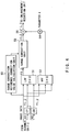
- FIG. 1 shows the internal structure of the image processing unit 37 serving as the image processing apparatus.
- the image processing unit 37 includes a low pass filter (to be called LPF hereinafter) 51 for suppressing moire or the like, of image data read by the scanner unit 1, a range correction unit 52 for correcting the irregularity of the CCD sensor 5, a high pass filter (to be called HPF hereinafter) 53, connected in parallel with the LPF 51, for emphasizing an edge or the like, of a character of the image read by the scanner unit 1, a multiplier for multiplying image data from the range correction unit 52, with a parameter K, which will be described later, an adder 55 for adding image data from the multiplier 54 to image data from the range correction unit 52, an enlargement/contraction unit 56 for subjecting the image data from the adder 55 to an enlargement or contraction process, and ⁇ -correction unit 57 for performing various types of ⁇ -corrections on the image data, and an error diffusion processing unit 58 for subjecting image data from the ⁇ -correction unit 57 to an error diffusion process.
- LPF low pass filter
- HPF high
- FIG. 4 shows an example of the circuit for performing the process of the LPF 51 and HPF 52 for the mask size (3 ⁇ 3) of the structure of the image processing unit 37 shown in FIG. 1. It should be noted that all of the data handled in this case are of 8-bit.
- the range correction unit 52 is connected to a range correction reference correction value calculating unit 60 for calculating out a range correction reference value from the image data from the scanner 1.
- image data input from the scanner 2 is temporarily taken in the line buffers 61 and 62.
- the result of the process by the LPF 51 is further subjected to the range correction process by the range correction unit 52 for the purpose of correcting the contrast of the image, and let us suppose the value of this process is r (i,j).
- the process by the HPF 53 is carried out in a manner similar to that of the LPF 51 as follows. That is, of the image data taken in by the line buffers 61 and 62, the values of the pixels of a local region of (3 ⁇ 3), that is, f(i-1, j-1), f(i, j-1), f(i+1, j-1), f(i-1, j), f(i, j), f(i+1, j), f(i-1, j+1), f(i, j+1) and f(i+1, j+1), are multiplied with coefficients Ha, Hb, Hc and Hd.
- h(i, j) Ha*f(i, j) + Hb*[f(i, j-1) + f(i, j+1)] + Hc*[f(i-1, j) + f(i+1, j)] + Hd*[f(i-1, j-1) + f(i+1, j-1) + f(i-1, j+1) + f(i+1, j+1)].
- the coefficients Ha, Hb, Hc and Hd of the HPF 53 are arranged as can be seen in FIG. 7. Further, the intensity of emphasizing the edge can be changed by multiplying the result of the process by the HPF 53 with the parameter K. In other words, as the value of the coefficient is higher, the degree of the emphasizing the edge becomes higher, and therefore the optimal value can be set in accordance with the MTF characteristics and the like, of the scanner unit 2.
- the filtering process of pixels having a mask size of (3 ⁇ 3) can be realized by only 2 lines of buffers.
- the result of the processing of an input image by the LPF 51, or by the range correction unit 52 is then subjected to the process by the HPF 53, whereas in the present invention, an input image is subjected directly to the process by the HPF 53, and therefore the degree of the emphasis of the edge is made stronger as compared to the conventional technique.
- FIG. 8 shows the results of the evaluation of an image in the case where the value of the parameter K is varied.
- a simulation test proved that when the K value is decreased to about 0.6, an image of a quality as high as that of the conventional technique could be obtained.
- the variation of the image is slightly large with respect to the variation of the value of the parameter K, and therefore it is necessary to set the accuracy of the parameter K more finely than in the conventional case.
- K 0.6
- the preferable value may vary slightly depending upon coefficients selected for the LPF 51 and the HPF 53.
- the edge is emphasized more than that of the above-described embodiment, and therefore the optimal value for the parameter K becomes a lower one.
- an optimal value which corresponds to the coefficients selected for the LPF 51 and the HPF 53 must be selected.
- the arrangement of the coefficients is not limited to that discussed in the above embodiment, and it is possible that all the coefficient values and it is possible that all the coefficient values within a mask size are changed.
- the LPF process and the HPF process for an image input from the scanner can be carried out in parallel, and therefore the number of line memories can be reduced.
- the present invention provides an image forming apparatus capable of reducing the number of line buffers used for the process with a mask size of (n ⁇ n) in the filtering process of the image processing device.
Landscapes
- Engineering & Computer Science (AREA)
- Multimedia (AREA)
- Signal Processing (AREA)
- Image Processing (AREA)
- Facsimiles In General (AREA)
- Facsimile Image Signal Circuits (AREA)
Applications Claiming Priority (2)
| Application Number | Priority Date | Filing Date | Title |
|---|---|---|---|
| JP66424/96 | 1996-03-22 | ||
| JP8066424A JPH09261481A (ja) | 1996-03-22 | 1996-03-22 | 画像形成装置 |
Publications (2)
| Publication Number | Publication Date |
|---|---|
| EP0797347A2 true EP0797347A2 (de) | 1997-09-24 |
| EP0797347A3 EP0797347A3 (de) | 1998-02-18 |
Family
ID=13315404
Family Applications (1)
| Application Number | Title | Priority Date | Filing Date |
|---|---|---|---|
| EP97103893A Withdrawn EP0797347A3 (de) | 1996-03-22 | 1997-03-07 | Bildaufzeichnungsgerät mit einer Bildverarbeitungseinheit mit mehreren parallel angeordneten Filtern |
Country Status (3)
| Country | Link |
|---|---|
| US (1) | US5912744A (de) |
| EP (1) | EP0797347A3 (de) |
| JP (1) | JPH09261481A (de) |
Families Citing this family (14)
| Publication number | Priority date | Publication date | Assignee | Title |
|---|---|---|---|---|
| US6047091A (en) * | 1998-04-01 | 2000-04-04 | Hewlett-Packard Company | Low latency architecture for spatial filtration |
| US6346970B1 (en) * | 1998-08-12 | 2002-02-12 | Focus Enhancements, Inc. | Two-dimensional adjustable flicker filter |
| KR100296596B1 (ko) * | 1999-07-14 | 2001-07-12 | 윤종용 | 4방향 일차원 고역 통과 필터링에 의한 윤곽선 강조 방법 |
| EP1246474A1 (de) * | 2001-03-27 | 2002-10-02 | Koninklijke Philips Electronics N.V. | Bildaufnahmevorrichtung und dazu passender Bildprozessor |
| KR100632679B1 (ko) | 2005-03-09 | 2006-10-12 | 엘지전자 주식회사 | 디지털 디스플레이 디바이스의 영상처리장치 |
| CN100338936C (zh) * | 2005-04-27 | 2007-09-19 | 北京北大方正电子有限公司 | 一种基于双反馈的误差扩散调频挂网方法 |
| JP4832031B2 (ja) * | 2005-09-08 | 2011-12-07 | オリンパスイメージング株式会社 | 画像処理方法及び画像処理装置 |
| US7876973B2 (en) * | 2006-01-12 | 2011-01-25 | Integrity Applications Incorporated | Edge ringing artifact suppression methods and apparatuses |
| US7916352B2 (en) * | 2006-06-30 | 2011-03-29 | Canon Kabushiki Kaisha | Image processing apparatus, image processing method, program, and recording medium |
| EP2206334A2 (de) * | 2007-09-28 | 2010-07-14 | OCE-Technologies B.V. | Verfahren, vorrichtung und computerprogramm zur adaptiven kompensation eines mtf |
| JP4933418B2 (ja) * | 2007-12-21 | 2012-05-16 | キヤノン株式会社 | 画像読取装置、マルチファンクションプリンタ装置、及び画像処理方法 |
| US8243351B2 (en) * | 2007-12-21 | 2012-08-14 | Canon Kabushiki Kaisha | Image reading apparatus, multifunction printer apparatus, and image processing method |
| JP4989444B2 (ja) * | 2007-12-21 | 2012-08-01 | キヤノン株式会社 | 画像読取装置、マルチファンクションプリンタ装置、及び画像処理方法 |
| JP6730916B2 (ja) * | 2016-11-30 | 2020-07-29 | 日本放送協会 | コントラスト補正装置及びプログラム |
Family Cites Families (13)
| Publication number | Priority date | Publication date | Assignee | Title |
|---|---|---|---|---|
| JPS5814270A (ja) * | 1981-07-17 | 1983-01-27 | Fuji Photo Film Co Ltd | 画像走査記録方法 |
| US4499493A (en) * | 1983-02-22 | 1985-02-12 | The Board Of Trustees Of The Leland Stanford Junior University | Multiple measurement noise reducing system using artifact edge identification and selective signal processing |
| JPS61230571A (ja) * | 1985-04-05 | 1986-10-14 | Dainippon Screen Mfg Co Ltd | 画像走査装置 |
| JP2589298B2 (ja) * | 1987-01-28 | 1997-03-12 | キヤノン株式会社 | 符号化画像データの復号化装置 |
| JPH0286266A (ja) * | 1988-09-21 | 1990-03-27 | Fuji Xerox Co Ltd | 画像読取装置 |
| JPH0372778A (ja) * | 1989-08-11 | 1991-03-27 | Fuji Xerox Co Ltd | 画像処理装置の領域識別方式 |
| JP2993014B2 (ja) * | 1989-08-30 | 1999-12-20 | 富士ゼロックス株式会社 | 画像処理装置の画質制御方式 |
| ES2089393T3 (es) * | 1991-03-27 | 1996-10-01 | Canon Kk | Aparato para el proceso de imagenes. |
| KR100206267B1 (ko) * | 1991-08-20 | 1999-07-01 | 윤종용 | 화상처리장치의 화상데이타 경계성분 강조회로 |
| US5273040A (en) * | 1991-11-14 | 1993-12-28 | Picker International, Inc. | Measurement of vetricle volumes with cardiac MRI |
| US5392365A (en) * | 1991-12-23 | 1995-02-21 | Eastman Kodak Company | Apparatus for detecting text edges in digital image processing |
| US5374995A (en) * | 1993-03-22 | 1994-12-20 | Eastman Kodak Company | Method and apparatus for enhancing sharpness of a sequence of images subject to continuous zoom |
| JP3233536B2 (ja) * | 1994-09-16 | 2001-11-26 | 株式会社東芝 | 画像形成装置 |
-
1996
- 1996-03-22 JP JP8066424A patent/JPH09261481A/ja active Pending
-
1997
- 1997-03-07 EP EP97103893A patent/EP0797347A3/de not_active Withdrawn
- 1997-03-11 US US08/815,113 patent/US5912744A/en not_active Expired - Fee Related
Also Published As
| Publication number | Publication date |
|---|---|
| US5912744A (en) | 1999-06-15 |
| JPH09261481A (ja) | 1997-10-03 |
| EP0797347A3 (de) | 1998-02-18 |
Similar Documents
| Publication | Publication Date | Title |
|---|---|---|
| JP3733446B2 (ja) | デジタル複写機 | |
| US5912744A (en) | Image forming apparatus having image processing unit containing a plurality of filters arranged in parallel to each other | |
| JP3519257B2 (ja) | 画像形成装置 | |
| US6271933B1 (en) | Image reading apparatus | |
| US7315399B2 (en) | Image forming apparatus and image forming method | |
| EP0420152B1 (de) | Verfahren und Vorrichtung zur Beseitigung von Falschbildern | |
| US4905096A (en) | Image reading arrangement | |
| JPH08265576A (ja) | 情報処理装置 | |
| JPH10108018A (ja) | 画像処理装置及び画像処理方法、並びに画像形成装置 | |
| JP2001268355A (ja) | 画像読取装置 | |
| US7120294B2 (en) | Image forming apparatus and image forming method | |
| JP2001045245A (ja) | 画像読取装置 | |
| JPH08289132A (ja) | 画像処理装置 | |
| JPH10200710A (ja) | 画像処理装置 | |
| JPH1098612A (ja) | 画像処理装置と画像処理方法と画像形成装置 | |
| JP2592824B2 (ja) | 画信号処理装置 | |
| JP3836970B2 (ja) | 画像形成装置 | |
| JP3756207B2 (ja) | 画像形成装置 | |
| JP2945022B2 (ja) | 画像処理装置 | |
| JPH0846781A (ja) | 画像形成装置 | |
| JP3124839B2 (ja) | 画像形成装置 | |
| JPH08265562A (ja) | 画像変倍装置 | |
| JPH0229072A (ja) | デジタル画像処理装置の画像補正装置 | |
| JP3490845B2 (ja) | デジタル複合機のγ補正装置およびデジタル複合機 | |
| CN1163424A (zh) | 图象形成设备 |
Legal Events
| Date | Code | Title | Description |
|---|---|---|---|
| PUAI | Public reference made under article 153(3) epc to a published international application that has entered the european phase |
Free format text: ORIGINAL CODE: 0009012 |
|
| 17P | Request for examination filed |
Effective date: 19970307 |
|
| AK | Designated contracting states |
Kind code of ref document: A2 Designated state(s): DE FR GB |
|
| PUAL | Search report despatched |
Free format text: ORIGINAL CODE: 0009013 |
|
| AK | Designated contracting states |
Kind code of ref document: A3 Designated state(s): DE FR GB |
|
| STAA | Information on the status of an ep patent application or granted ep patent |
Free format text: STATUS: THE APPLICATION HAS BEEN WITHDRAWN |
|
| 18W | Application withdrawn |
Withdrawal date: 19980619 |