EP0797520B1 - Hydraulische kraftfahrzeugbremsanlage - Google Patents
Hydraulische kraftfahrzeugbremsanlage Download PDFInfo
- Publication number
- EP0797520B1 EP0797520B1 EP95942701A EP95942701A EP0797520B1 EP 0797520 B1 EP0797520 B1 EP 0797520B1 EP 95942701 A EP95942701 A EP 95942701A EP 95942701 A EP95942701 A EP 95942701A EP 0797520 B1 EP0797520 B1 EP 0797520B1
- Authority
- EP
- European Patent Office
- Prior art keywords
- pressure
- pump
- brake
- cylinder
- hydraulic
- Prior art date
- Legal status (The legal status is an assumption and is not a legal conclusion. Google has not performed a legal analysis and makes no representation as to the accuracy of the status listed.)
- Expired - Lifetime
Links
- 239000012530 fluid Substances 0.000 claims description 7
- 238000011144 upstream manufacturing Methods 0.000 claims description 2
- 230000004913 activation Effects 0.000 description 2
- 230000000903 blocking effect Effects 0.000 description 1
- 230000005281 excited state Effects 0.000 description 1
- 238000009434 installation Methods 0.000 description 1
- 238000000926 separation method Methods 0.000 description 1
- 230000003068 static effect Effects 0.000 description 1
Images
Classifications
-
- B—PERFORMING OPERATIONS; TRANSPORTING
- B60—VEHICLES IN GENERAL
- B60T—VEHICLE BRAKE CONTROL SYSTEMS OR PARTS THEREOF; BRAKE CONTROL SYSTEMS OR PARTS THEREOF, IN GENERAL; ARRANGEMENT OF BRAKING ELEMENTS ON VEHICLES IN GENERAL; PORTABLE DEVICES FOR PREVENTING UNWANTED MOVEMENT OF VEHICLES; VEHICLE MODIFICATIONS TO FACILITATE COOLING OF BRAKES
- B60T17/00—Component parts, details, or accessories of power brake systems not covered by groups B60T8/00, B60T13/00 or B60T15/00, or presenting other characteristic features
- B60T17/06—Applications or arrangements of reservoirs
-
- B—PERFORMING OPERATIONS; TRANSPORTING
- B60—VEHICLES IN GENERAL
- B60T—VEHICLE BRAKE CONTROL SYSTEMS OR PARTS THEREOF; BRAKE CONTROL SYSTEMS OR PARTS THEREOF, IN GENERAL; ARRANGEMENT OF BRAKING ELEMENTS ON VEHICLES IN GENERAL; PORTABLE DEVICES FOR PREVENTING UNWANTED MOVEMENT OF VEHICLES; VEHICLE MODIFICATIONS TO FACILITATE COOLING OF BRAKES
- B60T13/00—Transmitting braking action from initiating means to ultimate brake actuator with power assistance or drive; Brake systems incorporating such transmitting means, e.g. air-pressure brake systems
- B60T13/10—Transmitting braking action from initiating means to ultimate brake actuator with power assistance or drive; Brake systems incorporating such transmitting means, e.g. air-pressure brake systems with fluid assistance, drive, or release
- B60T13/12—Transmitting braking action from initiating means to ultimate brake actuator with power assistance or drive; Brake systems incorporating such transmitting means, e.g. air-pressure brake systems with fluid assistance, drive, or release the fluid being liquid
- B60T13/16—Transmitting braking action from initiating means to ultimate brake actuator with power assistance or drive; Brake systems incorporating such transmitting means, e.g. air-pressure brake systems with fluid assistance, drive, or release the fluid being liquid using pumps directly, i.e. without interposition of accumulators or reservoirs
- B60T13/168—Arrangements for pressure supply
-
- B—PERFORMING OPERATIONS; TRANSPORTING
- B60—VEHICLES IN GENERAL
- B60T—VEHICLE BRAKE CONTROL SYSTEMS OR PARTS THEREOF; BRAKE CONTROL SYSTEMS OR PARTS THEREOF, IN GENERAL; ARRANGEMENT OF BRAKING ELEMENTS ON VEHICLES IN GENERAL; PORTABLE DEVICES FOR PREVENTING UNWANTED MOVEMENT OF VEHICLES; VEHICLE MODIFICATIONS TO FACILITATE COOLING OF BRAKES
- B60T8/00—Arrangements for adjusting wheel-braking force to meet varying vehicular or ground-surface conditions, e.g. limiting or varying distribution of braking force
- B60T8/32—Arrangements for adjusting wheel-braking force to meet varying vehicular or ground-surface conditions, e.g. limiting or varying distribution of braking force responsive to a speed condition, e.g. acceleration or deceleration
- B60T8/34—Arrangements for adjusting wheel-braking force to meet varying vehicular or ground-surface conditions, e.g. limiting or varying distribution of braking force responsive to a speed condition, e.g. acceleration or deceleration having a fluid pressure regulator responsive to a speed condition
- B60T8/48—Arrangements for adjusting wheel-braking force to meet varying vehicular or ground-surface conditions, e.g. limiting or varying distribution of braking force responsive to a speed condition, e.g. acceleration or deceleration having a fluid pressure regulator responsive to a speed condition connecting the brake actuator to an alternative or additional source of fluid pressure, e.g. traction control systems
- B60T8/4809—Traction control, stability control, using both the wheel brakes and other automatic braking systems
- B60T8/4827—Traction control, stability control, using both the wheel brakes and other automatic braking systems in hydraulic brake systems
- B60T8/4845—Traction control, stability control, using both the wheel brakes and other automatic braking systems in hydraulic brake systems using a booster or a master cylinder for traction control
-
- B—PERFORMING OPERATIONS; TRANSPORTING
- B60—VEHICLES IN GENERAL
- B60T—VEHICLE BRAKE CONTROL SYSTEMS OR PARTS THEREOF; BRAKE CONTROL SYSTEMS OR PARTS THEREOF, IN GENERAL; ARRANGEMENT OF BRAKING ELEMENTS ON VEHICLES IN GENERAL; PORTABLE DEVICES FOR PREVENTING UNWANTED MOVEMENT OF VEHICLES; VEHICLE MODIFICATIONS TO FACILITATE COOLING OF BRAKES
- B60T8/00—Arrangements for adjusting wheel-braking force to meet varying vehicular or ground-surface conditions, e.g. limiting or varying distribution of braking force
- B60T8/32—Arrangements for adjusting wheel-braking force to meet varying vehicular or ground-surface conditions, e.g. limiting or varying distribution of braking force responsive to a speed condition, e.g. acceleration or deceleration
- B60T8/34—Arrangements for adjusting wheel-braking force to meet varying vehicular or ground-surface conditions, e.g. limiting or varying distribution of braking force responsive to a speed condition, e.g. acceleration or deceleration having a fluid pressure regulator responsive to a speed condition
- B60T8/48—Arrangements for adjusting wheel-braking force to meet varying vehicular or ground-surface conditions, e.g. limiting or varying distribution of braking force responsive to a speed condition, e.g. acceleration or deceleration having a fluid pressure regulator responsive to a speed condition connecting the brake actuator to an alternative or additional source of fluid pressure, e.g. traction control systems
- B60T8/4809—Traction control, stability control, using both the wheel brakes and other automatic braking systems
- B60T8/4827—Traction control, stability control, using both the wheel brakes and other automatic braking systems in hydraulic brake systems
- B60T8/4845—Traction control, stability control, using both the wheel brakes and other automatic braking systems in hydraulic brake systems using a booster or a master cylinder for traction control
- B60T8/4854—Traction control, stability control, using both the wheel brakes and other automatic braking systems in hydraulic brake systems using a booster or a master cylinder for traction control pneumatic boosters
-
- B—PERFORMING OPERATIONS; TRANSPORTING
- B60—VEHICLES IN GENERAL
- B60T—VEHICLE BRAKE CONTROL SYSTEMS OR PARTS THEREOF; BRAKE CONTROL SYSTEMS OR PARTS THEREOF, IN GENERAL; ARRANGEMENT OF BRAKING ELEMENTS ON VEHICLES IN GENERAL; PORTABLE DEVICES FOR PREVENTING UNWANTED MOVEMENT OF VEHICLES; VEHICLE MODIFICATIONS TO FACILITATE COOLING OF BRAKES
- B60T8/00—Arrangements for adjusting wheel-braking force to meet varying vehicular or ground-surface conditions, e.g. limiting or varying distribution of braking force
- B60T8/32—Arrangements for adjusting wheel-braking force to meet varying vehicular or ground-surface conditions, e.g. limiting or varying distribution of braking force responsive to a speed condition, e.g. acceleration or deceleration
- B60T8/34—Arrangements for adjusting wheel-braking force to meet varying vehicular or ground-surface conditions, e.g. limiting or varying distribution of braking force responsive to a speed condition, e.g. acceleration or deceleration having a fluid pressure regulator responsive to a speed condition
- B60T8/48—Arrangements for adjusting wheel-braking force to meet varying vehicular or ground-surface conditions, e.g. limiting or varying distribution of braking force responsive to a speed condition, e.g. acceleration or deceleration having a fluid pressure regulator responsive to a speed condition connecting the brake actuator to an alternative or additional source of fluid pressure, e.g. traction control systems
- B60T8/4809—Traction control, stability control, using both the wheel brakes and other automatic braking systems
- B60T8/4827—Traction control, stability control, using both the wheel brakes and other automatic braking systems in hydraulic brake systems
- B60T8/4863—Traction control, stability control, using both the wheel brakes and other automatic braking systems in hydraulic brake systems closed systems
- B60T8/4872—Traction control, stability control, using both the wheel brakes and other automatic braking systems in hydraulic brake systems closed systems pump-back systems
- B60T8/4881—Traction control, stability control, using both the wheel brakes and other automatic braking systems in hydraulic brake systems closed systems pump-back systems having priming means
-
- B—PERFORMING OPERATIONS; TRANSPORTING
- B60—VEHICLES IN GENERAL
- B60T—VEHICLE BRAKE CONTROL SYSTEMS OR PARTS THEREOF; BRAKE CONTROL SYSTEMS OR PARTS THEREOF, IN GENERAL; ARRANGEMENT OF BRAKING ELEMENTS ON VEHICLES IN GENERAL; PORTABLE DEVICES FOR PREVENTING UNWANTED MOVEMENT OF VEHICLES; VEHICLE MODIFICATIONS TO FACILITATE COOLING OF BRAKES
- B60T8/00—Arrangements for adjusting wheel-braking force to meet varying vehicular or ground-surface conditions, e.g. limiting or varying distribution of braking force
- B60T8/32—Arrangements for adjusting wheel-braking force to meet varying vehicular or ground-surface conditions, e.g. limiting or varying distribution of braking force responsive to a speed condition, e.g. acceleration or deceleration
- B60T8/34—Arrangements for adjusting wheel-braking force to meet varying vehicular or ground-surface conditions, e.g. limiting or varying distribution of braking force responsive to a speed condition, e.g. acceleration or deceleration having a fluid pressure regulator responsive to a speed condition
- B60T8/48—Arrangements for adjusting wheel-braking force to meet varying vehicular or ground-surface conditions, e.g. limiting or varying distribution of braking force responsive to a speed condition, e.g. acceleration or deceleration having a fluid pressure regulator responsive to a speed condition connecting the brake actuator to an alternative or additional source of fluid pressure, e.g. traction control systems
- B60T8/4809—Traction control, stability control, using both the wheel brakes and other automatic braking systems
- B60T8/4827—Traction control, stability control, using both the wheel brakes and other automatic braking systems in hydraulic brake systems
- B60T8/489—Traction control, stability control, using both the wheel brakes and other automatic braking systems in hydraulic brake systems using separate traction control modulators
Definitions
- the invention relates to a hydraulic motor vehicle brake system for driving stability control and / or traction control with one based on the return feed principle anti-lock braking system (ABS), one by one Brake pedal operated brake pressure sensor, which consists of a Brake booster and one the brake booster downstream, with a pressure medium reservoir in Connected two-circuit master brake cylinder exists, according to the preamble of claim 1.
- ABS return feed principle anti-lock braking system
- Such a hydraulic motor vehicle brake system is e.g. known from DE-PS 43 29 139, in which as Brake pressure control unit is a tandem master cylinder static master cylinder with the brake circuits individually assigned pressure outputs is provided.
- the Driving stability control device works on the principle through electronically controlled, automatic activation one or more wheel brakes the longitudinal and side slip of vehicle wheels within with dynamic Stability of the vehicle overall tolerable limits hold.
- this individually assigned precharge cylinder provided each have a piston that has an outlet pressure chamber, the via an electrically controllable precharge control valve the suction side of the return pump of the respective brake circuit is connectable to a drive pressure chamber the pressure outlet of the precharge pump is connected, delimited pressure-tight and two at an axial distance from each other arranged flanges, between which there is one with each one of the pressure outputs of the braking device in constantly communicating connection held trailing area extends, the piston of the respective precharging cylinder is provided with a mechanically actuated valve that also performs the function of a check valve that one connecting the trailing chamber with the outlet pressure chamber Flow channel of the piston blocks as long as the pressure in Output pressure space of the respective precharge cylinder is larger than in the wake space and this flow channel clears, when the master cylinder output pressure prevailing in the after-space is greater than the pressure in the outlet pressure chamber of the precharge cylinder.
- the suction sides of the two return pumps are on the Main brake line of the respective brake circuit via one each Check valve connected by relatively higher Pressure in the return line of the respective brake circuit as on the suction side of his return pump in the opening direction is applied and otherwise blocking.
- the two Pre-charge cylinders have a common one, at the pressure outlet the precharge pump connected drive pressure chamber, the by controlling a normally open solenoid valve from the pressure medium reservoir of the brake system is separable.
- the known brake system compared to a vehicle equipped with an anti-lock device and is equipped with a traction control system that an automatic activation of only the wheel brakes of the driven vehicle wheels allows, essential more complex and correspondingly more expensive. It is added that in such a brake system because of additional precharging cylinder also additional hydraulic Chambers are present, from which gas bubbles that form strong thermal load on the wheel brakes, can only escape with difficulty, which is especially true when the two precharge cylinders become symmetrical Unit are summarized and therefore the one reasonably good ventability of both precharge cylinders cheapest arrangement of the same in the sense of a best possible compromise can be made.
- the hydraulic pre-charge pump can be a second pressure medium reservoir can be assigned, wherein the connection between the suction side of the precharge pump and the second pressure medium reservoir can be shut off.
- the connection mentioned is preferably shut off by means of an electromagnetically operated 2/2-way valve, being between the second pressure medium reservoir and the pressure side of the precharge pump Throttle is switched.
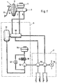
- the invention shown in the drawing Brake system has two brake circuits I and II, their Structure is completely identical, so the following Description of one brake circuit as well on the other applies.
- the brake system shown consists essentially from a brake pressure sensor 1, to which no closer designated hydraulic lines wheel brake cylinder are connectable, one between the brake pressure sensor 1 and the wheel brakes switched hydraulic unit 2, and one not shown electronic controller with associated Sensors.
- the assignment of the wheel brake cylinders to the individual brake circuits I, II is made such that the first wheel brake cylinder either a wheel one Vehicle axle and the other wheel brake cylinder diagonally opposite wheel assigned to the other vehicle axle is (diagonal division of the brake circuits) or both Wheel brake cylinders are assigned to the same vehicle axle (Black and white division of the brake circuits).
- actuatable pressure transmitter 1 consists of a pneumatic Brake booster 5, which is a master brake cylinder, preferably a tandem master cylinder 3 is connected, the Pressure rooms can be connected to a pressure medium reservoir 4 are.
- An actuating rod 34 is on the brake pedal 33 coupled, the actuation of a not shown Control valve enabled by the vehicle driver, the Development of a pneumatic differential pressure in the housing of the Vacuum brake booster 5 controls.
- a hydraulic unit 2 has a motor-pump unit, that from a driven by an electric motor 54 hydraulic return pump 52 exists.
- the return pump 52 the pressure medium below to provide a higher pressure, or a Reaching the wheel brakes is one Auxiliary pressure source 6 is provided.
- Motor vehicle brake system is the auxiliary pressure source 6 between the master brake cylinder 3 and the hydraulic unit 2 are arranged and consists of an auxiliary pressure pump 53, one to the Pressure side of the auxiliary pressure pump 53 connected hydraulic drive 59 and one from drive 59 actuatable, two-circuit precharging cylinder 58.
- Die Special feature of this version is that the im Hydraulic unit 2 integrated return pump 52 and the Auxiliary pressure pump 53 have a common drive, the in the example shown by an electric motor 54 is formed.
- the auxiliary pressure pump 53 a second pressure medium reservoir 55 assigned, whose connection with the suction side of the Auxiliary pressure pump 53 by means of a preferably electromagnetic actuatable 2/2-way valve 56 can be shut off can.
- the second pressure medium reservoir 55 can omitted if a direct connection with a large cross-section between the 2/2-way or loading valve 56 and the first pressure medium reservoir 4 is produced.
- Auxiliary pressure pump 53 delivers, from the second pressure medium reservoir 55 sucking in pressure medium, a pressure medium flow, with which the hydraulic drive 59 is applied, so that in the precharge cylinder 58 Precharge pressure is built up.
- the 2/2-way or charging valve 56 is closed and that in the connecting line between the auxiliary pressure pump 53 and the hydraulic drive 59 prevailing Auxiliary pressure is via a on the pressure side of the auxiliary pressure pump 53 connected throttle 57 removed.
- the Auxiliary pressure pump 53 is designed as a vacuum pump, which then with a vacuum drive upstream of the precharge cylinder 58 cooperates.
Landscapes
- Engineering & Computer Science (AREA)
- Physics & Mathematics (AREA)
- Fluid Mechanics (AREA)
- Transportation (AREA)
- Mechanical Engineering (AREA)
- Regulating Braking Force (AREA)
- Braking Systems And Boosters (AREA)
Description
- Fig. 1
- eine blockiergeschützte Kraftfahrzeugbremsanlage nach der Erfindung.
- 1
- Bremsdruckgeber
- 2
- Hydraulikaggregat
- 3
- Hauptbremszylinder
- 4
- Druckmittelvorratsbehälter
- 5
- Bremskraftverstärker
- 6
- Hilfsdruckquelle
- 33
- Bremspedal
- 34
- Betätigungsstange
- 52
- Rückförderpumpe
- 53
- Hilfsdruckpumpe
- 54
- Elektromotor
- 55
- Druckmittelvorratsbehälter
- 56
- 2/2-Wegeventil
- 57
- Drossel
- 58
- Vorladezylinder
- 59
- Antrieb
Claims (3)
- Hydraulische Kraftfahrzeugbremsanlage zur Fahrstabilitäts- und/ oder Antriebsschlupfregelung, mit einem nach dem Rückförderprinzip arbeitenden Blockierschutzsystem, einem von einem Bremspedal (33) betätigbaren Bremsdruckgeber (1), der aus einem Bremskraftverstärker (5) sowie einem dem Bremskraftverstärker (5) nachgeschalteten, mit einem Druckmittelvorratsbehälter (4) in Verbindung stehenden zweikreisigen Hauptbremszylinder (3) besteht, an dessen Druckräume über ein eine Rückförderpumpe (52) aufweisendes Hydraulikaggregat (2) den einzelnen Fahrzeugrädern zugeordnete Radbremsen angeschlossen sind, sowie mit einer Hilfsdruckquelle (6), die wirkungsmäßig zwischen dem Hauptbremszylinder (3) und dem Hydraulikaggregat (2) angeordnet ist, durch eine Hilfsdruckpumpe (53) sowie mindestens einen Vorladezylinder (58) gebildet ist und deren Druckmittelstrom wahlweise den Radbremsen oder der Saugseite der Rückförderpumpe (52) zuführbar ist, dadurch gekennzeichnet, daß die Rückförderpumpe (52) sowie die Hilfsdruckpumpe (53) einen gemeinsamen Antrieb (54) aufweisen.
- Hydraulische Kraftfahrzeugbremsanlage nach Anspruch 1 dadurch gekennzeichnet, daß der Hilfsdruckpumpe (53) ein zweiter Druckmittelvorratsbehälter (55) zugeordnet ist und daß die Verbindung zwischen ihrer Saugseite und dem zweiten Druckmittelvorratsbehälter (55) absperrbar ist.
- Hydraulische Kraftfahrzeugbremsanlage nach Anspruch 2 dadurch gekennzeichnet, daß der Hilfsdruckpumpe (53) ein elektromagnetisch betätigbares 2/2-Wege-ventil (56) vorgeschaltet ist, wobei zwischen dem zweiten Druckmittelvorratsbehälter (55) und der Druckseite der Hilfsdruckpumpe (53) eine Drossel (57) geschaltet ist.
Priority Applications (1)
| Application Number | Priority Date | Filing Date | Title |
|---|---|---|---|
| EP99107537A EP0930208B1 (de) | 1994-12-24 | 1995-12-19 | Hydraulische Kraftfahrzeugbremsanlage |
Applications Claiming Priority (3)
| Application Number | Priority Date | Filing Date | Title |
|---|---|---|---|
| DE4446525A DE4446525A1 (de) | 1994-12-24 | 1994-12-24 | Hydraulische Kraftfahrzeugbremsanlage |
| DE4446525 | 1994-12-24 | ||
| PCT/EP1995/005028 WO1996020102A1 (de) | 1994-12-24 | 1995-12-19 | Hydraulische kraftfahrzeugbremsanlage |
Related Child Applications (2)
| Application Number | Title | Priority Date | Filing Date |
|---|---|---|---|
| EP99107537A Division EP0930208B1 (de) | 1994-12-24 | 1995-12-19 | Hydraulische Kraftfahrzeugbremsanlage |
| EP99101641 Division | 1999-02-04 |
Publications (2)
| Publication Number | Publication Date |
|---|---|
| EP0797520A2 EP0797520A2 (de) | 1997-10-01 |
| EP0797520B1 true EP0797520B1 (de) | 1999-12-01 |
Family
ID=6537062
Family Applications (2)
| Application Number | Title | Priority Date | Filing Date |
|---|---|---|---|
| EP99107537A Expired - Lifetime EP0930208B1 (de) | 1994-12-24 | 1995-12-19 | Hydraulische Kraftfahrzeugbremsanlage |
| EP95942701A Expired - Lifetime EP0797520B1 (de) | 1994-12-24 | 1995-12-19 | Hydraulische kraftfahrzeugbremsanlage |
Family Applications Before (1)
| Application Number | Title | Priority Date | Filing Date |
|---|---|---|---|
| EP99107537A Expired - Lifetime EP0930208B1 (de) | 1994-12-24 | 1995-12-19 | Hydraulische Kraftfahrzeugbremsanlage |
Country Status (5)
| Country | Link |
|---|---|
| EP (2) | EP0930208B1 (de) |
| JP (1) | JP2002514985A (de) |
| DE (3) | DE4446525A1 (de) |
| ES (1) | ES2141976T3 (de) |
| WO (1) | WO1996020102A1 (de) |
Families Citing this family (26)
| Publication number | Priority date | Publication date | Assignee | Title |
|---|---|---|---|---|
| DE19618402A1 (de) * | 1996-05-08 | 1997-11-13 | Bosch Gmbh Robert | Hydraulische Fahrzeugbremsanlage |
| JP2000513299A (ja) * | 1996-07-01 | 2000-10-10 | アイティーティー・マニュファクチャリング・エンタープライジズ・インコーポレーテッド | 液圧式ブレーキシステム |
| DE19632130A1 (de) * | 1996-07-01 | 1998-01-08 | Teves Gmbh Alfred | Hydraulische Bremsanlage |
| DE19638920A1 (de) | 1996-09-23 | 1998-03-26 | Teves Gmbh Alfred | Hydraulische Bremsanlage mit Bremskraftverstärkung |
| DE19639560A1 (de) * | 1996-09-26 | 1998-04-02 | Bosch Gmbh Robert | Hydraulische Fahrzeugbremsanlage |
| DE19700410A1 (de) * | 1997-01-09 | 1998-07-16 | Teves Gmbh Alfred | Hydraulikaggregat |
| DE19703393A1 (de) * | 1997-01-30 | 1998-08-06 | Itt Mfg Enterprises Inc | Schlupfgeregelte Kraftfahrzeugbremsanlage mit druckmittelabhängiger Einschaltung einer Druckmittelhilfsquelle |
| DE19708425A1 (de) * | 1997-03-01 | 1998-09-03 | Itt Mfg Enterprises Inc | Hydraulische Fahrzeugbremsanlage |
| DE19757039A1 (de) * | 1997-12-20 | 1999-06-24 | Itt Mfg Enterprises Inc | Hydraulische Bremsanlage für Kraftfahrzeuge mit einer Bremsschlupfregeleinrichtung |
| DE10011801B4 (de) | 1999-03-17 | 2018-09-13 | Continental Teves Ag & Co. Ohg | System zur Regelung der Fahrstabilität eines Fahrzeugs |
| WO2000055023A1 (de) | 1999-03-17 | 2000-09-21 | Continental Teves Ag & Co. Ohg | Verfahren zum bestimmen von kenngrssöen |
| DE19921478A1 (de) * | 1999-05-08 | 2000-11-09 | Continental Teves Ag & Co Ohg | Hydraulische Bremsanlage |
| DE10059348B4 (de) * | 1999-12-03 | 2016-12-01 | Continental Teves Ag & Co. Ohg | Verfahren zur Ansteuerung einer Bremsvorrichtung in einem Kraftfahrzeug, sowie Bremsvorrichtung |
| JP2001310730A (ja) * | 2000-04-26 | 2001-11-06 | Denso Corp | ポンプ装置及びブレーキ装置 |
| DE10218973A1 (de) * | 2002-04-27 | 2003-11-06 | Continental Teves Ag & Co Ohg | Verfahren zur Steuerung einer hydraulischen Fahrzeugbremsanlage mit aktiver hydraulischer Bremskraftverstärkung und hydraulischer Bremsanlage |
| DE102004049088A1 (de) * | 2004-10-08 | 2006-04-13 | Robert Bosch Gmbh | Fahrzeugbremsanlage mit einem Vorratsbehälter |
| CN100503328C (zh) * | 2006-05-10 | 2009-06-24 | 比亚迪股份有限公司 | 一种电液制动系统 |
| DE102008014462A1 (de) | 2008-03-14 | 2009-09-17 | Robert Bosch Gmbh | Hydraulische Fahrzeugbremsanlage |
| US8801110B2 (en) | 2009-02-13 | 2014-08-12 | Honda Motor Co., Ltd. | Vehicle brake device |
| DE102009010050A1 (de) | 2009-02-21 | 2010-08-26 | Continental Teves Ag & Co. Ohg | Hydraulikaggregat |
| DE102010055044A1 (de) * | 2010-11-08 | 2012-05-10 | Ipgate Ag | Kolben-Zylinder-Vorrichtung, zur Förderung einer Hydraulikflüssigkeit, insbesondere für eine Fahrzeugbremse |
| JP6529006B2 (ja) * | 2015-02-13 | 2019-06-12 | ヴィオニア日信ブレーキシステムジャパン株式会社 | シリンダ装置およびブレーキシステム |
| DE102017221058A1 (de) * | 2017-11-24 | 2019-05-29 | Continental Teves Ag & Co. Ohg | Bremssystem für Kraftfahrzeuge und Betriebsverfahren |
| CN111873971A (zh) * | 2020-07-30 | 2020-11-03 | 重庆长安汽车股份有限公司 | 一种汽车真空助力制动系统 |
| CN113581154A (zh) * | 2021-08-31 | 2021-11-02 | 重庆长安汽车股份有限公司 | 一种消音减振装置、制动真空管路及车辆 |
| DE102023211512A1 (de) * | 2023-11-20 | 2025-05-22 | Robert Bosch Gesellschaft mit beschränkter Haftung | Bremskraftverstärkereinrichtung, Bremssystem und Fahrzeug |
Family Cites Families (42)
| Publication number | Priority date | Publication date | Assignee | Title |
|---|---|---|---|---|
| DE2208936A1 (de) * | 1972-02-25 | 1973-09-06 | Teldix Gmbh | Bremssystem fuer ein fahrzeug |
| US4475336A (en) * | 1981-08-19 | 1984-10-09 | The Bendix Corporation | Braking apparatus for an automotive vehicle |
| DE3337545A1 (de) * | 1983-10-15 | 1985-04-25 | Robert Bosch Gmbh, 7000 Stuttgart | Hydraulische bremsanlage |
| DE3424912A1 (de) * | 1984-07-06 | 1986-01-16 | Alfred Teves Gmbh, 6000 Frankfurt | Elektronisch kontrolliertes bremsbetaetigungssystem |
| US4871215A (en) * | 1984-08-20 | 1989-10-03 | Tokico Ltd. | Vehicle braking system |
| DE3502473A1 (de) * | 1985-01-25 | 1986-07-31 | Alfred Teves Gmbh, 6000 Frankfurt | Hydraulische bremsanlage |
| DE3603697C2 (de) * | 1986-02-06 | 1994-10-20 | Teves Gmbh Alfred | Hydraulische Bremsanlage für Kraftfahrzeuge |
| DE3623736C2 (de) * | 1986-07-14 | 1998-01-29 | Teves Gmbh Alfred | Hydraulische Bremsanlage für Kraftfahrzeuge |
| DE3629776A1 (de) * | 1986-09-02 | 1988-03-10 | Teves Gmbh Alfred | Hydraulische bremsanlage fuer kraftfahrzeuge |
| DE3633687A1 (de) * | 1986-10-03 | 1988-04-14 | Bosch Gmbh Robert | Automatische antriebsschlupfregeleinheit |
| DE3635846C2 (de) * | 1986-10-22 | 1995-08-03 | Teves Gmbh Alfred | Blockiergeschützte Bremsanlage mit Antriebsschlupfregelung |
| GB8719299D0 (en) * | 1987-08-14 | 1987-09-23 | Lucas Ind Plc | Traction control system |
| DE3737466A1 (de) * | 1987-11-05 | 1989-05-18 | Teves Gmbh Alfred | Bremsdruckregelvorrichtung |
| DE3800854A1 (de) * | 1988-01-14 | 1989-07-27 | Bosch Gmbh Robert | Bremsanlage mit antiblockier- und antriebsschlupfregelung |
| DE3803079A1 (de) * | 1988-02-03 | 1989-08-17 | Bosch Gmbh Robert | Elektromechanisch betaetigbarer druckmodulator fuer blockierschutz- und antriebsschlupfregelanlagen |
| DE3803563A1 (de) * | 1988-02-06 | 1989-08-17 | Teves Gmbh Alfred | Hydraulisches motorrad-bremssystem |
| JPH0277350A (ja) * | 1988-09-13 | 1990-03-16 | Akebono Brake Ind Co Ltd | ブレーキ液圧制御装置 |
| DE3832722A1 (de) * | 1988-09-27 | 1990-03-29 | Bosch Gmbh Robert | Bremsanlage |
| DE3923742A1 (de) * | 1989-07-18 | 1991-01-24 | Bosch Gmbh Robert | Hydraulische fahrzeug-bremsanlage |
| JP2784211B2 (ja) * | 1989-07-20 | 1998-08-06 | トキコ株式会社 | トラクション制御方法 |
| DE3924084A1 (de) * | 1989-07-20 | 1991-01-24 | Teves Gmbh Alfred | Hydraulische bremsanlage |
| DE3936180A1 (de) * | 1989-10-31 | 1991-02-21 | Daimler Benz Ag | Antriebs-schlupf-regeleinrichtung |
| US5236257A (en) * | 1990-03-20 | 1993-08-17 | Toyota Jidosha Kabushiki Kaisha | Brake pressure generator having means for controlling pressure independent of operation of brake operating member |
| DE4013159A1 (de) * | 1990-04-25 | 1991-10-31 | Bosch Gmbh Robert | Gehaeuseblock fuer ein hydraulisches bremssystem |
| DE4013835A1 (de) * | 1990-04-30 | 1991-10-31 | Teves Gmbh Alfred | Diagonalbremsanlage mit blockierschutzregelung |
| DE4016561A1 (de) * | 1990-05-23 | 1991-11-28 | Bosch Gmbh Robert | Bremsanlage |
| DE4017872A1 (de) * | 1990-06-02 | 1991-12-05 | Bosch Gmbh Robert | Hydraulische fahrzeugbremsanlage mit antiblockiersystem und antriebsschlupfregelung |
| DE4034114A1 (de) * | 1990-10-26 | 1992-04-30 | Bosch Gmbh Robert | Hydraulische bremsanlage, insbesondere fuer kraftfahrzeuge |
| DE4110851A1 (de) * | 1991-04-04 | 1992-10-08 | Teves Gmbh Alfred | Kraftfahrzeugbremsanlage mit bremsschlupf- und antriebsschlupfabhaengiger regelung des bremsdruckes |
| DE4117546A1 (de) * | 1991-05-29 | 1992-12-03 | Teves Gmbh Alfred | Blockiergeschuetzte kraftfahrzeugbremsanlage |
| DE4123637A1 (de) * | 1991-07-17 | 1993-01-21 | Teves Gmbh Alfred | Blockiergeschuetzte kraftfahrzeugbremsanlage |
| DE4128091C2 (de) * | 1991-08-24 | 1998-02-26 | Teves Gmbh Alfred | Bremsanlage mit Blockierschutz- und Antriebsschlupfregelung |
| US5234263A (en) * | 1992-03-09 | 1993-08-10 | General Motors Corporation | Electric master cylinder traction control |
| DE4208496C1 (de) * | 1992-03-17 | 1993-08-05 | Mercedes-Benz Aktiengesellschaft, 7000 Stuttgart, De | |
| DE4213621A1 (de) * | 1992-04-24 | 1993-10-28 | Teves Gmbh Alfred | Blockiergeschützte hydraulische Bremsanlage |
| DE4213740A1 (de) * | 1992-04-25 | 1993-10-28 | Bosch Gmbh Robert | Verfahren zum Beschleunigen des Bremseneingriffs im Antriebsschlupfregelbetrieb und hydraulische Bremsanlage zur Durchführung des Verfahrens |
| DE4232311C1 (de) * | 1992-09-26 | 1994-02-24 | Bosch Gmbh Robert | Hydraulische Fahrzeugbremsanlage mit Blockierschutzeinrichtung |
| DE4238333C2 (de) * | 1992-11-13 | 2001-10-11 | Continental Teves Ag & Co Ohg | Unterdruckbremskraftverstärker |
| DE4309470C2 (de) * | 1993-03-24 | 2002-09-19 | Bosch Gmbh Robert | Hydraulische Fahrzeugbremsanlage mit Blockierschutzeinrichtung |
| DE4314448A1 (de) * | 1993-05-03 | 1994-11-10 | Teves Gmbh Alfred | Bremsanlage für Kraftfahrzeuge mit elektrischem Antrieb |
| DE4329139C1 (de) * | 1993-08-30 | 1994-07-28 | Daimler Benz Ag | Bremsdruck-Steuereinrichtung |
| DE4329140C1 (de) * | 1993-08-30 | 1994-12-01 | Daimler Benz Ag | Bremsdruck-Steuereinrichtung |
-
1994
- 1994-12-24 DE DE4446525A patent/DE4446525A1/de not_active Withdrawn
-
1995
- 1995-12-19 ES ES95942701T patent/ES2141976T3/es not_active Expired - Lifetime
- 1995-12-19 EP EP99107537A patent/EP0930208B1/de not_active Expired - Lifetime
- 1995-12-19 WO PCT/EP1995/005028 patent/WO1996020102A1/de not_active Ceased
- 1995-12-19 DE DE59511078T patent/DE59511078D1/de not_active Expired - Fee Related
- 1995-12-19 DE DE59507349T patent/DE59507349D1/de not_active Expired - Lifetime
- 1995-12-19 JP JP52018696A patent/JP2002514985A/ja active Pending
- 1995-12-19 EP EP95942701A patent/EP0797520B1/de not_active Expired - Lifetime
Also Published As
| Publication number | Publication date |
|---|---|
| EP0930208A2 (de) | 1999-07-21 |
| DE59507349D1 (de) | 2000-01-05 |
| DE4446525A1 (de) | 1996-06-27 |
| EP0930208A3 (de) | 1999-08-04 |
| DE59511078D1 (de) | 2007-04-05 |
| JP2002514985A (ja) | 2002-05-21 |
| WO1996020102A1 (de) | 1996-07-04 |
| ES2141976T3 (es) | 2000-04-01 |
| EP0797520A2 (de) | 1997-10-01 |
| EP0930208B1 (de) | 2007-02-21 |
Similar Documents
| Publication | Publication Date | Title |
|---|---|---|
| EP0930208B1 (de) | Hydraulische Kraftfahrzeugbremsanlage | |
| EP0853570B1 (de) | Elektronisch regelbares bremsbetätigungssystem | |
| EP0854808B1 (de) | Elektronisch regelbares bremsbetätigungssystem | |
| EP2044337B1 (de) | Elektrohydraulisches regelsystem zur betätigung von einem aktuator in einem kraftfahrzeug | |
| EP0613429B1 (de) | Hydraulische fahrzeugbremsanlage mit blockierschutzeinrichtung | |
| US6135575A (en) | Electronically controllable brake actuating system | |
| DE102017211953A1 (de) | Bremssystem | |
| DE3802133C2 (de) | ||
| DE19542654A1 (de) | Elektronische steuerbare Bremsanlage für Kraftfahrzeuge | |
| DE19626926B4 (de) | Elektronisch regelbares Bremsbetätigungssystem | |
| EP2040967B1 (de) | Verfahren zum bereitstellen von unterdruck einer bremsbetätigungsvorrichtung einer kraftfahrzeugbremsanlage | |
| EP0868335A1 (de) | Fahrzeugbremsanlage mit einer antriebsschlupf- und/oder einer fahrdynamikregeleinrichtung | |
| EP0722397B1 (de) | Bremsanlage für kraftfahrzeuge | |
| DE19716404C1 (de) | Hydraulische Bremsanlage für Kraftfahrzeuge | |
| EP0775618A1 (de) | Hydraulische Fahrzeugbremsanlage mit Radschlupfregeleinrichtung | |
| DE19933483C1 (de) | Druckmittelbetätigte Fahrzeugbremsanlage | |
| DE10319194B3 (de) | Kombinierte hydraulische und elektromechanische Fahrzeugbremsanlage mit einer Bremskraftregeleinrichtung | |
| DE4011329A1 (de) | Hydraulische zweikreisbremsanlage | |
| DE4401995C1 (de) | Bremsdruck-Steuereinrichtung | |
| DE10053993B4 (de) | Hydraulische Bremsanlage und Verfahren zur Bremsdruckerzeugung und -regelung für Fahrzeugbremssystem | |
| DE4021454A1 (de) | Hydraulische bremsanlage | |
| DE4016744A1 (de) | Bremsdruckregelvorrichtung | |
| DE3403237A1 (de) | Bremsanlage fuer kraftfahrzeuge | |
| DE3506853C2 (de) | ||
| EP1334893A2 (de) | Elektrohydraulische Fahrzeugbremsanlage |
Legal Events
| Date | Code | Title | Description |
|---|---|---|---|
| PUAI | Public reference made under article 153(3) epc to a published international application that has entered the european phase |
Free format text: ORIGINAL CODE: 0009012 |
|
| 17P | Request for examination filed |
Effective date: 19970724 |
|
| AK | Designated contracting states |
Kind code of ref document: A2 Designated state(s): DE ES FR GB IT |
|
| 17Q | First examination report despatched |
Effective date: 19971106 |
|
| GRAG | Despatch of communication of intention to grant |
Free format text: ORIGINAL CODE: EPIDOS AGRA |
|
| RAP1 | Party data changed (applicant data changed or rights of an application transferred) |
Owner name: CONTINENTAL TEVES AG & CO. OHG |
|
| GRAG | Despatch of communication of intention to grant |
Free format text: ORIGINAL CODE: EPIDOS AGRA |
|
| GRAH | Despatch of communication of intention to grant a patent |
Free format text: ORIGINAL CODE: EPIDOS IGRA |
|
| GRAH | Despatch of communication of intention to grant a patent |
Free format text: ORIGINAL CODE: EPIDOS IGRA |
|
| GRAA | (expected) grant |
Free format text: ORIGINAL CODE: 0009210 |
|
| ITF | It: translation for a ep patent filed | ||
| AK | Designated contracting states |
Kind code of ref document: B1 Designated state(s): DE ES FR GB IT |
|
| GBT | Gb: translation of ep patent filed (gb section 77(6)(a)/1977) |
Effective date: 19991201 |
|
| REF | Corresponds to: |
Ref document number: 59507349 Country of ref document: DE Date of ref document: 20000105 |
|
| ET | Fr: translation filed | ||
| REG | Reference to a national code |
Ref country code: ES Ref legal event code: FG2A Ref document number: 2141976 Country of ref document: ES Kind code of ref document: T3 |
|
| PLBE | No opposition filed within time limit |
Free format text: ORIGINAL CODE: 0009261 |
|
| STAA | Information on the status of an ep patent application or granted ep patent |
Free format text: STATUS: NO OPPOSITION FILED WITHIN TIME LIMIT |
|
| 26N | No opposition filed | ||
| REG | Reference to a national code |
Ref country code: GB Ref legal event code: IF02 |
|
| PGFP | Annual fee paid to national office [announced via postgrant information from national office to epo] |
Ref country code: GB Payment date: 20121227 Year of fee payment: 18 Ref country code: IT Payment date: 20121218 Year of fee payment: 18 |
|
| PGFP | Annual fee paid to national office [announced via postgrant information from national office to epo] |
Ref country code: DE Payment date: 20121231 Year of fee payment: 18 Ref country code: FR Payment date: 20130117 Year of fee payment: 18 Ref country code: ES Payment date: 20121226 Year of fee payment: 18 |
|
| REG | Reference to a national code |
Ref country code: DE Ref legal event code: R119 Ref document number: 59507349 Country of ref document: DE |
|
| GBPC | Gb: european patent ceased through non-payment of renewal fee |
Effective date: 20131219 |
|
| REG | Reference to a national code |
Ref country code: DE Ref legal event code: R119 Ref document number: 59507349 Country of ref document: DE Effective date: 20140701 |
|
| REG | Reference to a national code |
Ref country code: FR Ref legal event code: ST Effective date: 20140829 |
|
| PG25 | Lapsed in a contracting state [announced via postgrant information from national office to epo] |
Ref country code: DE Free format text: LAPSE BECAUSE OF NON-PAYMENT OF DUE FEES Effective date: 20140701 |
|
| PG25 | Lapsed in a contracting state [announced via postgrant information from national office to epo] |
Ref country code: GB Free format text: LAPSE BECAUSE OF NON-PAYMENT OF DUE FEES Effective date: 20131219 Ref country code: FR Free format text: LAPSE BECAUSE OF NON-PAYMENT OF DUE FEES Effective date: 20131231 |
|
| REG | Reference to a national code |
Ref country code: ES Ref legal event code: FD2A Effective date: 20150401 |
|
| PG25 | Lapsed in a contracting state [announced via postgrant information from national office to epo] |
Ref country code: ES Free format text: LAPSE BECAUSE OF NON-PAYMENT OF DUE FEES Effective date: 20131220 |
|
| PG25 | Lapsed in a contracting state [announced via postgrant information from national office to epo] |
Ref country code: IT Free format text: LAPSE BECAUSE OF NON-PAYMENT OF DUE FEES Effective date: 20131219 |