EP0797745B1 - Revetement de chambre de combustion - Google Patents
Revetement de chambre de combustion Download PDFInfo
- Publication number
- EP0797745B1 EP0797745B1 EP95944301A EP95944301A EP0797745B1 EP 0797745 B1 EP0797745 B1 EP 0797745B1 EP 95944301 A EP95944301 A EP 95944301A EP 95944301 A EP95944301 A EP 95944301A EP 0797745 B1 EP0797745 B1 EP 0797745B1
- Authority
- EP
- European Patent Office
- Prior art keywords
- liner
- shell
- pins
- panel
- flow
- Prior art date
- Legal status (The legal status is an assumption and is not a legal conclusion. Google has not performed a legal analysis and makes no representation as to the accuracy of the status listed.)
- Expired - Lifetime
Links
- 238000011144 upstream manufacturing Methods 0.000 claims description 23
- 238000001816 cooling Methods 0.000 claims description 22
- 239000012530 fluid Substances 0.000 claims description 5
- 238000002485 combustion reaction Methods 0.000 claims 1
- 230000007423 decrease Effects 0.000 description 3
- 230000003247 decreasing effect Effects 0.000 description 2
- 238000007599 discharging Methods 0.000 description 2
- 238000004806 packaging method and process Methods 0.000 description 1
Images

Classifications
-
- F—MECHANICAL ENGINEERING; LIGHTING; HEATING; WEAPONS; BLASTING
- F23—COMBUSTION APPARATUS; COMBUSTION PROCESSES
- F23R—GENERATING COMBUSTION PRODUCTS OF HIGH PRESSURE OR HIGH VELOCITY, e.g. GAS-TURBINE COMBUSTION CHAMBERS
- F23R3/00—Continuous combustion chambers using liquid or gaseous fuel
- F23R3/002—Wall structures
-
- F—MECHANICAL ENGINEERING; LIGHTING; HEATING; WEAPONS; BLASTING
- F23—COMBUSTION APPARATUS; COMBUSTION PROCESSES
- F23R—GENERATING COMBUSTION PRODUCTS OF HIGH PRESSURE OR HIGH VELOCITY, e.g. GAS-TURBINE COMBUSTION CHAMBERS
- F23R3/00—Continuous combustion chambers using liquid or gaseous fuel
- F23R3/02—Continuous combustion chambers using liquid or gaseous fuel characterised by the air-flow or gas-flow configuration
- F23R3/04—Air inlet arrangements
- F23R3/06—Arrangement of apertures along the flame tube
- F23R3/08—Arrangement of apertures along the flame tube between annular flame tube sections, e.g. flame tubes with telescopic sections
-
- F—MECHANICAL ENGINEERING; LIGHTING; HEATING; WEAPONS; BLASTING
- F05—INDEXING SCHEMES RELATING TO ENGINES OR PUMPS IN VARIOUS SUBCLASSES OF CLASSES F01-F04
- F05B—INDEXING SCHEME RELATING TO WIND, SPRING, WEIGHT, INERTIA OR LIKE MOTORS, TO MACHINES OR ENGINES FOR LIQUIDS COVERED BY SUBCLASSES F03B, F03D AND F03G
- F05B2260/00—Function
- F05B2260/20—Heat transfer, e.g. cooling
- F05B2260/221—Improvement of heat transfer
- F05B2260/224—Improvement of heat transfer by increasing the heat transfer surface
- F05B2260/2241—Improvement of heat transfer by increasing the heat transfer surface using fins or ribs
Definitions
- the invention relates to floating liners secured to combustor shells and in particular to a liner effectively cooperating with an adjacent liner for improved cooling.
- a float wall liner is shown in U.S. Patent 4,302,941 upon which the preamble to claim 1 is based.
- the panels are supported in a floating manner which permits relative expansion without incurring high stress. Cooling air passes through openings in the shell and is impinged against the cold side of the liner panels. The flow then passes both upstream and downstream behind the panel with respect to the gas flow in the combustor. A smooth flow exits from the downstream side of each panel passing smoothly over the gas side surface of the downstream panel. The upstream passing flow cools the upstream portion of the panel, turns and mixes with the flow exiting from the upstream panel. This achieves effective cooling of the liner panels with the minimum flow.
- Minimum turbulence is desired to minimize the mixing of the hot gas with the surface cooling flow, which would increase the temperature of the gas gripping the panel surface.
- a combustor formed of an arcuate shell defining the combusion zone which could be an annular combustor.
- This shell has axially arranged contiguous sections including a first shell section and a downstream adjacent second section. At one location a second shell section diverges with respect to the first shell section and the direction of the gas flow.
- a first floating liner panel is supported from and spaced from the first shell section, this liner being segmented around the circumference of the shell.
- a first cooling flow space is thereby established between the first liner panel and the first shell which is fluid communication with the gas flow at both the upstream and downstream ends of the liner. The cooling flow passes through this space with a portion traveling downstream and a second portion going upstream and discharging.
- a second floating liner panel is supported from and spaced from the second shell section and also segmented around the circumference. There is a second cooling flow space between the second liner panel and the second shell also in fluid communication with the gas flow at both the upstream and downstream ends.
- the downstream end of the first liner panel overlaps the upstream end of the second liner panel on the gas side. The downstream flow discharging from under the first liner passes over the gas side of the second liner.
- the second cooling flow space is smaller at the upstream end than the downstream end in that the liner surface is closer to the shell at this end than at the second end. This decreases the extension of the first panel into the gas stream when the same overlap distance is used and further decreases the differential angles so that the flow more smoothly passes across the second floating liner.
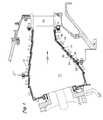
- annular combustor 10 is defined by an inner annular shell 12 and an outer annular shell 14.
- Each shell is formed of a plurality of axially arranged contiguous sections such as first shell section 16 and a second shell section 18.
- Gas flow 20 passes through the combustor entering first stage vanes 22 and first stage blades (not shown).
- Conventional floating wall liner panels 24 are located throughout the majority of the combustor with cooling air passing through the shell opening 26 impinging against the cold side of the liner 24. A portion of the flow passes as flow 28 upstream with respect to the gas flow where it joins cooling flow passing from an upstream panel, passing across the surface of liner panel 24. Another portion of the flow 30 passes out the upstream end of the panel across the surface of a downstream located panel.
- Shell section 18 diverges from shell section 16 with respect to gas flow 20.
- Figure 2 shows how prior art liner panel 32 extends into the gas flow at end 34 creating turbulence 36 which would mix the gas flow from the combustor with the surface flow across downstream panel 38. Also cooling flow 40 issuing from under panel 32 is directed substantially into the gas flow rather than across the surface of panel 38 is desired.
- the second floating liner panel 50 shown in Figure 3 has a second cooling flow space 52 between the shell 18 and the liner 50.
- the height of the flow opening 54, measured perpendicular to the liner, is less at the upstream end, with respect to gas flow 20 than the space 56 between the shell and the panel.
- Cooling air flow 58 passes through opening 60 in the shell impinging against panel 50 where space 52 is in fluid communication with the gas flow 20 at both the upstream and downstream ends. A minor portion of the flow passes upstream past the area 54 or adjoins with flow 62 passing under first floating liner panel 64 which is supported from first shell section 66. The flow passes over extended cooling surface in the form of pins. These pins are shown in Figure 3, and are arranged in an equilateral triangle array.
- the edge 68 of panel 50 is brought closer to shell section 70 because of the smaller space 54. Accordingly the tip 72 of the first liner 64 is brought in closer to the shell.
- the angle between the two contiguous panels is also decreased so that not only is there less turbulence but the flow tends to stay closer to the surface 74 of panel 50. This also decreases the depth of joggle 75.
- Figure 4 is a detail of the panel 50 with tall pins 76 which are located at end 56 and short pins 78 located at end 54. These pins vary from a maximum height of 2.3 mm (0.09 inches) to a minimum of 1.5 mm (0.06 inches). In the center of the panel there are some additional short pins 80 which are used in the conventional manner in the area of inlet flow 18 to permit that flow to spread along the panel. Thus the pins at the upstream end are two thirds the length of the pins at the downstream end.
- pin 76 is located substantially at the end of panel 50 while the small pins 78 has a space 82 at the end of the panel, this space being approximately equal to the diameter of the pin. This space facilitates the turning of the flow at location 84 ( Figure 3) where the flow 86 turns to join flow 62, while the pins 76 at the downstream end improve cooling in this hot area.
Landscapes
- Engineering & Computer Science (AREA)
- Chemical & Material Sciences (AREA)
- Combustion & Propulsion (AREA)
- Mechanical Engineering (AREA)
- General Engineering & Computer Science (AREA)
- Turbine Rotor Nozzle Sealing (AREA)
Claims (4)
- Agencement de revêtement pour un dispositif de combustion de moteur à turbine à gaz ayant un écoulement de gaz (20) à travers ce dernier, comprenant :une coque en arc (12, 14) définissant une zone de combustion (10) ;ladite coque ayant des parties contiguës agencées de façon axiale comprenant une première partie de coque (16) et une seconde partie de coque adjacente en aval (18) ;un premier revêtement flottant (64) supporté à partir de ladite première partie de coque et espacé de cette dernière, et segmenté autour de la circonférence ;un premier espace d'écoulement de refroidissement (62) entre ledit premier revêtement et ladite première coque en communication de fluide avec ledit écoulement de gaz au niveau des deux extrémités amont et aval (72) par rapport audit écoulement de gaz ;un second revêtement flottant (50) supporté à partir de ladite seconde partie de coque et espacé de cette dernière, et segmenté autour de la circonférence ;un second espace d'écoulement de refroidissement (52) entre ledit second revêtement et ladite seconde coque en communication de fluide avec ledit écoulement de gaz au niveau des deux extrémités amont (54) et aval (56) par rapport audit écoulement de gaz ;l'extrémité aval dudit premier revêtement chevauchant l'extrémité amont dudit second revêtement du côté gaz de ces derniers ; caractérisé en ce queladite seconde partie de coque s'écarte de ladite première partie de coque dans le sens de l'écoulement de gaz ; et en ce que ledit second espace de refroidissement a une dimension plus petite perpendiculairement audit revêtement au niveau de l'extrémité amont que l'extrémité aval par rapport à l'écoulement de gaz.
- Agencement de revêtement selon la revendication 1, dans lequel :ledit second revêtement flottant (50) possède une pluralité d'ergots d'un seul tenant (76 à 80) s'étendant vers ladite seconde coque (18) ; etlesdits ergots (78) près de l'extrémité amont (54) étant plus courts que lesdits ergots (76) près de l'extrémité aval (56).
- Agencement de revêtement selon la revendication 2, dans lequel :lesdits ergots (78) au niveau de l'extrémité amont (54) ont deux tiers de la longueur des ergots (76) au niveau de l'extrémité aval (56).
- Agencement de revêtement selon la revendication 2 ou 3, dans lequel :lesdits ergots (76 à 80) ont un espace (82) entre lesdits ergots (78) et l'extrémité amont (54) dudit panneau ; etlesdits ergots n'ont aucun espace entre lesdits ergots (76) et l'extrémité aval (56) dudit panneau.
Applications Claiming Priority (3)
| Application Number | Priority Date | Filing Date | Title |
|---|---|---|---|
| US08/356,089 US5461866A (en) | 1994-12-15 | 1994-12-15 | Gas turbine engine combustion liner float wall cooling arrangement |
| PCT/US1995/015077 WO1996018849A1 (fr) | 1994-12-15 | 1995-11-17 | Agencement de revetement d'un bruleur a deux etages de gazeification |
| US356089 | 2003-01-31 |
Publications (2)
| Publication Number | Publication Date |
|---|---|
| EP0797745A1 EP0797745A1 (fr) | 1997-10-01 |
| EP0797745B1 true EP0797745B1 (fr) | 1999-05-19 |
Family
ID=23400086
Family Applications (1)
| Application Number | Title | Priority Date | Filing Date |
|---|---|---|---|
| EP95944301A Expired - Lifetime EP0797745B1 (fr) | 1994-12-15 | 1995-11-17 | Revetement de chambre de combustion |
Country Status (5)
| Country | Link |
|---|---|
| US (1) | US5461866A (fr) |
| EP (1) | EP0797745B1 (fr) |
| JP (1) | JP3689114B2 (fr) |
| DE (1) | DE69509791T2 (fr) |
| WO (1) | WO1996018849A1 (fr) |
Families Citing this family (36)
| Publication number | Priority date | Publication date | Assignee | Title |
|---|---|---|---|---|
| US5577379A (en) * | 1994-12-15 | 1996-11-26 | United Technologies Corporation | Fuel nozzle guide retainer assembly |
| WO1999014532A1 (fr) * | 1997-09-12 | 1999-03-25 | Hitachi, Ltd. | Chambre de combustion pour turbine a gaz et structure de chemise associee |
| US6042315A (en) * | 1997-10-06 | 2000-03-28 | United Technologies Corporation | Fastener |
| US6045310A (en) * | 1997-10-06 | 2000-04-04 | United Technologies Corporation | Composite fastener for use in high temperature environments |
| EP1312865A1 (fr) * | 2001-11-15 | 2003-05-21 | Siemens Aktiengesellschaft | Chambre de combustion annulaire de turbine à gaz |
| US6638013B2 (en) | 2002-02-25 | 2003-10-28 | Honeywell International Inc. | Thermally isolated housing in gas turbine engine |
| US6719524B2 (en) | 2002-02-25 | 2004-04-13 | Honeywell International Inc. | Method of forming a thermally isolated gas turbine engine housing |
| US7010921B2 (en) * | 2004-06-01 | 2006-03-14 | General Electric Company | Method and apparatus for cooling combustor liner and transition piece of a gas turbine |
| GB2420614B (en) * | 2004-11-30 | 2009-06-03 | Alstom Technology Ltd | Tile and exo-skeleton tile structure |
| US8051663B2 (en) | 2007-11-09 | 2011-11-08 | United Technologies Corp. | Gas turbine engine systems involving cooling of combustion section liners |
| US8109099B2 (en) * | 2008-07-09 | 2012-02-07 | United Technologies Corporation | Flow sleeve with tabbed direct combustion liner cooling air |
| US8245514B2 (en) * | 2008-07-10 | 2012-08-21 | United Technologies Corporation | Combustion liner for a gas turbine engine including heat transfer columns to increase cooling of a hula seal at the transition duct region |
| JP5506834B2 (ja) * | 2012-01-27 | 2014-05-28 | 三菱重工業株式会社 | ガスタービン |
| US8910378B2 (en) * | 2012-05-01 | 2014-12-16 | United Technologies Corporation | Method for working of combustor float wall panels |
| US9217568B2 (en) | 2012-06-07 | 2015-12-22 | United Technologies Corporation | Combustor liner with decreased liner cooling |
| US9239165B2 (en) | 2012-06-07 | 2016-01-19 | United Technologies Corporation | Combustor liner with convergent cooling channel |
| US9335049B2 (en) | 2012-06-07 | 2016-05-10 | United Technologies Corporation | Combustor liner with reduced cooling dilution openings |
| US9243801B2 (en) | 2012-06-07 | 2016-01-26 | United Technologies Corporation | Combustor liner with improved film cooling |
| US9334756B2 (en) | 2012-09-28 | 2016-05-10 | United Technologies Corporation | Liner and method of assembly |
| WO2015050879A1 (fr) | 2013-10-04 | 2015-04-09 | United Technologies Corporation | Panneau de protection contre la chaleur doté d'assemblages par recouvrement pour chambre de combustion de moteur de turbine |
| EP3058201B1 (fr) * | 2013-10-18 | 2018-07-18 | United Technologies Corporation | Paroi de chambre de combustion ayant un ou plusieurs éléments de refroidissement dans une cavité de refroidissement |
| EP3071885B1 (fr) | 2013-11-21 | 2020-03-11 | United Technologies Corporation | Structure à parois multiples pour moteur à turbine dotée d'éléments de refroidissement internes |
| EP3071816B1 (fr) | 2013-11-21 | 2019-09-18 | United Technologies Corporation | Refroidissement d'une structure à parois multiples d'un moteur à turbine |
| EP3071887B1 (fr) | 2013-11-22 | 2020-03-11 | United Technologies Corporation | Structure à parois multiples d'un moteur à turbine avec éléments de refroidissement |
| EP3967854B1 (fr) | 2013-11-25 | 2023-07-05 | Raytheon Technologies Corporation | Agencement pour un moteur à turbine |
| WO2015085065A1 (fr) | 2013-12-05 | 2015-06-11 | United Technologies Corporation | Refroidissement d'un corps à ouverture de refroidissement rapide d'une paroi de chambre de combustion |
| WO2015085080A1 (fr) | 2013-12-06 | 2015-06-11 | United Technologies Corporation | Refroidissement d'un corps à ouverture d'allumeur d'une paroi de chambre de combustion |
| US10386068B2 (en) | 2013-12-06 | 2019-08-20 | United Technologies Corporation | Cooling a quench aperture body of a combustor wall |
| US10697636B2 (en) | 2013-12-06 | 2020-06-30 | Raytheon Technologies Corporation | Cooling a combustor heat shield proximate a quench aperture |
| US10378768B2 (en) | 2013-12-06 | 2019-08-13 | United Technologies Corporation | Combustor quench aperture cooling |
| WO2015117139A1 (fr) | 2014-02-03 | 2015-08-06 | United Technologies Corporation | Chemise thermique étagée pour une chambre de combustion de moteur à turbine |
| US10533745B2 (en) | 2014-02-03 | 2020-01-14 | United Technologies Corporation | Film cooling a combustor wall of a turbine engine |
| DE102014204482A1 (de) * | 2014-03-11 | 2015-09-17 | Rolls-Royce Deutschland Ltd & Co Kg | Brennkammer einer Gasturbine |
| CN105333456B (zh) * | 2014-07-31 | 2017-11-10 | 中国航发商用航空发动机有限责任公司 | 用于火焰筒的浮动壁瓦块及其浮动壁 |
| US10480787B2 (en) | 2015-03-26 | 2019-11-19 | United Technologies Corporation | Combustor wall cooling channel formed by additive manufacturing |
| GB201603166D0 (en) * | 2016-02-24 | 2016-04-06 | Rolls Royce Plc | A combustion chamber |
Family Cites Families (13)
| Publication number | Priority date | Publication date | Assignee | Title |
|---|---|---|---|---|
| US4614082A (en) * | 1972-12-19 | 1986-09-30 | General Electric Company | Combustion chamber construction |
| US4109459A (en) * | 1974-07-19 | 1978-08-29 | General Electric Company | Double walled impingement cooled combustor |
| FR2340453A1 (fr) * | 1976-02-06 | 1977-09-02 | Snecma | Corps de chambre de combustion, notamment pour turboreacteurs |
| US4302941A (en) * | 1980-04-02 | 1981-12-01 | United Technologies Corporation | Combuster liner construction for gas turbine engine |
| GB2087065B (en) * | 1980-11-08 | 1984-11-07 | Rolls Royce | Wall structure for a combustion chamber |
| US4567730A (en) * | 1983-10-03 | 1986-02-04 | General Electric Company | Shielded combustor |
| US4790140A (en) * | 1985-01-18 | 1988-12-13 | Ishikawajima-Harima Jukogyo Kabushiki Kaisha | Liner cooling construction for gas turbine combustor or the like |
| JPH0752014B2 (ja) * | 1986-03-20 | 1995-06-05 | 株式会社日立製作所 | ガスタ−ビン燃焼器 |
| FR2624953B1 (fr) * | 1987-12-16 | 1990-04-20 | Snecma | Chambre de combustion, pour turbomachines, possedant un convergent a doubles parois |
| US4916906A (en) * | 1988-03-25 | 1990-04-17 | General Electric Company | Breach-cooled structure |
| US5083422A (en) * | 1988-03-25 | 1992-01-28 | General Electric Company | Method of breach cooling |
| US5123248A (en) * | 1990-03-28 | 1992-06-23 | General Electric Company | Low emissions combustor |
| DE4239856A1 (de) * | 1992-11-27 | 1994-06-01 | Asea Brown Boveri | Gasturbinenbrennkammer |
-
1994
- 1994-12-15 US US08/356,089 patent/US5461866A/en not_active Expired - Lifetime
-
1995
- 1995-11-17 WO PCT/US1995/015077 patent/WO1996018849A1/fr not_active Ceased
- 1995-11-17 EP EP95944301A patent/EP0797745B1/fr not_active Expired - Lifetime
- 1995-11-17 JP JP51888096A patent/JP3689114B2/ja not_active Expired - Lifetime
- 1995-11-17 DE DE69509791T patent/DE69509791T2/de not_active Expired - Lifetime
Also Published As
| Publication number | Publication date |
|---|---|
| JPH10510908A (ja) | 1998-10-20 |
| EP0797745A1 (fr) | 1997-10-01 |
| JP3689114B2 (ja) | 2005-08-31 |
| US5461866A (en) | 1995-10-31 |
| WO1996018849A1 (fr) | 1996-06-20 |
| DE69509791D1 (de) | 1999-06-24 |
| DE69509791T2 (de) | 1999-12-23 |
Similar Documents
| Publication | Publication Date | Title |
|---|---|---|
| EP0797745B1 (fr) | Revetement de chambre de combustion | |
| KR101044662B1 (ko) | 성형 냉각 홀을 구비한 유출 냉각 전이 덕트 | |
| US5281084A (en) | Curved film cooling holes for gas turbine engine vanes | |
| US4066214A (en) | Gas turbine exhaust nozzle for controlled temperature flow across adjoining airfoils | |
| CA2583400C (fr) | Chambre de combustion de turbine a gaz avec refroidisdement ameliore | |
| US5209067A (en) | Gas turbine combustion chamber wall structure for minimizing cooling film disturbances | |
| US7637716B2 (en) | Platform cooling arrangement for the nozzle guide vane stator of a gas turbine | |
| US5518311A (en) | Mixing chamber with vortex generators for flowing gases | |
| CN103459928B (zh) | 超低排放物燃气轮机燃烧室 | |
| US8683806B2 (en) | Chamber-bottom baffle, combustion chamber comprising same and gas turbine engine fitted therewith | |
| RU99111740A (ru) | Охлаждающее устройство профильной части лопатки газотурбинного двигателя | |
| US12152778B1 (en) | Combustion liner | |
| JP2008510955A (ja) | 熱保護体のない燃焼器および燃焼器ライナの冷却 | |
| US5609030A (en) | Combustion chamber with temperature graduated combustion flow | |
| EP1225308B1 (fr) | Cartèr divisible pour une turbine à gaz | |
| US5144795A (en) | Fluid cooled hot duct liner structure | |
| CA1204293A (fr) | Chambre de combustion a faible emission de fumees pour turbines d'installations terrestres | |
| JPS5834725B2 (ja) | ガスタ−ビンエンジン | |
| US7628020B2 (en) | Combustor with improved swirl | |
| JPS6335897B2 (fr) | ||
| EP0849531B1 (fr) | Procédé de combustion à faible émission de tonalités acoustiques | |
| JP2008512597A (ja) | 燃焼器の出口ダクトの冷却 | |
| KR20110112239A (ko) | 경사 시일 냉각 시스템 | |
| EP0963534B1 (fr) | Dispositif stabilisateur de flamme destine aux dispositifs de postcombustion des turbines a gaz | |
| US5150570A (en) | Unitized fuel manifold and injector for a turbine engine |
Legal Events
| Date | Code | Title | Description |
|---|---|---|---|
| PUAI | Public reference made under article 153(3) epc to a published international application that has entered the european phase |
Free format text: ORIGINAL CODE: 0009012 |
|
| 17P | Request for examination filed |
Effective date: 19970715 |
|
| AK | Designated contracting states |
Kind code of ref document: A1 Designated state(s): DE FR GB |
|
| GRAG | Despatch of communication of intention to grant |
Free format text: ORIGINAL CODE: EPIDOS AGRA |
|
| 17Q | First examination report despatched |
Effective date: 19980708 |
|
| GRAG | Despatch of communication of intention to grant |
Free format text: ORIGINAL CODE: EPIDOS AGRA |
|
| GRAH | Despatch of communication of intention to grant a patent |
Free format text: ORIGINAL CODE: EPIDOS IGRA |
|
| GRAH | Despatch of communication of intention to grant a patent |
Free format text: ORIGINAL CODE: EPIDOS IGRA |
|
| GRAA | (expected) grant |
Free format text: ORIGINAL CODE: 0009210 |
|
| AK | Designated contracting states |
Kind code of ref document: B1 Designated state(s): DE FR GB |
|
| ET | Fr: translation filed | ||
| REF | Corresponds to: |
Ref document number: 69509791 Country of ref document: DE Date of ref document: 19990624 |
|
| PLBE | No opposition filed within time limit |
Free format text: ORIGINAL CODE: 0009261 |
|
| STAA | Information on the status of an ep patent application or granted ep patent |
Free format text: STATUS: NO OPPOSITION FILED WITHIN TIME LIMIT |
|
| 26N | No opposition filed | ||
| REG | Reference to a national code |
Ref country code: GB Ref legal event code: IF02 |
|
| PGFP | Annual fee paid to national office [announced via postgrant information from national office to epo] |
Ref country code: FR Payment date: 20081106 Year of fee payment: 14 |
|
| REG | Reference to a national code |
Ref country code: FR Ref legal event code: ST Effective date: 20100730 |
|
| PG25 | Lapsed in a contracting state [announced via postgrant information from national office to epo] |
Ref country code: FR Free format text: LAPSE BECAUSE OF NON-PAYMENT OF DUE FEES Effective date: 20091130 |
|
| PGFP | Annual fee paid to national office [announced via postgrant information from national office to epo] |
Ref country code: DE Payment date: 20131113 Year of fee payment: 19 Ref country code: GB Payment date: 20131113 Year of fee payment: 19 |
|
| REG | Reference to a national code |
Ref country code: DE Ref legal event code: R119 Ref document number: 69509791 Country of ref document: DE |
|
| GBPC | Gb: european patent ceased through non-payment of renewal fee |
Effective date: 20141117 |
|
| PG25 | Lapsed in a contracting state [announced via postgrant information from national office to epo] |
Ref country code: GB Free format text: LAPSE BECAUSE OF NON-PAYMENT OF DUE FEES Effective date: 20141117 Ref country code: DE Free format text: LAPSE BECAUSE OF NON-PAYMENT OF DUE FEES Effective date: 20150602 |