EP0798502A1 - Capteur de position ou de déplacement - Google Patents
Capteur de position ou de déplacement Download PDFInfo
- Publication number
- EP0798502A1 EP0798502A1 EP97103500A EP97103500A EP0798502A1 EP 0798502 A1 EP0798502 A1 EP 0798502A1 EP 97103500 A EP97103500 A EP 97103500A EP 97103500 A EP97103500 A EP 97103500A EP 0798502 A1 EP0798502 A1 EP 0798502A1
- Authority
- EP
- European Patent Office
- Prior art keywords
- signal
- displacement sensor
- gate
- sensor according
- exclusive
- Prior art date
- Legal status (The legal status is an assumption and is not a legal conclusion. Google has not performed a legal analysis and makes no representation as to the accuracy of the status listed.)
- Granted
Links
- 238000006073 displacement reaction Methods 0.000 title claims description 17
- 230000001939 inductive effect Effects 0.000 claims abstract description 14
- 230000010363 phase shift Effects 0.000 claims abstract description 14
- 239000003990 capacitor Substances 0.000 claims abstract description 12
- 238000011156 evaluation Methods 0.000 claims description 20
- 230000005284 excitation Effects 0.000 claims description 13
- 230000001419 dependent effect Effects 0.000 claims description 3
- 238000010586 diagram Methods 0.000 description 5
- 238000012546 transfer Methods 0.000 description 3
- 238000001514 detection method Methods 0.000 description 2
- 238000005070 sampling Methods 0.000 description 2
- 238000013016 damping Methods 0.000 description 1
- 238000013461 design Methods 0.000 description 1
- 238000011161 development Methods 0.000 description 1
- 230000018109 developmental process Effects 0.000 description 1
- 239000000696 magnetic material Substances 0.000 description 1
- 230000003534 oscillatory effect Effects 0.000 description 1
- 238000012545 processing Methods 0.000 description 1
- 230000001360 synchronised effect Effects 0.000 description 1
Images


Classifications
-
- G—PHYSICS
- G01—MEASURING; TESTING
- G01D—MEASURING NOT SPECIALLY ADAPTED FOR A SPECIFIC VARIABLE; ARRANGEMENTS FOR MEASURING TWO OR MORE VARIABLES NOT COVERED IN A SINGLE OTHER SUBCLASS; TARIFF METERING APPARATUS; MEASURING OR TESTING NOT OTHERWISE PROVIDED FOR
- G01D5/00—Mechanical means for transferring the output of a sensing member; Means for converting the output of a sensing member to another variable where the form or nature of the sensing member does not constrain the means for converting; Transducers not specially adapted for a specific variable
- G01D5/12—Mechanical means for transferring the output of a sensing member; Means for converting the output of a sensing member to another variable where the form or nature of the sensing member does not constrain the means for converting; Transducers not specially adapted for a specific variable using electric or magnetic means
- G01D5/14—Mechanical means for transferring the output of a sensing member; Means for converting the output of a sensing member to another variable where the form or nature of the sensing member does not constrain the means for converting; Transducers not specially adapted for a specific variable using electric or magnetic means influencing the magnitude of a current or voltage
- G01D5/20—Mechanical means for transferring the output of a sensing member; Means for converting the output of a sensing member to another variable where the form or nature of the sensing member does not constrain the means for converting; Transducers not specially adapted for a specific variable using electric or magnetic means influencing the magnitude of a current or voltage by varying inductance, e.g. by a movable armature
- G01D5/22—Mechanical means for transferring the output of a sensing member; Means for converting the output of a sensing member to another variable where the form or nature of the sensing member does not constrain the means for converting; Transducers not specially adapted for a specific variable using electric or magnetic means influencing the magnitude of a current or voltage by varying inductance, e.g. by a movable armature differentially influencing two coils
- G01D5/2208—Mechanical means for transferring the output of a sensing member; Means for converting the output of a sensing member to another variable where the form or nature of the sensing member does not constrain the means for converting; Transducers not specially adapted for a specific variable using electric or magnetic means influencing the magnitude of a current or voltage by varying inductance, e.g. by a movable armature differentially influencing two coils by influencing the self-induction of the coils
- G01D5/2216—Mechanical means for transferring the output of a sensing member; Means for converting the output of a sensing member to another variable where the form or nature of the sensing member does not constrain the means for converting; Transducers not specially adapted for a specific variable using electric or magnetic means influencing the magnitude of a current or voltage by varying inductance, e.g. by a movable armature differentially influencing two coils by influencing the self-induction of the coils by a movable ferromagnetic element, e.g. a core
-
- F—MECHANICAL ENGINEERING; LIGHTING; HEATING; WEAPONS; BLASTING
- F16—ENGINEERING ELEMENTS AND UNITS; GENERAL MEASURES FOR PRODUCING AND MAINTAINING EFFECTIVE FUNCTIONING OF MACHINES OR INSTALLATIONS; THERMAL INSULATION IN GENERAL
- F16K—VALVES; TAPS; COCKS; ACTUATING-FLOATS; DEVICES FOR VENTING OR AERATING
- F16K37/00—Special means in or on valves or other cut-off apparatus for indicating or recording operation thereof, or for enabling an alarm to be given
- F16K37/0025—Electrical or magnetic means
- F16K37/0041—Electrical or magnetic means for measuring valve parameters
Definitions
- the invention relates to a position or displacement sensor, in particular for a hydraulic or pneumatic control valve, according to the preamble of the main claim.
- a control valve is already known from EP 0 183 919 B1, in which the position of the valve piston is measured via an inductive measuring system, which is designed in principle as a differential throttle or differential transformer.
- an inductive measuring system which is designed in principle as a differential throttle or differential transformer.
- a displacement transducer core connected to the piston or slide of the valve in a pressure pipe made of non-magnetic material in the area of influence of the inductive arrangement attached around the pressure pipe.
- the maximum evaluable phase shift is only 90 ° and extends over a relatively wide range of an inductance change, which leads to a limited resolution.
- the position or displacement sensor of the generic type according to the invention with the characterizing features of claim 1 and the further developments according to the dependent claims is advantageous in that with the application of a second-order circuit according to the invention, in particular for a quick and rigid position control of a control valve, shorter sampling times than in the case of State of the art can be realized.
- the phase shift that can be achieved when evaluating the phase shift caused by a change in position of an excitation signal generated by an AC voltage source is 180 ° compared to 90 ° in a first-order circuit with an interconnection of inductors and ohmic resistors. Due to the relatively large achievable phase shift, the resulting time windows in the digital evaluation or control circuit are also considerably enlarged, and the resolution of the displacement or position sensor is thus advantageously improved with short sampling times.
- the excitation frequency for the oscillatory circuit 2nd order should be in the vicinity of the resonance frequency of this circuit with a central position of the reciprocating piston.
- An advantageous digital evaluation of the output signals of the coil arrangement is possible with the examples for an evaluation circuit specified in the subclaims, an accurate detection of the absolute position of, for example, a reciprocating piston including the direction of the deviation from a central position being ensured.
- the evaluation of the above-mentioned time window can take place within a period of the excitation signal generated by the AC voltage source either twice or only once in the case of asymmetrical signal profiles.
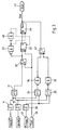
- a valve part 1 is shown as a section of a known hydraulic or pneumatic control valve which has a pressure pipe 2 with a pressure medium.
- a rod 3 is connected to a valve slide, not shown, to which a piston 4 is connected as a displacement transducer core.
- a first coil 5 and a second coil 6 outside the pressure tube 2 both of which are plugged onto the pressure tube 2.
- One connection of the coils 5 and 6 are connected to the output of an AC voltage source 17, which is either a sinusoidal output signal U * sin ⁇ t or preferably also emits a square-wave signal.
- the other connection of the first coil 5 is connected to a capacitor 7 and the other connection of the second coil 6 is connected to ground via a capacitor 8.
- the connection point between the coil 5 and the capacitor 7 is linked to a comparator 9 and the connection point between the coil 6 and the capacitor 8 is linked to a comparator 10.
- the output of the comparator 9 is connected on the one hand to an input of an exclusive OR gate 14 and on the other hand to the set input D of a flip-flop 13.
- the output of the comparator 10 is connected to the further input of the exclusive OR gate 14.
- the output of the exclusive OR gate 14 is connected to the start-stop input of a counter 15, the clock input of the Counter 15 is connected to the output of a clock generator 16.
- the counting result between the start and the stop signal can be tapped in serial or in parallel form.
- This counting result can be fed to a further digital circuit or a computer, wherein digital control modules can also be acted upon directly with this output signal.
- a sign or direction signal can also be tapped, which indicates in which direction the piston 4 is shifted from its rest position between the two coils 5 and 6.
- the AC voltage of the AC voltage source 17 as an excitation signal causes a coil current in the coils 5 and 6, which leads to voltage drops at the connection points to the capacitors 7 and 8.
- the phase shift of these two voltages relative to one another is a measure of the position of the piston 4 outside the central position between the two coils 5 and 6.
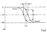
- the phase response ⁇ as a function of an inductance change caused by such a change in position is shown in FIG. This change in inductance caused by a piston movement correlates here with a frequency change ⁇ f, the phase change ⁇ taking place in the region of the resonance ⁇ o .
- the length of the time window .DELTA.t is determined with the digital counter 15, with a direction signal of the phase change being additionally detected with the flip-flop 13 and also being available for further processing.
- This evaluation of this switching time shift which is known per se from EP 0 183 919 B1, thus allows the position or displacement signal of the piston 4 to be detected.
- the maximum phase shift that can be evaluated is 180 °, as can be seen from FIG significantly increased resolution is achieved.
- FIG. 3 In a second exemplary embodiment of an evaluation circuit according to FIG. 3, the coils 5 and 6 (cf. FIG. 1) are shown schematically; In contrast to the exemplary embodiment according to FIG. 1, however, the output signals of the comparators 9 and 10 are fed to the set input D of a flip-flop 32 via an exclusive-OR gate 31 (XOR).
- XOR exclusive-OR gate
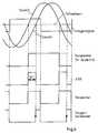
- the output signals of the coils 5 and 6 and the excitation signal converted by a comparator 30 are shown above in this diagram.
- the output signal of the comparator 9 is drawn underneath with a continuous line and the output signal of the comparator 10 with an interrupted line. From this, the exclusive OR gate 31 is used to generate a signal for the duration of this time window .DELTA.t by one of the comparators 9 or 10 0 "signal and one at the other 1 "signal generated becomes.
- the length of the time window ⁇ t is therefore also a measure of the phase shift between the output signals of the coils 5 and 6.
- this time window ⁇ t is recorded with a counter 33.
- the counter 33 like the flip-flop 32, is controlled synchronously with the output signal of the clock generator 16, so that the time window ⁇ t to be evaluated can be synchronized with the counter 33 via the flip-flop 32.
- the counter 15 (FIG. 1) or counter 33 (FIG. 3) is caused to set the time window ⁇ t twice during the period of the output signal of the coils 5 and 6 to count.
- a change of sign cannot be recognized here at first, since a sign signal is only generated once during a period.
- the excitation signal of the AC voltage source 17 is also used for the evaluation.
- a register 38 is connected downstream of the counter 33.
- the transfer of the meter readings to register 38 and that Subsequent resetting of the counter 33 takes place in this exemplary embodiment via two series-connected NAND elements 39 and 40.
- the first NAND element 39 ensures that the transfer of the counter reading to the register 38 starts after the end of the time window ⁇ t, ensuring that due to the switching time of the NAND gate 39 the counting in the counter 33 has also ended.
- the reset pulse of the second NAND element 40 also takes place in such a way that the transfer to the register has been safely ended due to the switching time. If the existing switching times of the NAND gates 39 and 40 are not sufficient, additional AND gates can be added here to delay the time.
- an evaluable position signal is therefore continuously readable from the register 38, an additionally applied sign signal also indicating the direction of a shift from the central position.
- This sign signal (see also FIG. 4) is formed twice from the output signals of the NAND gates 36 and 37 via a flip-flop 42 during the period of the output signals of the coils 5 and 6.
- an evaluation circuit is implemented which, in contrast to the previously described, only carries out a one-time evaluation of the phase position of the output signals of the coils 5 and 6 during a period.
- This exemplary embodiment is applied to sensors in which, due to an asymmetry of the coil signal profiles, two time windows ⁇ t of different lengths would arise in the course of a period and therefore no clear detection of a position signal with a two-time evaluation is possible.
- the output signal of the exclusive OR gate 31 is linked to the excitation signal of the AC voltage source 17 via an AND gate 43 and fed to the counter 33 via the flip-flop 42.
- the sign signal can be formed directly from the output signals of the comparators 9 and 10 via the flip-flop 42.
Landscapes
- Engineering & Computer Science (AREA)
- General Engineering & Computer Science (AREA)
- Physics & Mathematics (AREA)
- General Physics & Mathematics (AREA)
- Mechanical Engineering (AREA)
- Measurement Of Length, Angles, Or The Like Using Electric Or Magnetic Means (AREA)
Applications Claiming Priority (2)
| Application Number | Priority Date | Filing Date | Title |
|---|---|---|---|
| DE19612835A DE19612835A1 (de) | 1996-03-30 | 1996-03-30 | Lage- oder Wegsensor |
| DE19612835 | 1996-03-30 |
Publications (2)
| Publication Number | Publication Date |
|---|---|
| EP0798502A1 true EP0798502A1 (fr) | 1997-10-01 |
| EP0798502B1 EP0798502B1 (fr) | 2001-08-01 |
Family
ID=7790042
Family Applications (1)
| Application Number | Title | Priority Date | Filing Date |
|---|---|---|---|
| EP97103500A Expired - Lifetime EP0798502B1 (fr) | 1996-03-30 | 1997-03-04 | Capteur de position ou de déplacement |
Country Status (2)
| Country | Link |
|---|---|
| EP (1) | EP0798502B1 (fr) |
| DE (2) | DE19612835A1 (fr) |
Cited By (1)
| Publication number | Priority date | Publication date | Assignee | Title |
|---|---|---|---|---|
| CN114687980A (zh) * | 2020-12-29 | 2022-07-01 | 三一汽车制造有限公司 | 泵送设备、泵送系统及其换向参数调节方法 |
Families Citing this family (8)
| Publication number | Priority date | Publication date | Assignee | Title |
|---|---|---|---|---|
| DE19756637A1 (de) | 1997-12-19 | 1999-06-24 | Zahnradfabrik Friedrichshafen | Schalteinrichtung |
| DE19756639A1 (de) | 1997-12-19 | 1999-06-24 | Zahnradfabrik Friedrichshafen | Schalteinrichtung |
| DE10051048A1 (de) | 2000-10-14 | 2002-04-18 | Wabco Gmbh & Co Ohg | Meßverfahren für eine Mechatronik |
| DE10132666C2 (de) * | 2001-07-05 | 2003-07-10 | Vogt Electronic Ag | Positionssensor eines Ventils |
| RU2221988C1 (ru) * | 2002-11-11 | 2004-01-20 | Физико-технический институт Уральского отделения РАН | Индуктивный датчик перемещений |
| DE102009009061A1 (de) * | 2009-01-21 | 2010-07-29 | Gerd Reime | Verfahren zum induktiven Erzeugen eines elektrischen Messsignals sowie zugehörige Sensorvorrichtung |
| DE102015005123A1 (de) | 2015-04-22 | 2016-10-27 | Gpi Gesellschaft Für Prüfstanduntersuchungen Und Ingenieurdienstleistungen Mbh | Zylinderkopfventileinheit |
| FR3125333B1 (fr) | 2021-07-16 | 2023-06-09 | Safran Electronics & Defense | Procédé et dispositif de prédiction de dysfonctionnements d’une électrovanne à double circuit |
Citations (2)
| Publication number | Priority date | Publication date | Assignee | Title |
|---|---|---|---|---|
| US3967064A (en) * | 1972-11-16 | 1976-06-29 | Systron Donner Corporation | Low noise electronic circuit, transducer using the same, and method |
| EP0183919A1 (fr) * | 1984-10-10 | 1986-06-11 | Robert Bosch Gmbh | Soupape équipée d'un dispositif de commutation pour déterminer la position de cette soupape |
-
1996
- 1996-03-30 DE DE19612835A patent/DE19612835A1/de not_active Withdrawn
-
1997
- 1997-03-04 DE DE59704160T patent/DE59704160D1/de not_active Expired - Fee Related
- 1997-03-04 EP EP97103500A patent/EP0798502B1/fr not_active Expired - Lifetime
Patent Citations (2)
| Publication number | Priority date | Publication date | Assignee | Title |
|---|---|---|---|---|
| US3967064A (en) * | 1972-11-16 | 1976-06-29 | Systron Donner Corporation | Low noise electronic circuit, transducer using the same, and method |
| EP0183919A1 (fr) * | 1984-10-10 | 1986-06-11 | Robert Bosch Gmbh | Soupape équipée d'un dispositif de commutation pour déterminer la position de cette soupape |
Cited By (2)
| Publication number | Priority date | Publication date | Assignee | Title |
|---|---|---|---|---|
| CN114687980A (zh) * | 2020-12-29 | 2022-07-01 | 三一汽车制造有限公司 | 泵送设备、泵送系统及其换向参数调节方法 |
| CN114687980B (zh) * | 2020-12-29 | 2023-10-10 | 三一汽车制造有限公司 | 泵送设备、泵送系统及其换向参数调节方法 |
Also Published As
| Publication number | Publication date |
|---|---|
| DE19612835A1 (de) | 1997-10-02 |
| DE59704160D1 (de) | 2001-09-06 |
| EP0798502B1 (fr) | 2001-08-01 |
Similar Documents
| Publication | Publication Date | Title |
|---|---|---|
| DE19818799C2 (de) | Verfahren und Vorrichtung zum Messen von Winkeln | |
| EP1969320B1 (fr) | Circuit d'évaluation et de compensation d'un capteur inductif de déplacement | |
| EP0726448B1 (fr) | Capteur magnétique de position | |
| DE3436681A1 (de) | Kapazitives verschiebungsmessgeraet | |
| DE102017222674A1 (de) | Wegsensor | |
| DE2944033C2 (de) | Meßeinrichtung zur Ermittlung der Drehbewegung eines Drehkörpers | |
| EP0798502B1 (fr) | Capteur de position ou de déplacement | |
| DE4237879A1 (de) | Auswerteschaltung für einen Induktivsensor | |
| DE2158320B2 (de) | Vorrichtung zur berührungsfreien relativen Abstandsmessung | |
| EP0065762B1 (fr) | Méthode et arrangement de circuit pour mesurer un champ magnétique, spécialement le champ magnétique terrestre | |
| EP0447653A1 (fr) | Capteur inductif de position | |
| DE102007036202A1 (de) | Prüf- und Simulationsschaltung für Magnetfeldsensoren | |
| EP0183919B1 (fr) | Soupape équipée d'un dispositif de commutation pour déterminer la position de cette soupape | |
| DE4137695C2 (de) | Sensoranordnung zur Feststellung des Bewegungszustandes eines Rotors | |
| DE102008056700A1 (de) | Drehzahlsensor zum Ermitteln von "langsamen (Nulldrehzahl) und schnellen" Drehzahlen sowie zur gleichzeitigen Ermittlung der Drehrichtung | |
| EP0460407B1 (fr) | Circuit pour capteur | |
| EP0522520A1 (fr) | Appareil pour mesure de distances pour véhicules | |
| EP3893006A1 (fr) | Agencement de circuits électriques et procédé de mesure de courant différentiel galvaniquement isolée, sensible à tous les courants, à haute résolution | |
| EP0065589B1 (fr) | Procédé et dispositif pour déterminer un champ magnétique | |
| DE10124760A1 (de) | Verfahren zur kontaktlosen, linearen Positionsmessung | |
| EP3617658A1 (fr) | Capteur | |
| EP3798600B1 (fr) | Dispositif de mesure et procédé de détermination d'une pression | |
| DE2949815C2 (fr) | ||
| DE102021000157A1 (de) | lnduktive Annäherungssensoreinheit und Verfahren zur Störungsüberprüfung bei einer induktiven Annäherungssensoreinheit | |
| DE102005034859A1 (de) | Meßanordnung zur Messung des Induktivitäts- und des Widerstandswertes eines induktiven Sensors |
Legal Events
| Date | Code | Title | Description |
|---|---|---|---|
| PUAI | Public reference made under article 153(3) epc to a published international application that has entered the european phase |
Free format text: ORIGINAL CODE: 0009012 |
|
| AK | Designated contracting states |
Kind code of ref document: A1 Designated state(s): DE FR GB IT |
|
| 17P | Request for examination filed |
Effective date: 19980401 |
|
| 17Q | First examination report despatched |
Effective date: 19980721 |
|
| GRAG | Despatch of communication of intention to grant |
Free format text: ORIGINAL CODE: EPIDOS AGRA |
|
| GRAG | Despatch of communication of intention to grant |
Free format text: ORIGINAL CODE: EPIDOS AGRA |
|
| GRAH | Despatch of communication of intention to grant a patent |
Free format text: ORIGINAL CODE: EPIDOS IGRA |
|
| GRAH | Despatch of communication of intention to grant a patent |
Free format text: ORIGINAL CODE: EPIDOS IGRA |
|
| GRAA | (expected) grant |
Free format text: ORIGINAL CODE: 0009210 |
|
| AK | Designated contracting states |
Kind code of ref document: B1 Designated state(s): DE FR GB IT |
|
| REF | Corresponds to: |
Ref document number: 59704160 Country of ref document: DE Date of ref document: 20010906 |
|
| ET | Fr: translation filed | ||
| GBT | Gb: translation of ep patent filed (gb section 77(6)(a)/1977) |
Effective date: 20011004 |
|
| REG | Reference to a national code |
Ref country code: GB Ref legal event code: IF02 |
|
| PLBE | No opposition filed within time limit |
Free format text: ORIGINAL CODE: 0009261 |
|
| STAA | Information on the status of an ep patent application or granted ep patent |
Free format text: STATUS: NO OPPOSITION FILED WITHIN TIME LIMIT |
|
| 26N | No opposition filed | ||
| PGFP | Annual fee paid to national office [announced via postgrant information from national office to epo] |
Ref country code: GB Payment date: 20040305 Year of fee payment: 8 |
|
| PGFP | Annual fee paid to national office [announced via postgrant information from national office to epo] |
Ref country code: FR Payment date: 20040318 Year of fee payment: 8 |
|
| PGFP | Annual fee paid to national office [announced via postgrant information from national office to epo] |
Ref country code: DE Payment date: 20040517 Year of fee payment: 8 |
|
| PG25 | Lapsed in a contracting state [announced via postgrant information from national office to epo] |
Ref country code: IT Free format text: LAPSE BECAUSE OF NON-PAYMENT OF DUE FEES;WARNING: LAPSES OF ITALIAN PATENTS WITH EFFECTIVE DATE BEFORE 2007 MAY HAVE OCCURRED AT ANY TIME BEFORE 2007. THE CORRECT EFFECTIVE DATE MAY BE DIFFERENT FROM THE ONE RECORDED. Effective date: 20050304 Ref country code: GB Free format text: LAPSE BECAUSE OF NON-PAYMENT OF DUE FEES Effective date: 20050304 |
|
| PG25 | Lapsed in a contracting state [announced via postgrant information from national office to epo] |
Ref country code: DE Free format text: LAPSE BECAUSE OF NON-PAYMENT OF DUE FEES Effective date: 20051001 |
|
| GBPC | Gb: european patent ceased through non-payment of renewal fee |
Effective date: 20050304 |
|
| PG25 | Lapsed in a contracting state [announced via postgrant information from national office to epo] |
Ref country code: FR Free format text: LAPSE BECAUSE OF NON-PAYMENT OF DUE FEES Effective date: 20051130 |
|
| REG | Reference to a national code |
Ref country code: FR Ref legal event code: ST Effective date: 20051130 |