EP0798557A2 - Capteur de gaz et méthode pour mesurer la quantité de composés spécifiques dans un gaz de mesure - Google Patents
Capteur de gaz et méthode pour mesurer la quantité de composés spécifiques dans un gaz de mesure Download PDFInfo
- Publication number
- EP0798557A2 EP0798557A2 EP97302000A EP97302000A EP0798557A2 EP 0798557 A2 EP0798557 A2 EP 0798557A2 EP 97302000 A EP97302000 A EP 97302000A EP 97302000 A EP97302000 A EP 97302000A EP 0798557 A2 EP0798557 A2 EP 0798557A2
- Authority
- EP
- European Patent Office
- Prior art keywords
- measuring
- pump
- gas
- solid electrolyte
- measuring gas
- Prior art date
- Legal status (The legal status is an assumption and is not a legal conclusion. Google has not performed a legal analysis and makes no representation as to the accuracy of the status listed.)
- Granted
Links
- 238000000034 method Methods 0.000 title claims description 20
- 150000001875 compounds Chemical class 0.000 title 1
- 239000007789 gas Substances 0.000 claims abstract description 100
- 239000007784 solid electrolyte Substances 0.000 claims abstract description 56
- 238000005192 partition Methods 0.000 claims abstract description 51
- QVGXLLKOCUKJST-UHFFFAOYSA-N atomic oxygen Chemical compound [O] QVGXLLKOCUKJST-UHFFFAOYSA-N 0.000 claims abstract description 43
- 239000001301 oxygen Substances 0.000 claims abstract description 43
- 229910052760 oxygen Inorganic materials 0.000 claims abstract description 43
- 238000005086 pumping Methods 0.000 claims abstract description 35
- 238000012545 processing Methods 0.000 claims abstract description 23
- 238000001514 detection method Methods 0.000 claims description 61
- 238000006243 chemical reaction Methods 0.000 claims description 19
- 238000012937 correction Methods 0.000 claims description 17
- 239000003990 capacitor Substances 0.000 claims description 15
- 238000000354 decomposition reaction Methods 0.000 claims description 11
- 230000009467 reduction Effects 0.000 claims description 10
- MYMOFIZGZYHOMD-UHFFFAOYSA-N Dioxygen Chemical compound O=O MYMOFIZGZYHOMD-UHFFFAOYSA-N 0.000 claims description 6
- 229910001882 dioxygen Inorganic materials 0.000 claims description 6
- 238000009792 diffusion process Methods 0.000 description 28
- 230000035945 sensitivity Effects 0.000 description 24
- MCMNRKCIXSYSNV-UHFFFAOYSA-N Zirconium dioxide Chemical compound O=[Zr]=O MCMNRKCIXSYSNV-UHFFFAOYSA-N 0.000 description 12
- 238000005259 measurement Methods 0.000 description 9
- 239000006185 dispersion Substances 0.000 description 7
- 239000000919 ceramic Substances 0.000 description 6
- 230000003197 catalytic effect Effects 0.000 description 3
- 230000009471 action Effects 0.000 description 2
- 238000010586 diagram Methods 0.000 description 2
- 230000008859 change Effects 0.000 description 1
- 238000007796 conventional method Methods 0.000 description 1
- 230000007423 decrease Effects 0.000 description 1
- 230000006872 improvement Effects 0.000 description 1
- 238000004519 manufacturing process Methods 0.000 description 1
- 239000000203 mixture Substances 0.000 description 1
Images


Classifications
-
- G—PHYSICS
- G01—MEASURING; TESTING
- G01N—INVESTIGATING OR ANALYSING MATERIALS BY DETERMINING THEIR CHEMICAL OR PHYSICAL PROPERTIES
- G01N27/00—Investigating or analysing materials by the use of electric, electrochemical, or magnetic means
- G01N27/26—Investigating or analysing materials by the use of electric, electrochemical, or magnetic means by investigating electrochemical variables; by using electrolysis or electrophoresis
- G01N27/403—Cells and electrode assemblies
- G01N27/406—Cells and probes with solid electrolytes
- G01N27/4065—Circuit arrangements specially adapted therefor
-
- G—PHYSICS
- G01—MEASURING; TESTING
- G01N—INVESTIGATING OR ANALYSING MATERIALS BY DETERMINING THEIR CHEMICAL OR PHYSICAL PROPERTIES
- G01N27/00—Investigating or analysing materials by the use of electric, electrochemical, or magnetic means
- G01N27/26—Investigating or analysing materials by the use of electric, electrochemical, or magnetic means by investigating electrochemical variables; by using electrolysis or electrophoresis
- G01N27/416—Systems
- G01N27/417—Systems using cells, i.e. more than one cell and probes with solid electrolytes
- G01N27/419—Measuring voltages or currents with a combination of oxygen pumping cells and oxygen concentration cells
Definitions
- the present invention relates to a gas sensor for measuring a quantity of specific component in a measuring gas and a method of measuring thereof. More specifically, the present invention is directed to a gas sensor and a method capable of accurately and readily correcting a dispersion in output characteristics among sensors.
- sensors mounted on an automobile require any means to correct the dispersion among individual sensors.
- the method illustrated in Fig. 8 is configured by a circuit which comprises: an electrochemical pump cell 60 including a solid electrolyte partition 2, a pair of electrodes 3 and 4 formed on the inner surface and outer surface thereof, and a gas diffusion resistance layer 5 formed on the electrode 3; a power source 9; and a current detection means 10 both of which are arranged between output terminals 6 and 7 of the electrochemical pump cell 60, wherein a diffusion limiting current to be flown to the electrochemical pump cell 60 is divided by the resistors 32 and 33, to thereby flow the current proportional to the concentration of specific component in the measuring gas to the current detection means 10.
- a sensor is configured by a circuit which comprises: an electrochemical pump cell 60 including a solid electrolyte partition 2, a pair of electrodes 3 and 4 formed on the inner surface and outer surface thereof, and a gas diffusion resistance layer 5 formed on the electrode 3; a power source 9; and a current detection means 10 both of which are arranged between output terminals 6 and 7 of the electrochemical pump cell 60, wherein after measuring the characteristic thereof, the measured characteristic is ranked.
- a connector casing in which a fixed resistor 12 corresponding to each rank is built is combined with the electrochemical pump cell 60 to detect current by a separate current detection means 15 which is connected to the fixed resistor 12 in series.
- a gas sensor for measuring a quantity of specific component in a measuring gas
- main pump means including an electrochemical pump cell comprising a solid electrolyte partition exposed to external space, an inner pump electrode and an outer pump electrode formed on the inner surface and outer surface of the solid electrolyte partition, respectively, and said main pump means treating oxygen contained in the measuring gas introduced from said external space by pumping processings on the basis of a control voltage applied between said inner pump electrode and said outer pump electrode, wherein an RLC element which has a predetermined electric characteristic value corresponding to a characteristic value of said electrochemical pump cell is connected in parallel with said electrochemical pump cell.
- a gas sensor for measuring a quantity of specific component in a measuring gas
- main pump means including an electrochemical pump cell comprising a solid electrolyte partition exposed to external space, an inner pump electrode and an outer pump electrode formed on the inner surface and outer surface of the solid electrolyte partition, respectively, and said main pump means treating oxygen contained in the measuring gas introduced from said external space by pumping processing on the basis of a control voltage applied between said inner pump electrode and said outer pump electrode; and electric signal conversion means for generating an electric signal corresponding to the quantity of oxygen generated by decomposition or reduction of target component contained in the measuring gas after treated by the pumping processing by said main pumping means in which one side thereof has a pair of detection electrodes formed on the side where the measuring gas that was treated by pumping processing by said main pumping means is introduced, wherein an RLC element which has a predetermined electric signal characteristic value corresponding to an electric characteristic value of said gas sensor is connected in parallel with output terminals of either said electrochemical pump cell or said electric signal conversion means
- the electric signal conversion means preferably comprises measuring pump means for conducting pumping processing of oxygen generated by decomposition or reduction of target components contained in the measuring gas after treated by the pumping processing by the main pumping means on the basis of measuring voltage applied between the pair of detection electrodes, and current detection means for detecting pump current generated in the measuring pump means.
- a quantity of specific component in the measuring gas is determined on the basis of pump current detected by the current detection means.
- the electric signal conversion means preferably comprises concentration detection means for generating an electromotive force corresponding to the difference between a quantity of oxygen generated by decomposition or reduction of target component contained in the measuring gas after treated by the pumping processing by the main pumping means and a quantity of oxygen contained in a reference gas on the side of detection electrode formed on the side of reference gas, and voltage detection means for detecting the electromotive force generated in the concentration detection means.
- concentration detection means for generating an electromotive force corresponding to the difference between a quantity of oxygen generated by decomposition or reduction of target component contained in the measuring gas after treated by the pumping processing by the main pumping means and a quantity of oxygen contained in a reference gas on the side of detection electrode formed on the side of reference gas
- voltage detection means for detecting the electromotive force generated in the concentration detection means.
- a quantity of specific component in the measuring gas is determined on the basis of electromotive force detected by the voltage detection means.
- a method of measuring a quantity of specific component in a measuring gas comprising: using main pump means of a sensor including an electrochemical pump cell comprising a solid electrolyte partition exposed to external space, an inner pump electrode and an outer pump electrode formed on the inner surface and the outer surface of said solid electrolyte partition, respectively, to control oxygen gas partial pressure in the measuring gas to a predetermined value by conducting pumping processing of the oxygen contained in the measuring gas introduced from the external space on the basis of a control voltage applied between said inner pump electrode and said outer pump electrode, wherein an RLC element which has a predetermined electric characteristic value corresponding to a characteristic value of said electrochemical pump cell is connected in parallel with said electrochemical pump cell while connecting both ends of the RLC element to output terminals of the sensor; setting of output correction of said electrochemical pump cell at an elevated temperature is carried out at room temperature by measuring electric characteristic value of said RLC element in a state that ion conductivity of solid electrolyte is removed; and output of said electrochemical pump cell
- a method of measuring a quantity of specific component in a measuring gas comprising: using main pump means of a sensor including an electrochemical pump cell comprising a solid electrolyte partition exposed to external space, an inner pump electrode and an outer pump electrode formed on the inner surface and the outer surface of the solid electrolyte partition, respectively, to control oxygen gas partial pressure in the measuring gas to a predetermined value by conducting pumping processing of the oxygen contained in the measuring gas introduced from the external space on the basis of a control voltage applied between said inner pump electrode and said outer pump electrode; converting a target component contained in the measuring gas after treated by pumping processing by said main pump means using electric signal conversion means in which one side thereof has a pair of detection electrodes formed on the side where the measuring gas that was treated by pumping processing by said main pumping means into an electric signal corresponding to a quantity of oxygen generated either by decomposition or reduction; and measuring a quantity of specific component in the measuring gas on the basis of electric signal coming from said electric signal conversion means, wherein an RLC
- the present invention relates to an improvement of the above-described conventional method 2).
- the interface mounted on an automobile stores the correction value corresponding to each rank, thus reading the -label on sensor side before actuating the sensor, and selecting an adequate correction value to correct the sensor output.
- the RLC element is preferably a resistor (R), also the RLC element is preferably either of capacitor (C), a series circuit of a capacitor (C) and a resistor (R), or a series circuit of a capacitor (C) and an inductor (L). Furthermore, other than the combination of these resistor, capacitor, and inductor as an RLC element, an oscillator or a filter which has maximum or minimum value at a specific frequency may be used.
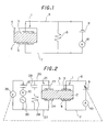
- Fig. 1 is a diagram showing a circuit illustrating an example of a basic structure according to the present invention.
- An electrochemical pump cell 1 is made up of a solid electrolyte partition 2 comprising such as a zirconia ceramic which shows substantially no ion conductivity at room temperature and shows ion conductivity at an elevated temperature, a pair of electrodes 3 and 4 formed on the inner surface and outer surface of the solid electrolyte partition 2, respectively, and a gas diffusion resistance layer 5 formed on the electrode 3.
- a -resistor 8 having a resistance corresponding to the sensitivity of the cell is connected to output terminals 6 and 7 of the electrochemical pump cell 1 in parallel therewith.
- Sensitivity of cell and offset value are examples of the characteristic values of electrochemical pump cell (electric signal characteristic of sensor in the case of including an electric signal conversion means as shown in Fig. 3 through Fig. 5, described later) represented by the electric characteristic value of an RLC element as a resistor in Fig. 1.
- the fixed resistor 8 may be configured with thermet as the resistor sintered onto the sensor element, or may be contained in the connector casing of the sensor.
- Fig. 2 is a circuit diagram illustrating another example of a basic structure according to the present invention. Similar with the basic structure of Fig. 1, an electrochemical pump cell 1 is made up of a solid electrolyte partition 2, a pair of electrodes 3 and 4 formed on the inner surface and outer surface thereof, respectively, and a gas diffusion resistance layer 5 formed on the electrode 3. A power source 9 and a current detection means 10 are arranged between output terminals 6 and 7 of the electrochemical pump cell 1.
- a further pair of electrodes 23 and 24 are provided, respectively, to form an electrochemical pump cell 21 combined with the gas diffusion layer 5 formed on the electrode 23.
- a fixed resistor 28 having a resistance corresponding to the sensitivity of the electrochemical pump cell 1 adjacent to the electrochemical pump cell 21 is connected to the output terminals 26 and 27 of the electrochemical pump cell 21 via a capacitor 29 in parallel with the cell.
- the resistance value is set to correspond to the sensitivity of the electrochemical pump cell 1
- correction is capable of effecting without influencing the current detection circuit of the electrochemical pump cell 1 and, even in the case of the electrochemical pump cell 21 for measuring an electromotive force, without influencing the electromotive force.
- a potential difference (voltage) detection means 35 conducts the measurement of electromotive force corresponding to the difference of oxygen concentration between the electrodes 23 and 24.
- the voltage applied to the electrochemical pump cell 1 is adjusted to control the electromotive force to a specific value.
- Fig. 3 shows a cross sectional view of major part of a NOx sensor provided with a heater section, and an electric circuit thereof.
- the NOx sensor include a first internal space 42 and a second internal space 44 which are arranged separately with each other while positioning the first internal space 42 at the front end of the sensor element.
- a reference gas introduction space 47 as a reference gas existing space extends in the longitudinal direction of the sensor element independently from the first internal space 42 and from the second internal space 44.
- a first diffusion controlled section 41 which connects the first internal space 42 with an external measuring gas exiting space is arranged at the tip of the sensor element.
- the first internal space 42 and the second internal space 44 are connected with each other by a second diffusion controlled section 43.
- the portion on a solid electrolyte partition 2 exposed to the first internal space 42 is provided with an inner pump electrode 13.
- An outer pump electrode 14 is formed on the outer surface of the solid electrolyte partition 2 at opposite site of the inner pump electrode 13.
- a main pump means (electrochemical pump cell) 1 is made up of these electrodes 13 and 14, and the solid electrolyte partition 2. Between an output terminals 6 and 7 of the main pump means 1, power source 9 and a current detection means 10 are arranged in the circuit, while connecting a fixed resistor 8 having a resistance value corresponding to the sensitivity of the main pump means 1 between the output terminals 6 and 7 in parallel.
- the measuring electrode 45 is formed on a portion of the solid electrolyte partition 2 exposing to the second internal space 44, and a reference electrode 46 is formed on a portion of the solid electrolyte partition 2 exposing to the reference gas introduction space 47.
- a measuring pump means 20 is made up of a measuring electrode 45, the reference electrode 46, and the solid electrolyte partition 2.
- the circuit is structured to have a power source 17 and a current detection means 18 between the output terminals of the measuring pump means 20.
- a heater section 40 is provided in the NOx sensor in such a manner that a heater 16 is buried while being surrounded by the solid electrolyte of the sensor.
- the heater generates heat by receiving power from a heater power source 48.
- the measuring gas passes through the first diffusion controlled section 41 to enter the first internal space 42.
- the diffusion limiting current value of oxygen is determined by the current detection means 10.
- the NO which is not decomposed in the internal space 42 passes through the second diffusion controlled section 43 to enter the second internal space 44.
- voltage from the power source 17 between the measuring electrode 45 and the reference electrode 46 NO is decomposed.
- the quantity of oxygen generated by the decomposition of NO is measured by a current detection means 18 to determine the quantity of NOx.
- the value of resistance of resistor 8 is set to a value corresponding to the sensitivity to oxygen in the first internal space 42, or to the sensitivity to NOx gas in the second internal space 44, the value of pump current flowing to the main pump means 1, or the value of current flowing to the measuring pump means 3 is able to be corrected using the correction factor derived based on the measured value of the resistance of the resistor 8 using the current detection mears 10 at room temperature.
- the main pump means 1 does not decompose NO, so that the current flowing into the resistor 8 is independent of NOx measurement.
- the correction of NOx sensitivity or of offset may be effected at high accuracy.
- Fig. 4 shows a cross sectional view of main part of another NOx sensor and the electric circuit thereof.
- the NOx sensor has only the first internal space 42 and does not have the second internal space 44. Instead of the second internal space 44, the second diffusion controlled section 43 made of gas diffusion resistance layer is formed. And further, as the measuring electrode 45, the one having a catalytic activity to decompose NOx gas is used.
- the inner pump electrode 13 is formed, whereas, at a portion of the solid electrolyte partition 2 exposing to the reference gas introduction space 47, the outer pump electrode 14 which is common with the reference electrode is formed.
- the main pump means 1 is structured by these electrodes 13 and 14, and the solid electrolyte partition 2.
- a circuit having the power source 9 is formed between the output terminals of the main pump means 1.
- the measuring electrode 45 which has a catalytic activity to decompose N0x gas is formed.
- the second diffusion controlled section 43 comprising a gas diffusion resistance layer is formed covering the measuring electrode 45.
- the reference electrode 14 which is common with the outer pump electrode is formed.
- the measuring pump means 1 is structured by the measuring electrode 45, the reference electrode 14, and the solid electrolyte partition 2.
- a circuit having the power source 17 and the current detection means 10 is formed between the output terminals of the measuring pump means, while the fixed resistor 8 is connected between the output terminals of the electrochemical sensor cell in parallel with the cell.
- the measuring gas passes through the first diffusion controlled section 41 to enter the first internal space 42.
- the pair of pump electrodes 13 and 14 formed on the inner surface and outer surface of the solid electrolyte partition 2 made of a zirconia ceramic, respectively, facing with each other a quantity of oxygen within the first internal space 42 is brought to near a zero level.
- the NOx gas which passes through the second diffusion controlled section 43 and arrives at the measuring electrode 45 having a catalytic activity is decomposed to generate oxygen.
- the quantity of oxygen is measured by the current detection means 10 to determine the quantity of NOx.
- the NOx sensitivity is capable of being corrected at a high accuracy by measuring the value of resistance of resistor 8 using the current detection means 10 at room temperature and by applying correction factor derived from the measured value of the resistance of resistor 8.
- Fig. 5 shows a cross sectional view of a main part of a diffusion limiting current type oxygen sensor and the electric circuit thereof.
- the inner pump electrode 13 is formed on a portion of the solid electrolyte partition 2 exposing to the internal space 52
- the outer pump electrode 14 is formed on the outer surface of the solid electrolyte partition 2 at a site opposite to the inner pump electrode 13.
- the main pump means 1 is structured by these electrodes 13 and 14, and the solid electrolyte partition 2.
- the measuring electrode 53 is formed at a different exposed portion in the internal space 52 of the solid electrolyte partition 2, the measuring electrode 53 is formed.
- the reference electrode 54 is formed.
- the oxygen concentration cell is structured by the measuring electrode 53, the reference electrode 54, and the solid electrolyte partition 2.
- a circuit having the power source 9 and the current detection means 10 is formed between the output terminals of the main pump means 1, while connecting a series circuit of an alternate current power source 70, a resistor 56, and a capacitor 71 between the output terminals of the oxygen concentration cell, and also connecting a series circuit of a resistor 68 and a capacitor 69 between the output terminals of the oxygen concentration cell in parallel therewith.
- the measuring gas passes through the diffusion controlled section 51 to enter the internal space 52.
- the pair of electrodes 13 and 14 formed on the inner surface and outer surface of the solid electrolyte partition 2 made of a zirconia ceramic, respectively, facing with eath other a quantity of oxygen within the internal space 52 is brought to a near zero level.
- the oxygen partial pressure in the internal space 52 is measured by a potential difference detection means 55 as the electromotive force which is determined by the ratio to the oxygen partial pressure in the reference gas introduction space 47 using the oxygen concentration cell structured by the electrodes 53 and 54 and by the solid electrolyte partition 2.
- the voltage of the power source 9 is controlled to match the determined electromotive force with the predetermined value.
- the current flowing across the current detection means 10 corresponds to the oxygen concentration in the measuring gas. If the value of the resistance of a resistor 68 is set to a value corresponding to the sensitivity to oxygen gas, then it is possible that the value of the resistance of resistor 68 is measured by the potential difference (voltage) detection means 55 as a divided voltage of the alternate current power source 70 using the resistors 56 and 68, and that the sensitivity of measurement is matched to the sensitivity of individual sensors.
- the impedance of capacitors 69 and 71 is assumed as sufficiently small.
- Fig. 6 shows a cross sectional view of main part of a sensor element provided with an auxiliary pump for further adjusting fine variation of oxygen partial pressure in the measuring gas which has been subjected to the adjustment of oxygen partial pressure in the main pump cell 1, and conducting measurement of N0x concentration by means of electromotive force.
- Fig. 6 also shows the electric circuit of the sensor element.
- the example of Fig. 6 has basically the same configuration of the main pump 1 and the heater section 40, and differs in that an auxiliary pump 80 is added, that the NOx concentration is measured by means of electromotive force generated in a concentration detection means 90 which comprises a detection electrode 82 and the reference electrode 46.
- a circuit is structured by locating the power source 9 between the output terminals 6 and 7 of the main pump means 1, while connecting the fixed resistor 8 having a resistance corresponding to the sensitivity of the concentration detection means 90 between the output terminals 6 and 7 in parallel with the power source.
- a portion of the solid electrolyte partition 2 exposed to the second internal space 44 is provided with the detection electrode 82.
- a portion of the solid electrolyte partition 2 exposed to the reference gas introduction space 47 is provided with the reference electrode 46.
- the concentration detection means 90 is structured by the detection electrode 82, the reference electrode 46, and the solid electrolyte partition 2.
- a different portion in the second internal space 44 is provided with the auxiliary pump electrode 80.
- the auxiliary pump means 84 is structured by the auxiliary pump electrode 80, the reference electrode 46 formed in the reference gas introduction space 47, and the solid electrolyte partition 2.
- a potential difference detection means 83 is arranged between the output terminals of the concentration detection means 90.
- a circuit having the power source 85 is formed between the output terminals of the auxiliary pump means 84, while connecting a fixed resistor 88 having a resistance corresponding to the offset value of the concentration detection means 90 in parallel therewith.
- the measuring gas passes through the first diffusion controlled section 41 to enter the first internal space 42.
- the oxygen pumping action is induced, which pumping action controls the oxygen partial pressure to a predetermined level at which NO does not decompose.
- the measuring gas in which the oxygen partial pressure is controlled to a predetermined level passes through the second diffusion controlled section 43 to enter the second internal space 44.
- the measuring gas is adjusted to further a low level of oxygen partial pressure.
- the NO is decomposed on the detection electrode 82 which has an ability of NO decomposition and which is formed in the second internal space 44.
- the NOx concentration is determined by determining the oxygen generated along with the decomposition of NO by means of the potential difference detection means 83.
- the measurement of resistance of the resistor 8 and of the resistor 88 by the current detection means 10 and by the current detection means 81, respectively, allows to set the correction factor to an optimum value to the sensor before actuating thereof. As a result, the NOx concentration is determined at higher accuracy.
- the description given above employed a configuration that an element has two electrochemical pump cells with two resistors. Nevertheless, the resistor may be other RLC element. In addition, the number of RLC elements is arbitrarily chosen responding to the number of pump cells.
Landscapes
- Chemical & Material Sciences (AREA)
- Life Sciences & Earth Sciences (AREA)
- Health & Medical Sciences (AREA)
- Physics & Mathematics (AREA)
- Chemical Kinetics & Catalysis (AREA)
- Electrochemistry (AREA)
- Molecular Biology (AREA)
- Analytical Chemistry (AREA)
- Biochemistry (AREA)
- General Health & Medical Sciences (AREA)
- General Physics & Mathematics (AREA)
- Immunology (AREA)
- Pathology (AREA)
- Measuring Oxygen Concentration In Cells (AREA)
Applications Claiming Priority (6)
| Application Number | Priority Date | Filing Date | Title |
|---|---|---|---|
| JP6775596 | 1996-03-25 | ||
| JP67755/96 | 1996-03-25 | ||
| JP6775596 | 1996-03-25 | ||
| JP4505097 | 1997-02-28 | ||
| JP9045050A JPH09318594A (ja) | 1996-03-25 | 1997-02-28 | ガスセンサおよび被測定ガス中の特定成分量の測定方法 |
| JP45050/97 | 1997-02-28 |
Publications (3)
| Publication Number | Publication Date |
|---|---|
| EP0798557A2 true EP0798557A2 (fr) | 1997-10-01 |
| EP0798557A3 EP0798557A3 (fr) | 1998-10-07 |
| EP0798557B1 EP0798557B1 (fr) | 2005-07-20 |
Family
ID=26385010
Family Applications (1)
| Application Number | Title | Priority Date | Filing Date |
|---|---|---|---|
| EP97302000A Expired - Lifetime EP0798557B1 (fr) | 1996-03-25 | 1997-03-24 | Capteur de gaz et méthode pour mesurer la quantité de composés spécifiques dans un gaz de mesure |
Country Status (4)
| Country | Link |
|---|---|
| US (1) | US5928494A (fr) |
| EP (1) | EP0798557B1 (fr) |
| JP (1) | JPH09318594A (fr) |
| DE (1) | DE69733728T2 (fr) |
Cited By (2)
| Publication number | Priority date | Publication date | Assignee | Title |
|---|---|---|---|---|
| EP0933631A3 (fr) * | 1998-01-28 | 2004-09-29 | Ngk Spark Plug Co., Ltd. | Connecteur pour un capteur de NOx |
| WO2007074021A1 (fr) * | 2005-12-23 | 2007-07-05 | Robert Bosch Gmbh | Sonde lambda a large bande |
Families Citing this family (18)
| Publication number | Priority date | Publication date | Assignee | Title |
|---|---|---|---|---|
| JP3544437B2 (ja) * | 1996-09-19 | 2004-07-21 | 日本碍子株式会社 | ガスセンサ |
| JP3332761B2 (ja) * | 1996-11-08 | 2002-10-07 | 日本特殊陶業株式会社 | 酸素濃度・窒素酸化物濃度測定方法及び装置 |
| JP3532366B2 (ja) * | 1996-11-18 | 2004-05-31 | 日本特殊陶業株式会社 | センサ用耐熱金属シースリード線 |
| US6623618B1 (en) | 1997-12-22 | 2003-09-23 | Ngk Insulators, Ltd. | Gas sensor and method for controlling the same |
| DE19804669A1 (de) | 1998-02-06 | 1999-08-12 | Bosch Gmbh Robert | Elektrisches Kontaktelement |
| DE19819581C2 (de) * | 1998-04-30 | 2002-08-08 | Siemens Ag | Verfahren zur Bestimmung der NO¶x¶-Konzentration |
| DE19819462A1 (de) * | 1998-04-30 | 1999-11-11 | Siemens Ag | Verfahren zur Bestimmung der NOx-Konzentration |
| JP4563601B2 (ja) * | 2000-03-31 | 2010-10-13 | 株式会社デンソー | 複合積層型センサ素子 |
| JP4313027B2 (ja) | 2002-11-12 | 2009-08-12 | 日本碍子株式会社 | ガスセンサ |
| JP3849678B2 (ja) * | 2003-09-19 | 2006-11-22 | トヨタ自動車株式会社 | ガス濃度測定装置 |
| JP4610965B2 (ja) * | 2004-08-11 | 2011-01-12 | 株式会社タニタ | 電気化学式測定装置 |
| US7611612B2 (en) * | 2005-07-14 | 2009-11-03 | Ceramatec, Inc. | Multilayer ceramic NOx gas sensor device |
| JP2010519514A (ja) * | 2007-02-16 | 2010-06-03 | セラマテック・インク | 選択性および検出感度の改善されたNOxセンサー |
| DE102007011049A1 (de) * | 2007-03-07 | 2008-09-11 | Robert Bosch Gmbh | Gassensor zur Messung einer Gaskomponente in einem Gasgemisch |
| US9164080B2 (en) | 2012-06-11 | 2015-10-20 | Ohio State Innovation Foundation | System and method for sensing NO |
| TWI676280B (zh) * | 2014-04-18 | 2019-11-01 | 日商新力股份有限公司 | 固體攝像裝置及具備其之電子機器 |
| US9964459B2 (en) | 2014-11-03 | 2018-05-08 | Quartzdyne, Inc. | Pass-throughs for use with sensor assemblies, sensor assemblies including at least one pass-through and related methods |
| JP7375784B2 (ja) | 2021-03-05 | 2023-11-08 | 横河電機株式会社 | 酸素濃度計、酸素濃度検出システム及びジルコニアセンサの抵抗検出方法 |
Family Cites Families (18)
| Publication number | Priority date | Publication date | Assignee | Title |
|---|---|---|---|---|
| DE3029446A1 (de) * | 1980-08-02 | 1982-03-11 | Robert Bosch Gmbh, 7000 Stuttgart | Duennschichtanordnung |
| JPS57192856A (en) * | 1981-05-25 | 1982-11-27 | Ngk Insulators Ltd | Oxygen concentration detector |
| JPS57200850A (en) * | 1981-06-04 | 1982-12-09 | Ngk Insulators Ltd | Detector for oxygen concentration |
| JPS57203940A (en) * | 1981-06-11 | 1982-12-14 | Nissan Motor Co Ltd | Gas sensor |
| US4634514A (en) * | 1985-02-14 | 1987-01-06 | Ngk Insulators, Ltd. | Electrochemical apparatus and method of manufacturing the same |
| US4875990A (en) * | 1986-08-28 | 1989-10-24 | Ngk Insulators, Ltd. | Oxygen concentration measuring device |
| US4963246A (en) * | 1987-12-14 | 1990-10-16 | Honda Giken Kogyo Kabushiki Kaisha | Oxygen concentration-sensing device |
| FR2636737B1 (fr) * | 1988-09-16 | 1993-12-03 | Thomson Csf | Capteur de type resistif, de mesure de concentrations relatives d'especes reactives fluides, compense en temperature |
| US5173166A (en) * | 1990-04-16 | 1992-12-22 | Minitech Co. | Electrochemical gas sensor cells |
| JP2880273B2 (ja) * | 1990-08-20 | 1999-04-05 | 株式会社日本自動車部品総合研究所 | 酸素濃度検出装置 |
| DE69006503T2 (de) * | 1990-09-13 | 1994-06-09 | Honeywell Bv | Verfahren und Messfühler zur Bestimmung von Sauerstoffpartialdruck. |
| JPH06507521A (ja) * | 1991-02-15 | 1994-08-25 | シーメンス アクチエンゲゼルシヤフト | 高温センサ技術のための高速白金族金属温度センサ用装置 |
| US5234569A (en) * | 1992-04-13 | 1993-08-10 | Hitachi America, Ltd., Research And Development Division | Air/fuel ratio sensor for an internal combustion engine |
| DE4304966A1 (de) * | 1993-02-18 | 1994-08-25 | Bosch Gmbh Robert | Lambdawert-Ermittlungsvorrichtung |
| JPH08507376A (ja) * | 1993-03-01 | 1996-08-06 | フォード モーター カンパニー | 電流複製回路および排気中の酸素モニタリング |
| US5397442A (en) * | 1994-03-09 | 1995-03-14 | Gas Research Institute | Sensor and method for accurately measuring concentrations of oxide compounds in gas mixtures |
| JP2885336B2 (ja) * | 1994-04-21 | 1999-04-19 | 日本碍子株式会社 | 被測定ガス中のNOx濃度の測定方法及び測定装置 |
| DE19539357B4 (de) * | 1994-10-24 | 2011-09-15 | Denso Corporation | Luft-Brennstoffverhältnis-Erfassungseinrichtung |
-
1997
- 1997-02-28 JP JP9045050A patent/JPH09318594A/ja active Pending
- 1997-03-14 US US08/818,715 patent/US5928494A/en not_active Expired - Lifetime
- 1997-03-24 EP EP97302000A patent/EP0798557B1/fr not_active Expired - Lifetime
- 1997-03-24 DE DE69733728T patent/DE69733728T2/de not_active Expired - Lifetime
Cited By (2)
| Publication number | Priority date | Publication date | Assignee | Title |
|---|---|---|---|---|
| EP0933631A3 (fr) * | 1998-01-28 | 2004-09-29 | Ngk Spark Plug Co., Ltd. | Connecteur pour un capteur de NOx |
| WO2007074021A1 (fr) * | 2005-12-23 | 2007-07-05 | Robert Bosch Gmbh | Sonde lambda a large bande |
Also Published As
| Publication number | Publication date |
|---|---|
| DE69733728D1 (de) | 2005-08-25 |
| US5928494A (en) | 1999-07-27 |
| EP0798557A3 (fr) | 1998-10-07 |
| JPH09318594A (ja) | 1997-12-12 |
| EP0798557B1 (fr) | 2005-07-20 |
| DE69733728T2 (de) | 2006-04-20 |
Similar Documents
| Publication | Publication Date | Title |
|---|---|---|
| EP0798557A2 (fr) | Capteur de gaz et méthode pour mesurer la quantité de composés spécifiques dans un gaz de mesure | |
| EP0807818B1 (fr) | Procédé de détermination d'oxide d'azote | |
| EP0862056B1 (fr) | Capteur de gaz | |
| EP0878709B1 (fr) | Procédé et appareil de mesure de la concentration d'oxydes d'azote | |
| EP1890139B1 (fr) | Système de capteur de NOx avec unité de circuit de commande | |
| US8052863B2 (en) | Gas sensor control apparatus designed to ensure accuracy of measurement in gas sensor | |
| US4722779A (en) | Air/fuel ratio sensor | |
| US6592731B1 (en) | Amperometric oxygen sensor | |
| EP0152293A2 (fr) | Capteur du rapport air/combustible d'un moteur | |
| KR102090938B1 (ko) | 펌프 셀을 포함하는 고체 전해질 센서 소자의 작동 방법 | |
| US7655131B2 (en) | Gas sensor and method for controlling the same | |
| US7445698B2 (en) | Gas concentration detecting apparatus | |
| EP2056099A1 (fr) | Dispositif de contrôle du capteur | |
| EP0933631B1 (fr) | Capteur de NOx | |
| US4426621A (en) | Detection circuitry for electrochemical analysis | |
| JPS634660B2 (fr) | ||
| RU2171468C1 (ru) | Способ анализа состава газовых смесей и газоанализатор для его реализации | |
| US6312585B1 (en) | Method for determining oxidizable constituents in a gaseous mixture | |
| EP0863399B1 (fr) | Capteur de gaz et procédé pour le contrôler | |
| US20060011476A1 (en) | Gas concentration measuring apparatus designed to ensuring accuracy of determining resistance of gas sensor element | |
| EP0924514B1 (fr) | Captuer de gaz et méthode pour le contrôler | |
| US4321113A (en) | Electronic calibration of electrochemical sensors | |
| EP0083968B1 (fr) | Polarographie | |
| JP3544981B2 (ja) | 酸素測定センサ | |
| EP0067437A1 (fr) | Senseur d'oxygène et méthode d'utilisation |
Legal Events
| Date | Code | Title | Description |
|---|---|---|---|
| PUAI | Public reference made under article 153(3) epc to a published international application that has entered the european phase |
Free format text: ORIGINAL CODE: 0009012 |
|
| AK | Designated contracting states |
Kind code of ref document: A2 Designated state(s): DE FR GB IT SE |
|
| PUAL | Search report despatched |
Free format text: ORIGINAL CODE: 0009013 |
|
| AK | Designated contracting states |
Kind code of ref document: A3 Designated state(s): DE FR GB IT SE |
|
| 17P | Request for examination filed |
Effective date: 19981104 |
|
| 17Q | First examination report despatched |
Effective date: 20021127 |
|
| GRAP | Despatch of communication of intention to grant a patent |
Free format text: ORIGINAL CODE: EPIDOSNIGR1 |
|
| GRAS | Grant fee paid |
Free format text: ORIGINAL CODE: EPIDOSNIGR3 |
|
| GRAA | (expected) grant |
Free format text: ORIGINAL CODE: 0009210 |
|
| AK | Designated contracting states |
Kind code of ref document: B1 Designated state(s): DE FR GB IT SE |
|
| PG25 | Lapsed in a contracting state [announced via postgrant information from national office to epo] |
Ref country code: IT Free format text: LAPSE BECAUSE OF FAILURE TO SUBMIT A TRANSLATION OF THE DESCRIPTION OR TO PAY THE FEE WITHIN THE PRESCRIBED TIME-LIMIT;WARNING: LAPSES OF ITALIAN PATENTS WITH EFFECTIVE DATE BEFORE 2007 MAY HAVE OCCURRED AT ANY TIME BEFORE 2007. THE CORRECT EFFECTIVE DATE MAY BE DIFFERENT FROM THE ONE RECORDED. Effective date: 20050720 |
|
| REG | Reference to a national code |
Ref country code: GB Ref legal event code: FG4D |
|
| REF | Corresponds to: |
Ref document number: 69733728 Country of ref document: DE Date of ref document: 20050825 Kind code of ref document: P |
|
| PG25 | Lapsed in a contracting state [announced via postgrant information from national office to epo] |
Ref country code: SE Free format text: LAPSE BECAUSE OF FAILURE TO SUBMIT A TRANSLATION OF THE DESCRIPTION OR TO PAY THE FEE WITHIN THE PRESCRIBED TIME-LIMIT Effective date: 20051020 |
|
| PG25 | Lapsed in a contracting state [announced via postgrant information from national office to epo] |
Ref country code: GB Free format text: LAPSE BECAUSE OF NON-PAYMENT OF DUE FEES Effective date: 20060324 |
|
| PLBE | No opposition filed within time limit |
Free format text: ORIGINAL CODE: 0009261 |
|
| STAA | Information on the status of an ep patent application or granted ep patent |
Free format text: STATUS: NO OPPOSITION FILED WITHIN TIME LIMIT |
|
| 26N | No opposition filed |
Effective date: 20060421 |
|
| EN | Fr: translation not filed | ||
| PG25 | Lapsed in a contracting state [announced via postgrant information from national office to epo] |
Ref country code: FR Free format text: LAPSE BECAUSE OF FAILURE TO SUBMIT A TRANSLATION OF THE DESCRIPTION OR TO PAY THE FEE WITHIN THE PRESCRIBED TIME-LIMIT Effective date: 20060915 |
|
| GBPC | Gb: european patent ceased through non-payment of renewal fee |
Effective date: 20060324 |
|
| PG25 | Lapsed in a contracting state [announced via postgrant information from national office to epo] |
Ref country code: FR Free format text: LAPSE BECAUSE OF FAILURE TO SUBMIT A TRANSLATION OF THE DESCRIPTION OR TO PAY THE FEE WITHIN THE PRESCRIBED TIME-LIMIT Effective date: 20050720 |
|
| PGFP | Annual fee paid to national office [announced via postgrant information from national office to epo] |
Ref country code: DE Payment date: 20160315 Year of fee payment: 20 |
|
| REG | Reference to a national code |
Ref country code: DE Ref legal event code: R071 Ref document number: 69733728 Country of ref document: DE |