EP0798711A2 - Platte zur Informationsaufzeichnung mit Verwaltungszonen - Google Patents
Platte zur Informationsaufzeichnung mit Verwaltungszonen Download PDFInfo
- Publication number
- EP0798711A2 EP0798711A2 EP97105050A EP97105050A EP0798711A2 EP 0798711 A2 EP0798711 A2 EP 0798711A2 EP 97105050 A EP97105050 A EP 97105050A EP 97105050 A EP97105050 A EP 97105050A EP 0798711 A2 EP0798711 A2 EP 0798711A2
- Authority
- EP
- European Patent Office
- Prior art keywords
- disk
- data
- management
- area
- rotation
- Prior art date
- Legal status (The legal status is an assumption and is not a legal conclusion. Google has not performed a legal analysis and makes no representation as to the accuracy of the status listed.)
- Granted
Links
Images


Classifications
-
- G—PHYSICS
- G11—INFORMATION STORAGE
- G11B—INFORMATION STORAGE BASED ON RELATIVE MOVEMENT BETWEEN RECORD CARRIER AND TRANSDUCER
- G11B7/00—Recording or reproducing by optical means, e.g. recording using a thermal beam of optical radiation by modifying optical properties or the physical structure, reproducing using an optical beam at lower power by sensing optical properties; Record carriers therefor
- G11B7/007—Arrangement of the information on the record carrier, e.g. form of tracks, actual track shape, e.g. wobbled, or cross-section, e.g. v-shaped; Sequential information structures, e.g. sectoring or header formats within a track
- G11B7/0079—Zoned data area, e.g. having different data structures or formats for the user data within data layer, Zone Constant Linear Velocity [ZCLV], Zone Constant Angular Velocity [ZCAV], carriers with RAM and ROM areas
-
- G—PHYSICS
- G11—INFORMATION STORAGE
- G11B—INFORMATION STORAGE BASED ON RELATIVE MOVEMENT BETWEEN RECORD CARRIER AND TRANSDUCER
- G11B20/00—Signal processing not specific to the method of recording or reproducing; Circuits therefor
- G11B20/10—Digital recording or reproducing
- G11B20/18—Error detection or correction; Testing, e.g. of drop-outs
- G11B20/1883—Methods for assignment of alternate areas for defective areas
-
- G—PHYSICS
- G11—INFORMATION STORAGE
- G11B—INFORMATION STORAGE BASED ON RELATIVE MOVEMENT BETWEEN RECORD CARRIER AND TRANSDUCER
- G11B20/00—Signal processing not specific to the method of recording or reproducing; Circuits therefor
- G11B20/10—Digital recording or reproducing
- G11B20/12—Formatting, e.g. arrangement of data block or words on the record carriers
- G11B20/1217—Formatting, e.g. arrangement of data block or words on the record carriers on discs
- G11B20/1258—Formatting, e.g. arrangement of data block or words on the record carriers on discs where blocks are arranged within multiple radial zones, e.g. Zone Bit Recording or Constant Density Recording discs, MCAV discs, MCLV discs
-
- G—PHYSICS
- G11—INFORMATION STORAGE
- G11B—INFORMATION STORAGE BASED ON RELATIVE MOVEMENT BETWEEN RECORD CARRIER AND TRANSDUCER
- G11B27/00—Editing; Indexing; Addressing; Timing or synchronising; Monitoring; Measuring tape travel
- G11B27/10—Indexing; Addressing; Timing or synchronising; Measuring tape travel
- G11B27/19—Indexing; Addressing; Timing or synchronising; Measuring tape travel by using information detectable on the record carrier
- G11B27/28—Indexing; Addressing; Timing or synchronising; Measuring tape travel by using information detectable on the record carrier by using information signals recorded by the same method as the main recording
- G11B27/32—Indexing; Addressing; Timing or synchronising; Measuring tape travel by using information detectable on the record carrier by using information signals recorded by the same method as the main recording on separate auxiliary tracks of the same or an auxiliary record carrier
- G11B27/327—Table of contents
- G11B27/329—Table of contents on a disc [VTOC]
-
- G—PHYSICS
- G11—INFORMATION STORAGE
- G11B—INFORMATION STORAGE BASED ON RELATIVE MOVEMENT BETWEEN RECORD CARRIER AND TRANSDUCER
- G11B7/00—Recording or reproducing by optical means, e.g. recording using a thermal beam of optical radiation by modifying optical properties or the physical structure, reproducing using an optical beam at lower power by sensing optical properties; Record carriers therefor
- G11B7/004—Recording, reproducing or erasing methods; Read, write or erase circuits therefor
- G11B7/0045—Recording
-
- G—PHYSICS
- G11—INFORMATION STORAGE
- G11B—INFORMATION STORAGE BASED ON RELATIVE MOVEMENT BETWEEN RECORD CARRIER AND TRANSDUCER
- G11B2220/00—Record carriers by type
- G11B2220/20—Disc-shaped record carriers
-
- G—PHYSICS
- G11—INFORMATION STORAGE
- G11B—INFORMATION STORAGE BASED ON RELATIVE MOVEMENT BETWEEN RECORD CARRIER AND TRANSDUCER
- G11B2220/00—Record carriers by type
- G11B2220/20—Disc-shaped record carriers
- G11B2220/23—Disc-shaped record carriers characterised in that the disc has a specific layer structure
- G11B2220/235—Multilayer discs, i.e. multiple recording layers accessed from the same side
- G11B2220/237—Multilayer discs, i.e. multiple recording layers accessed from the same side having exactly two recording layers
-
- G—PHYSICS
- G11—INFORMATION STORAGE
- G11B—INFORMATION STORAGE BASED ON RELATIVE MOVEMENT BETWEEN RECORD CARRIER AND TRANSDUCER
- G11B2220/00—Record carriers by type
- G11B2220/20—Disc-shaped record carriers
- G11B2220/25—Disc-shaped record carriers characterised in that the disc is based on a specific recording technology
- G11B2220/2537—Optical discs
- G11B2220/2562—DVDs [digital versatile discs]; Digital video discs; MMCDs; HDCDs
-
- G—PHYSICS
- G11—INFORMATION STORAGE
- G11B—INFORMATION STORAGE BASED ON RELATIVE MOVEMENT BETWEEN RECORD CARRIER AND TRANSDUCER
- G11B7/00—Recording or reproducing by optical means, e.g. recording using a thermal beam of optical radiation by modifying optical properties or the physical structure, reproducing using an optical beam at lower power by sensing optical properties; Record carriers therefor
- G11B7/24—Record carriers characterised by shape, structure or physical properties, or by the selection of the material
Definitions
- the present invention relates to a recording information management method for a disk of a zone CLV (every time the recording track zone changes, the angular velocity changes; the angular velocity does not change in a zone) or a modified CAV (the angular velocity changes stepwise depending on the recording track position; the angular velocity does not change in each step) type.
- zone CLV (to be referred to as ZCLV hereinafter; CLV is the abbreviation of Constant Linear Velocity)
- CAV Constant Angular Velocity
- the rotation speed changes so that the average recording density in each zone becomes almost constant. That is, in ZCLV, CAV control is performed in each zone, and when the zone changes, the angular velocity changes accordingly.
- zone CAV ZCAV
- MCAV modified CAV
- the rotation servo of the disk need not be switched in each zone because the angular velocity does not change in each zone so that access properties similar to those of a CAV disk can be obtained in each zone.
- the angular velocity is changed (reduced in the outer zone of the disk). With this operation, a decrease in recording density on the outer side of the disk is prevented by maintaining a roughly constant average linear velocity on both inner and outer sides of the disk. Therefore, in the ZCLV disk, a memory capacity similar to that of a CLV disk (within the same zone) and access properties similar to those of a CAV disk can be obtained.
- All writable disks of the CLV, CAV, and ZCLV schema require management information representing the size and position of a file recorded in the disk.
- This management information is generally called a file allocation table (FAT) and a set of pieces of management information are recorded in a specific area (one or two areas; in case of two areas, one area is used as a backup area) of the disk.
- FAT file allocation table
- the FAT is appropriately referred to when data is to be read out from or written in the disk.
- the disk rotation speed is always constant.
- the rotation servo of the disk need not be switched (the rotation speed of a spindle motor need not be changed) even when the FAT reference operation is frequently performed in data reading/writing, and reading/writing is smoothly performed.
- the disk rotation speed of the data read/write area is different from that of the FAT area. For this reason, the rotation speed of the spindle motor must be changed every time the FAT is referred to, and the read/write access speed decreases (since the rotation servo is switched every time the optical pickup reciprocates between constant rotation speed zones, the time lag until the servo is settled to a target rotation value is generated every time the zone changes).
- a file management area is formed for each constant rotation speed zone (in each constant angular velocity zone).
- an information recording disk which is rotated at one of a plurality of rotation speeds (N1 - N4) to record information comprises:
- write information management (ST36) for the first data area (DA1) is performed only in the first management area (MA1)
- write information management (ST36) for the second data area (DA2) is performed only in the second management area (MA2).
- an information recording disk which is rotated at one of a plurality of rotation speeds (N1 - N4) to record information, comprises:
- write information management (ST36) for the first data area (DA1) is performed only in the first management area (MA1)
- write information management (ST36) for the second data area (DA2) is performed only in the second management area (MA2).
- FIGS. 1 to 8 are views for explaining the information recording disk according to an embodiment of the present invention.
- FIGS. 9 to 11 are views for explaining the information management method for the information recording disk according to the embodiment of the present invention.
- FIGS. 12 to 41 are views for explaining the format of the information recording disk according to the embodiment of the present invention.
- FIG. 1 is a plan view showing double-layered optical disk OD used as an example of the pasted double-layered information recording medium of the present invention when viewed from a read laser reception face side.
- Optical disk OD has an outer diameter of 120 mm and central hole 70 with an inner diameter of 15 mm.
- Optical disk OD has a thickness of 1.2 mm corresponding to two 0.6-mm thick substrates which are pasted.
- Each of the pasted substrates has a doughnut-shaped information recording layer (data areas and replacement/management areas to be described later) (FIG. 1 shows only first information recording layer 10 on one substrate).
- the inner diameter of the doughnut-shaped information recording layer is about 45 mm, and the outer diameter is about 117 mm at maximum.
- FIG. 2 illustrates an enlarged view of part of the section of double-layered optical disk OD shown in FIG. 1 taken along a line (II) - (II).
- disk OD comprises polycarbonate substrate 30 (thickness: about 0.6 mm) for holding the first information recording layer, first information recording layer 10 (semi-transparent film having a thickness of about 10 to 1,000 nm) in which first information (upper face information of disk OD) formed by embossed pits is recorded, adhesive layer 50 (e.g., a UV curing resin) transparent to laser light RL, second information recording layer 20 (light-reflection film having a thickness of about 100 nm) in which second information (lower face information of optical disk OD) formed by embossed pits is recorded, and polycarbonate substrate 40 for holding the second information, viewed from a face on which read laser light RL (e.g., a semiconductor laser beam having a wavelength of 650 nm) is incident.
- read laser light RL e.g
- a label on which information (visual pattern information including characters, pictures, and patterns) associated with the recording information (the above-described first information and second information) is printed is bonded onto substrate face 40 on the opposite side of light reception face 30 of read laser light RL, as needed.
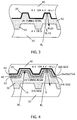
- FIG. 3 is a partial sectional view illustrating the data recording portion (embossed pits) of the double-layered optical disk (read only) shown in FIG. 1.
- a very thin metal film (thickness: about 10 to 20 nm) or a silicon (Si) thin film (thickness: about 10 to 1,000 nm) having a refractive index n of about 4 is used as first information recording layer 10.
- Information recording layer 10 may be formed of another semi-transparent metal film or another semi-transparent inorganic dielectric film having a refractive index higher than that of polycarbonate substrate 30D, i.e., 1.6 (e.g., an Si 3 N 4 thin film having a refractive index of about 2.0).
- the reason why the refractive index of information recording layer (semi-transparent inorganic dielectric film) 10 is made higher than that of substrate 30 is that laser light RL focused and incident in layer 10 need be reflected by an interface (a plane at which the refractive index abruptly changes) between layer 10 and substrate 30 (if the refractive index of layer 10 is equal to that of substrate 30, layer 10 and substrate 30 are formed of an optically uniform material with respect to laser light RL, so reflection of laser light does not occur at the interface between layer 10 and substrate 30. Reflected light RL10 from layer 10 is almost eliminated, so the first information recorded in layer 10 cannot be read).
- information recording layer 10 is a metal film such as a gold film
- the refractive index need not be taken into consideration, although thickness management for the layer is important (if layer 10 is too thick, light reflected by second information recording layer 20 is largely shielded by layer 10, lowering the read C/N ratio of layer 20; if layer 10 is too thin, light reflected by information recording layer 10 is weakened, lowering the read C/N ratio).
- FIG. 4 is a partial sectional view illustrating the data recording portion of read/write pasted double-layered optical disk OD in FIG. 1.
- Information recording layer 10 having a thickness of, e.g., 20 nm is formed of, instead of silicon shown in FIG. 3, a mixture (ZnS/SiO 2 ) of zinc sulfide (ZnS) and silicon oxide (SiO 2 ).
- a triple layer (90 to 94) consisting of two ZnS/SiO 2 mixture layers (92 and 94) with phase change recording material layer 90 (Ge 2 Sb 2 Te 5 ) sandwiched therebetween is formed between reflection layer 20 using aluminum (Al) or aluminum-molybdenum alloy (Al-Mo) and UV curing resin adhesive layer 50.
- the thickness of aluminum reflection film 20 is selected to be, e.g., about 100 nm.
- the thickness of ZnS/SiO 2 mixture layer 94 is selected to be, e.g., about 20 nm.
- the thickness of Ge 2 Sb 2 Te 5 phase change recording material layer 90 is selected to be, e.g., about 20 nm.
- the thickness of ZnS/SiO 2 mixture layer 92 is selected to be, about 180 nm.
- the read only information is recorded as an embossed pit signal in substrate 30. However, no embossed pit signal is recorded in substrate 40 of the read/write disk. Instead, a continuous groove is formed in substrate 40. Phase change recording material layer 90 is formed in this groove.
- a data area to be described later is formed on layer 10 or 20 shown in FIG. 3 or on layer 10 or 90 shown in FIG. 4.
- a replacement/management area to be described later is formed on layer 90 shown in FIG. 4.
- the present invention cannot be practiced with only the structure shown in FIG. 3.
- the present invention can be applied to an optical disk which has both the structures shown in FIGS. 3 and 4 (e.g., an optical disk having the structure in FIG. 3 at part of the inner side and the structure in FIG. 4 at part of the outer side).
- FIG. 5 is a view for explaining data track arrangement 1 (a replacement/management area is arranged inside each data area) of the double-layered optical disk shown in FIG. 4.
- replacement/management area MA1 whose rotation speed (rpm) is N1 is arranged spirally or concentrically with data area DA1 whose rotation speed is N1.
- Replacement/management area MA1 can be arranged at any portion in the zone where the rotation speed is equal to that of the data area DA1. In this case, replacement/management area MA1 is arranged on the inner side of disk OD.
- data area DA2 with rotation speed N2 is arranged outside data area DA1
- replacement/management area MA2 with rotation speed N2 is arranged spirally or concentrically with data area DA2.
- Data area DA3 with rotation speed N3 is arranged outside data area DA2, and replacement/management area MA3 with rotation speed N3 is arranged spirally or concentrically with data area DA3.
- Data area DA4 with rotation speed N4 is arranged outside data area DA3, and replacement/management area MA4 with rotation speed N4 is arranged spirally or concentrically with data area DA4.
- the relation between the rotation speeds of the constant rotation zones is defined as N1 > N2 > N3 > N4 to average the recording densities of the rotation zones (DA1 + MA1; DA2 + MA2; DA3 + MA3; DA4 + MA4), thereby ensuring a large recording capacity in the entire disk.
- the number of data areas or replacement/management areas (the number of zones with constant rotation speeds) is set to four for the descriptive convenience. However, the number of areas (the number of zones) may be larger in an actual disk, or the present invention can be practiced even with three or less zones.
- management (management of the data write range in the data area DA1) is performed only in replacement/management area MA1 of the same rotation speed zone.
- write management in data area DA2 is performed only in replacement/management area MA2 of the same rotation speed zone.
- write management in data area DA3 is performed only in replacement/management area MA3 of the same rotation speed zone.
- Write management in data area DA4 is performed only in replacement/management area MA4 of the same rotation speed zone.
- management management of the data read range in the data area DA1
- read management in data area DA2 is performed referring to only replacement/management area MA2 of the same rotation speed zone.
- Read management in data area DA3 is performed referring to only replacement/management area MA3 of the same rotation speed zone.
- Read management in data area DA4 is performed referring to only replacement/management area MA4 of the same rotation speed zone.
- FIG. 6 is a view for explaining data track arrangement 2 (a replacement/management area is arranged outside each data area) of the double-layered optical disk shown in FIG. 4.
- replacement/management area MA1 whose rotation speed (rpm) is N1 is arranged spirally or concentrically with data area DA1 whose rotation speed is N1. In this case, replacement/management area MA1 is arranged on the outer side of the same rotation speed zone.
- replacement/management area MA1 with rotation speed N1 is arranged, outside data area DA1 with rotation speed N1, spirally or concentrically with data area DA1.
- Data area DA2 with rotation speed N2 and replacement/management area MA2 with rotation speed N2 arranged spirally or concentrically with data area DA2 are formed outside replacement/management area MA1.
- Data area DA3 with rotation speed N3 and replacement/management area MA3 with rotation speed N3 arranged spirally or concentrically with data area DA3 are formed outside replacement/management area MA2.
- Data area DA4 with rotation speed N4 and replacement/management area MA4 with rotation speed N4 arranged spirally or concentrically with data area DA4 are formed outside replacement/management area MA3.
- the relation between the rotation speeds of the constant rotation zones is defined as N1 > N2 > N3 > N4 to average the recording densities of the rotation zones (DA1 + MA1; DA2 + MA2; DA3 + MA3; DA4 + MA4), thereby ensuring a large recording capacity in the entire disk.
- the number of data areas or replacement/management areas (the number of zones with constant rotation speeds) is set to four for the descriptive convenience. However, the number of areas (the number of zones) may be larger, or the present invention can be practiced even with three or less zones.
- management (management of the data write range in the data area DA1) is performed only in replacement/management area MA1 of the same rotation speed zone.
- write management in data area DA2 is performed only in replacement/management area MA2 of the same rotation speed zone.
- write management in data area DA3 is performed only in replacement/management area MA3 of the same rotation speed zone.
- Write management in data area DA4 is performed only in replacement/management area MA4 of the same rotation speed zone.
- management management of the data read range in the data area DA1
- read management in data area DA2 is performed referring to only replacement/management area MA2 of the same rotation speed zone.
- Read management in data area DA3 is performed referring to only replacement/management area MA3 of the same rotation speed zone.
- Read management in data area DA4 is performed referring to only replacement/management area MA4 of the same rotation speed zone.
- FIG. 7 is a view for explaining data track arrangement 3 (a replacement/management area is arranged at an intermediate position of each data area) of the double-layered optical disk shown in FIG. 4.
- replacement/management area MA1 whose rotation speed (rpm) is N1 is arranged spirally or concentrically with data area DA1 whose rotation speed is N1. In this case, replacement/management area MA1 is arranged at an intermediate position (optional position) of the same rotation speed zone.
- replacement/management area MA1 with rotation speed N1 is arranged, at an intermediate position of data area DA1 with rotation speed N1, spirally or concentrically with data area DA1.
- Data area DA2 with rotation speed N2 and replacement/management area MA2 with rotation speed N2 arranged spirally or concentrically with data area DA2 are formed outside data area DA1 on the outer side.
- Replacement/management area MA2 is arranged at an intermediate position of data area DA2.
- the relation between the rotation speeds of the constant rotation zones is defined as N1 > N2 to average the recording densities of the rotation zones (DA1 + MA1; DA2 + MA2), thereby ensuring a large recording capacity in the entire disk.
- the number of data areas or replacement/management areas (the number of zones with constant rotation speeds) is set to two for the descriptive convenience. However, the number of areas (the number of zones) may be larger.
- management management of the data write range in the data area DA1
- write management in data area DA2 is performed only in replacement/management area MA2 of the same rotation speed zone.
- management management of the data read range in the data area DA1
- read management in data area DA2 is performed referring to only replacement/management area MA2 of the same rotation speed zone.
- Optical disk OD having an area pattern shown in FIG. 6 or 7 has no replacement/management area MA1 between the lead-in area and first data area DA1.
- a disk reproducing apparatus (not shown) reads various disk content information from the lead-in area, data area DA1 can be immediately reproduced (the optical pickup need not jump replacement/management area MA). This is the large difference to the area pattern shown in FIG. 5.
- data areas DA1 and DA3 may have the read only structure in FIG. 3, and data areas DA2 and DA4 may have the read/write structure in FIG. 4.
- replacement areas MA1 and MA2 may be arranged in the rotation speed N2 zone and used for replacement/management processing of data area DA2
- replacement areas MA3 and MA4 may be arranged in the rotation speed N4 zone and used for replacement/management processing of data area DA4.
- FIG. 8 is a view for explaining the arrangement of data areas (DA1 to DA4) and replacement/management areas (MA1 to MA4) in units of track groups with the disk rotation speeds (N1 to N4) in an optical disk having the data track arrangement shown in FIG. 5 or 6.
- each constant rotation zone comprises 100 tracks (#001 to #100; #101 to #200; #201 to #300; #301 to #400).
- an arrangement shown in record map (1) of FIG. 8 is employed. More specifically, tracks with smaller numbers (#001 and #002 in the rotation speed N1 zone; #101 and #102 in the rotation speed N2 zone; #201 and #202 in the rotation speed N3 zone; #301 and #302 in the rotation speed N4 zone) are assigned to the replacement/management areas (MA1; MA2; MA3; MA4). Tracks with larger numbers (#003 to #100 in the rotation speed N1 zone; #103 to #200 in the rotation speed N2 zone; #203 to #300 in the rotation speed N3 zone; #303 to #400 in the rotation speed N4 zone) are assigned to the data areas (DA1; DA2; DA3; DA4).
- an arrangement shown in record map (2) of FIG. 8 is employed. More specifically, tracks with smaller numbers (#001 to #098 in the rotation speed N1 zone; #101 and #198 in the rotation speed N2 zone; #201 to #298 in the rotation speed N3 zone; #301 to #398 in the rotation speed N4 zone) are assigned to the data areas (DA1; DA2; DA3; DA4). Tracks with larger numbers (#099 and #100 in the rotation speed N1 zone; #199 and #200 in the rotation speed N2 zone; #299 and #300 in the rotation speed N3 zone; #399 and #400 in the rotation speed N4 zone) are assigned to the replacement/management areas (MA1; MA2; MA3; MA4).
- tracks #001 to #100 and tracks #111 to #200 may be assigned to data area DA1
- tracks #101 to #110 may be assigned to replacement/management area MA1.
- Tracks #201 to #300 and tracks #311 to #400 may be assigned to data area DA2, and tracks #301 to #310 may be assigned to replacement/management area MA2.
- the management area of a replacement/management area (MA1; MA2; MA3; MA4) is used for file system management of data recorded in the optical disk OD, recording/reproducing condition management of the data, and the like.
- the contents of file system management and recording/reproducing condition management are read out from the disk OD, and then stored in the memory of the host computer and managed by the host computer.
- the configuration of the file system depends on operating system OS of the host computer.
- the recording/reproducing conditions also depend on disk OD. Therefore, it is preferable to store the internal structure of disk OD in the memory of the host computer.
- recording/reproducing conditions can be managed in the following manner.
- Information associated with all the RAM, ROM, and R zones are recorded in the management area of disk OD at once, and necessary processing is performed on the basis of the information. The following operation can be considered for disk OD having such a management area.
- Defect information of the ROM and R zones are recorded in the management area of disk OD as defect information of the RAM zone.
- a ROM or R zone portion where the read precision degrades due to, e.g., flaws in disk OD to almost the error correction limit can be replaced with a RAM zone portion.
- Systematic management in a partial disk having the RAM, ROM, and R zones can be performed in the following fashion.
- the RAM zone portion can take charge of all processing such as replacement, use frequency management, and use condition management.
- a ROM zone portion frequently used by the user of disk OD is stored in the memory (RAM) of the host computer.
- the host computer uses the stored information (as if it were a disk cache) to increase the access speed to the frequently used information in disk OD.
- a password is set for information recorded in the ROM zone, and access to the information is disabled without the password.
- application distribution of the following form is enabled.
- Charged application software is stored in the ROM zone of disk OD.
- a charged password key information
- the password information of the application whose use is permitted is stored in the RAM zone.
- FIG. 9 is a flow chart for explaining writing in the optical disk having the data track arrangement shown in FIG. 5 or 6 (The disk write apparatus can have a known arrangement and therefore is not illustrated. The processing of this flow chart can be executed by the system software or firmware of the disk write apparatus).
- optical disk OD shown in FIG. 6 is Loaded in the disk write apparatus (not shown), and the user instructs data write access in any one of the data blocks of data area DA1.
- the system software or firmware detects the data size of a file to be written (step ST30). When the write data size is detected, it is checked in all data areas (DA1 to DA4) whether there is a free space corresponding to the write data size (step ST32). If no free space exists, i.e., if the data size of the write file is larger than the actual free space (NO in step ST34), an error message is output (step ST46), and writing is ended.
- step ST34 If a free space exists (YES in step ST34), the file code of the write data and write start and stop block numbers are recorded at the management area (MA2) with the same rotation speed (N2) as the data area (e.g., DA2) having the free space (step ST36).
- the data to be written in the management area may be a file code, a write start block number, and a file Length (number of blocks to be used).
- the free space is distributed in a plurality of data areas. For example, when data area DA1 has a free space of 900 kbytes, data area DA2 has no free space, data area DA3 has a free space of 1,600 kbytes, and data of 2,000 kbytes is to be written in this disk OD, management is performed in the following manner.
- the system software or firmware of the write apparatus writes the first 900-kbyte data of the write data in the free space (900 kbytes) of data area DA1, and the remaining data of 1,100 kbytes of the write data in the free space (1,600 kbytes) of data area DA3.
- file code (1) of the write data and the write start and stop block numbers of the first 900-kbyte data of the write data are recorded in management area MA1.
- File code (2) of the write data and the write start and stop block numbers of the remaining 1,100-kbyte data of the write data are recorded in management area MA3.
- data area DA1 has a free space of 900 kbytes
- data area DA2 has no free area
- data area DA3 has a free space of 2,200 kbytes
- the data having a file size of 2,000 kbytes is not divided to data areas DA1 and DA3 but written in the free space (2,200 kbytes) of data area DA3.
- the management data (file code and write start and stop block numbers) is written only in management area MA3.
- write data is fetched by a write buffer (not shown) in units of blocks (e.g., 2 kbytes) (step ST38), and the write data is written in the free space of the corresponding data area (DA2) in units of blocks (step ST40).
- a write buffer not shown
- DA2 free space of the corresponding data area
- step ST40 interleaved processing may be performed to improve the error correction capability in the subsequent data read processing.
- the data written in the data area (DA2) is certified in units of blocks in read-after-write processing. If an error is detected, write retry is appropriately performed. If an error is still detected, replacement is performed using the replacement area (MA2) with the same rotation speed (N2) (step ST42).
- the management data is written in management area MA2 and/or MA3 (normally only MA2).
- DA2 write error generated in data area
- MA3 replacement area
- management area MA3 management area
- FIG. 10 is a flow chart for explaining reading in the optical disk having the arrangement shown in FIG. 5 or 6.
- step ST50 the system software or firmware of a read apparatus (optical disk player) (not shown) searches for the designated read file in all management areas (MA1 to MA4) (step ST50). If the read file is not found (NO in step ST52), an error message is output (step ST66), and reading is ended.
- the start and stop block numbers (or the number of blocks to be used) of the read file are extracted from the management area (e.g., MA2) where the found file exists (step ST54).
- the read file data has been written in the data area (DA2) with the same rotation speed (N2) as the management area (MA2).
- the data is read out from the start block number position in the data area (DA2) in units of blocks (in units of 2 kbytes) (step ST56).
- step ST60 If an error is detected during data reading (YES in step ST58), error correction (ECC) processing is performed (step ST60) (if interleaved processing has been performed in writing, ECC processing with a high correction capability can be performed. If this correction processing fails (NO in step ST62), an error message is output (step ST66), and reading is ended. If the correction processing is successful (YES in step ST62), reading of the next data block is performed in a similar manner (NO in step ST64, steps ST56 to ST62). If no error is detected during reading (NO in step ST58), steps ST58 to ST62 are skipped.
- ECC error correction
- step ST64 Upon completion of reading to the stop block number which is extracted in step ST54 (YES in step ST64), reading in FIG. 10 is ended.
- FIG. 11 is a flow chart for explaining replacement performed when a write error is detected in the optical disk having the data track arrangement shown in FIG. 5 or 6 (The disk write apparatus can have a known arrangement and therefore is not illustrated. The processing of this flow chart can be executed by the system software or firmware of the disk write apparatus).
- optical disk OD shown in FIG. 6 is loaded in the disk write apparatus (not shown), and the user instructs data write access in any one of the data blocks of data area DA1.
- a data source (e.g., a specific file on the hard disk) is fetched by the disk write apparatus in units of specific block units (e.g., in units of 2 kbytes) (step ST10).
- the fetched data is temporarily written in a buffer memory (not shown).
- the fetched data is written in a data block (one of the blocks of data area DA1) which is designated by the firmware of the disk write apparatus (step ST12).
- the written data is read out immediately after the write access and compared with the data written in the buffer memory. It is checked whether the data is correctly written (step ST14).
- step ST16 If the written data coincides with the readout data, it is determined that there is no write error (NO in step ST16). Otherwise, a write error is detected (YES in step ST16).
- step ST18 When the detected error exceeds an allowable degree and cannot be negligible, and if re-try writing has not been performed yet at that time point (NO in step ST18), the data written in the buffer memory is written again in the error detection block (step ST20).
- step ST20 If, for the data which has undergone retry writing (step ST20), a write error is detected again (YES in step ST16), the error detection block is determined as a defective block because the write access has already been retried (YES in step ST18) (this defective block is stored by the firmware or system software of the disk write apparatus and not used for write access anymore).
- step ST22 Upon determining the defective block, replacement is performed (step ST22). More specifically, the write data in the buffer memory for which retry has failed is written in a free block (known by the firmware or system software of the disk write apparatus) of replacement/management area MA1 with the same rotation speed as that, i.e., N1, of data area DA1 where the defective block is detected.
- a free block known by the firmware or system software of the disk write apparatus
- steps ST10 to ST22 are executed for all data files to be written in disk OD.
- step ST24 processing in FIG. 11 is ended.
- FIG. 11 has been described for disk OD in FIG. 6, although it can also be applied to disk OD in FIG. 5 or 7.
- the backup data of management areas MA1 to MA4 may be recorded in a management data backup area (not shown) (in FIG. 5, this backup area can be formed outside data area DA4).
- this backup area can be formed outside data area DA4.
- the system software or firmware of the apparatus compares the management data stored in the backup area with the management data of distributed management areas MA1 to MA4. If the management data coincide with each other, no problem is posed. Otherwise, the contents of management areas MA1 to MA4 can be repaired using the management data in the backup area.
- the firmware or system software of the disk write apparatus reads out the management data of the read data in data area DA1 from corresponding management area MA1. Since the rotation speed of disk OD remains N1, reading is performed at a high speed.
- FIG. 12 shows the configurations of the lead-in area (inner side) and lead-out area (outer side) of the optical disk of FIG. 1, and the data area between the lead-in and lead-out areas.
- DMAs Defect Management Areas
- the lead-in area at the inner side of optical disk OD is provided with a plurality of defect management areas DMA1 and DMA2 as well as reserved areas.
- the lead-out area at the outer side of optical disk OD is provided with a plurality of defect management areas DMA3 and DMA4 as well as other reserved areas.
- Data area is provided between the lead-in and lead-out areas.
- defect management areas DMA1-DMA4 contain information on the structure of the data area and on the defect management.
- the length of each defect management area DMA (DMA1-DMA4) shall be 32 sectors.
- Each data management area DMA is followed by two blocks of reserved sectors.
- Each data management area DMA shall consists of two ECC blocks followed by two reserved blocks.
- a disk definition structure (DDS) and a primary defect list (PDL) shall be contained in the first ECC block of each DMA (DDS/PDL block).
- a secondary defect list (SDL) shall be contained in the second ECC block of each DMA (SDL block).
- the contents of four PDLs of the four DMAs (DMA1-DMA4) shall be identical and the contents of four SDLs thereof shall be identical. The only differences between the contents of four DDSs shall be the pointers to each associated PDL and SDL.
- DDS/PDL block means the ECC block containing the DDS and PDL.
- SDL block means the ECC block containing the SDL.
- each defect management area DMA shall have the following content:
- the Lengths of the PDL and SDL are determined by the number of entries in each. Unused sectors in respective DMAs shall be filled with 0FFh.
- the disk definition structure DDS shall consist of a table with a length of one sector.
- the DDS specifies the method of initialization of the disk and the start address of the PDL and SDL.
- the DDS shall be recorded in the first sector of each defect management area DMA at the end of initialization of the disk.
- the data area shall be partitioned into 24 consecutive groups. Each group shall span one complete zone excluding the buffer blocks.
- the buffer blocks are allocated at the beginning and at the ending of each zone with the exception of the beginning of zone 0 and the ending of zone 23.
- Each group shall comprise full blocks of data sectors followed by full block of spare sectors.
- Defective sectors in the data area shall be replaced by good sectors according to the defect management method (including certification, slipping replacement, and linear replacement which are described later) of the present invention.
- the total number of spare blocks shall not be greater than 4087.
- Disk OD shall be initialized before use.
- the DVD system allows initialization with or without certification.
- Defective sectors are handled by a Slipping Replacement Algorithm or by a Linear Replacement Algorithm.
- the total number of entries, listed in the primary defect list (PDL) and the secondary defect list (SDL), by both of the above algorithms shall not be greater than 4092.
- DMA1-DMA4 the four defect management areas (DMA1-DMA4; or DMAs) are recorded prior to the first use of disk OD.
- the data area shall be partitioned into 24 groups. Each group shall contain a number of full blocks for data sectors followed by a number of spare sectors. The spare sectors can be used as replacements for defective data sectors.
- Initialization can include a certification of the groups whereby defective sectors are identified and skipped.
- DDS disk definition structure
- PDL primary defect list
- SDL secondary defect list
- DMA defect management areas
- the certification shall be applied to the data sectors and to the spare sectors in the groups.
- the certification may involve writing and reading of the sectors in the groups.
- Defective sectors found during certification shall be handled by the slipping replacement algorithm. Defective sectors shall not be used for reading and writing.
- the slipping replacement algorithm shall be applied individually to each and every group in the data area when certification is performed.
- a defective data sector found during certification shall be replaced by the first good sector following the defective sector, to thereby cause a slip of one sector towards the end of the group.
- the last data sector will slip into the spare sector area of the group.
- the address of the defective sector is written in the PDL.
- the defective sector shall not be used for recording user data. If no defective sectors are found during certification, an empty PDL is recorded.
- the linear replacement algorithm is used to handle both of defective sectors and sectors deteriorated by overwrite cycles found after certification.
- the replacement shall be performed in a unit of 16 sectors, viz. a block (or in a unit of 32k bytes when one sector is formed of 2k bytes).
- the defective block shall be replaced by the first available good spare block of the group. If there are no spare blocks left in the group, viz. there are less than 16 sectors left in the group, this fact shall be recorded in the SDL, and the defective block shall be replaced by the first available good spare block of another group.
- the address of the defective block and the address of its last replacement block shall be recorded in the SDL.
- Bit 0 of byte 29 when set to “1" indicates that there are no spare blocks left in group 0. When set to “0", this bit indicates that there are still spare blocks left in group 0. Bit 0 of byte 29 corresponds to group 0, bit 1 of byte 29 corresponds to group 1, bit 0 of byte 28 corresponds to group 8, and so on.
- a data block is found to be defective after certification, it shall be regarded as a defective block and it shall be listed in the SDL with a new entry.
- a direct pointer method shall be applied for a registration into the SDL.
- the SDL entry in which the defective replaced block has been registered shall be modified by changing the address of the replacement block from the defective one to a new one.
- an update counter in the SDL shall be incremented by one.
- the linear replacement algorithm is also used to handle the sectors found defective on the disks which have not been certified.
- the replacement shall be performed in a unit of 16 sectors, viz. one block.
- a defective block shall be replaced by the first available good spare block of the group. If there are no spare blocks left in the group, this fact shall be recorded in the SDL, and the defective block shall be replaced by the first available good spare block of another group. The address of the defective block and the address of its last replacement block shall be recorded in the SDL.
- Bit 0 of byte 29 when set to “1" indicates that there are no spare blocks left in group 0. When set to “0", this bit indicates that there are still spare blocks left in group 0. Bit 0 of byte 29 corresponds to group 0, bit 1 of byte 29 corresponds to group 1, bit 0 of byte 28 corresponds to group 8, and so on.
- a defective sector listed in the PDL shall be skipped, and the data shall be written in the next data sector, according to the slipping replacement algorithm. If a block to be written is listed in the SDL, the data shall be written in the spare block pointed by the SDL, according to the linear replacement algorithm.
- a PDL shall always be recorded though it may be empty.
- a list of defective sectors may be obtained by means other than certification of the disk.
- the PDL shall contain the addresses of all defective sectors identified at initialization. The addresses shall be listed in ascending order. The PDL shall be recorded in the minimum number of sectors necessary, and it shall begin in the first user data byte of the first sector. All unused bytes of the last sector of the PDL shall be set to 0FFh.
- the list of addresses of the defective sectors shall continue with the first byte of the second and subsequent sectors.
- the PDL Identifier and the Number of Addresses of the PDL shall be present only in the first sector.
- the secondary defect list (SDL) is created during initialization and used after certification. All disks shall have an SDL recorded during initialization.
- the SDL shall contain entries in the form of addresses of defective data blocks and addresses of the spare blocks which replace them. Each entry in the SDL contains 8 bytes; four bytes are provided for the address of a defective block and other four bytes are provided for the address of its replacement block.
- the list of addresses shall contain the first addresses of the defective blocks and their replacement blocks.
- the addresses of the defective blocks shall be in ascending order.
- the SDL shall he recorded in the minimum number of sector necessary, and it shall begin in the first user data byte of the first sector. All unused bytes of the last sectors of the SDL shall be set to 0FFh. The following (subsequent) information shall be recorded in each of the four SDLs.
- a direct pointer method shall be applied for a registration into the SDL.
- the SDL entry in which the defective replaced block has been registered shall be modified by changing the address of the replacement block from the defective replaced block to a new one. Therefore, the number of entries in the SDL shall remain unchanged by deteriorated sectors.
- the list of addresses of the defective and of replacement blocks shall continue with the first byte of the second and subsequent sectors.
- the contents of bytes 0 to 31 in the above shall be present only in the first sector.
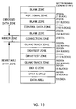
- the lead-in area of FIG. 12 is constituted as shown in FIG. 13.
- the lead-in area is formed of an embossed data zone, a mirror zone, and a rewritable data zone.
- the embossed data zone includes a plurality of blank zones, a reference signal zone, and a control data zone.
- the mirror zone includes a connection zone.
- the rewritable data zone includes guard track zones, a disk test zone, a drive test zone, a disk ID zone, defect management areas DMA1 and DMA2, and a data area.
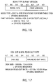
- the blank zone shall contain embossed data fields. These data fields shall contain embossed data (00h).
- the reference signal zone shall contain embossed data fields. These data fields shall contain embossed data of a reference code.
- the reference code is comprised of one ECC block (16 sectors) starting from the sector number 192512 (2F000h) in the lead-in area.
- Each sector's main data of 2048 bytes (2k bytes) is defined according to the following manner. First, the sector's main data of 2048 bytes (D0 to D2047) which repeat the data symbol "172" is produced. Then, the reference code for 16 sectors is produced by adding scramble data to the sector's main data. More specifically, the scramble data of the initial preset number '0' is added to the sector's main data. However, as to the part D0 to D159 of sector 0, the scramble data is masked and the addition of scramble data is not carried out.
- the control data zone shall contain embossed data fields. These data fields shall contain embossed data of control data.
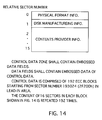
- the control data is comprised of the 192 ECC blocks starting from the sector number 193024 (2F200h) in the lead-in area. The content of 16 sectors in each block, as shown in FIG. 14, is repeated 192 times.
- each said block contains physical format information at relative sector number 0, disk manufacturing information at relative sector number 1, and contents provider information at relative sector numbers 2 to 15.
- FIG. 15 shows the configuration of the physical format information of FIG. 14.
- disk size and minimum read out rate information (1 byte) is written as shown in FIG. 17.
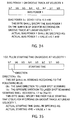
- disk structure information (1 byte) is written as shown in FIG. 18.
- First to fourth bits (b0 to b3) of this information are used to describe the layer type of the recording layer; fifth bit (b4) is used to describe the track path; sixth to seventh bits (b5 and b6) are used to indicate the number of the recording layers; and the eighth bit (b7) is provided for reservation.
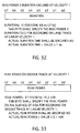
- recorded density information (1 byte) is written as shown in FIG. 19.
- First to fourth bits (b0 to b3) of this information are used to describe the track density; and fifth to eighth bits (b4 to b7) thereof are used to describe the linear density.
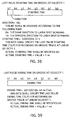
- data area allocation information (12 bytes) is written as shown in FIG. 20.
- Fifth to seventh bytes of this information are used to describe the start sector number of the data area, and ninth to eleventh bytes thereof are used to describe the end sector number of the data area.
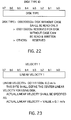
- disk type ID information (1 byte) is written as shown in FIG. 22.
- this information is 00000000b, it is indicated that the disk is a read-only disk without case or housing.
- bias power 1 on the land track at velocity 1 (1 byte) is written as shown in FIG. 26.
- This data byte shall specify bias power 1 on the surface of the disk for recording on the land track at linear velocity 1. For instance, when this data is 00101101b, this bias power 1 is 4.5 mW.
- first pulse starting time on the land track at velocity 1 (1 byte) is written as shown in FIG. 27.
- This data comprises a direction bit (eighth bit b7) and starting time bits (first to seventh bits b0 to b6) which indicate the first pulse starting time on the land track at linear velocity 1.
- eighth bit b7 is 0b
- the first pulse has the same direction to the laser spot scanning.
- eighth bit b7 is 1b
- the first pulse has the opposite direction to the laser spot scanning.
- first pulse ending time on the land track at velocity 1 (1 byte) is written as shown in FIG. 28.
- This data byte shall specify first pulse ending time (TEFP) for recording on the land track at linear velocity 1. For instance, when data is 00110011b, this ending time is 51 ns (3TW/2).
- TMP multi-pulse duration
- first to seventh bits b0 to b6 which indicate the last pulse starting time on the land track at linear velocity 1.
- eighth bit b7 is 0b
- the last pulse has the same direction to the laser spot scanning.
- eighth bit b7 is 1b
- the last pulse has the opposite direction to the laser spot scanning.
- bias power 2 duration on the land track at velocity 1 (1 byte) is written as shown in FIG. 32.
- This data byte shall specify bias power 2 duration (TLE) for recording on the land track at linear velocity 1.
- this duration time is 68 ns (2TW).
- bias power 1 on the groove track at velocity 1 (1 byte) is written as shown in FIG. 34.
- This data byte shall specify bias power 1 on the surface of the disk for recording on the groove track at linear velocity 1. For instance, when the data is 00101101b, this bias power 1 is 4.5 mW.
- first pulse starting time on the groove track at velocity 1 (1 byte) is written as shown in FIG. 35.
- This data comprises a direction bit (eighth bit b7) and starting time bits (first to seventh bits b0 to b6) which indicate the first pulse starting time on the groove track at linear velocity 1.
- eighth bit b7 0b
- the first pulse has the same direction to the laser spot scanning.
- eighth bit b7 is 1b
- the first pulse has the opposite direction to the laser spot scanning.
- first pulse ending time (TEFP) for recording on the groove track at linear velocity 1.
- TEFP first pulse ending time
- this ending time is 51 ns (3TW/2).
- TMP multi-pulse duration
- first to seventh bits b0 to b6 which indicate the last pulse starting time on the groove track at linear velocity 1.
- eighth bit b7 is 0b
- the last pulse has the same direction to the laser spot scanning.
- eighth bit b7 is 1b
- the last pulse has the opposite direction to the laser spot scanning.
- bias power 2 duration on the groove track at velocity 1 (1 byte) is written as shown in FIG. 40.
- This data byte shall specify bias power 2 duration (TLE) for recording on the groove track at linear velocity 1.
- this duration time is 68 ns (2TW).
- Bytes 66 to 479 of the physical format information of FIG. 15 are reserved for write conditions at velocities V2 to V24. All of these bytes shall be set to 00h.
- Bytes 480 to 2047 of the physical format information of FIG. 15 are reserved. All of these bytes shall be set to 00h.
- the data block containing the above-mentioned physical format information contents (FIGS. 15-41) is stored in the control data zone of FIG. 13, and the control data zone is arranged at the lead-in area of FIG. 12.
- the lead-in area is allocated at the inner side of information recording layer 10 of disk OD. Data read/write operations for respective disks can be suitably performed with reference to the physical format information contents recorded at the lead-in area of disk OD.
- control data zone having said physical format information contents can be provided on all of or part of areas MA1 to MA4 of FIG. 5 or FIG. 6.
Landscapes
- Engineering & Computer Science (AREA)
- Signal Processing (AREA)
- Software Systems (AREA)
- Theoretical Computer Science (AREA)
- Signal Processing For Digital Recording And Reproducing (AREA)
- Optical Recording Or Reproduction (AREA)
- Management Or Editing Of Information On Record Carriers (AREA)
Applications Claiming Priority (3)
| Application Number | Priority Date | Filing Date | Title |
|---|---|---|---|
| JP8068410A JPH09259576A (ja) | 1996-03-25 | 1996-03-25 | 複数管理領域を持つ情報記録ディスク |
| JP68410/96 | 1996-03-25 | ||
| JP6841096 | 1996-03-25 |
Publications (3)
| Publication Number | Publication Date |
|---|---|
| EP0798711A2 true EP0798711A2 (de) | 1997-10-01 |
| EP0798711A3 EP0798711A3 (de) | 1998-12-16 |
| EP0798711B1 EP0798711B1 (de) | 2002-09-25 |
Family
ID=13372888
Family Applications (1)
| Application Number | Title | Priority Date | Filing Date |
|---|---|---|---|
| EP97105050A Expired - Lifetime EP0798711B1 (de) | 1996-03-25 | 1997-03-25 | Platte zur Informationsaufzeichnung mit Verwaltungszonen |
Country Status (7)
| Country | Link |
|---|---|
| US (1) | US5878020A (de) |
| EP (1) | EP0798711B1 (de) |
| JP (1) | JPH09259576A (de) |
| KR (1) | KR970067327A (de) |
| CN (1) | CN1094630C (de) |
| DE (1) | DE69715710T2 (de) |
| TW (1) | TW403901B (de) |
Cited By (24)
| Publication number | Priority date | Publication date | Assignee | Title |
|---|---|---|---|---|
| WO1999065025A1 (en) * | 1998-06-12 | 1999-12-16 | Iomega Corporation | Method and apparatus for enabling/disabling drive features |
| WO2000054261A3 (en) * | 1999-03-08 | 2001-03-29 | Matsushita Electric Industrial Co Ltd | Recording drive information on recording medium |
| WO2001022416A1 (en) * | 1999-09-23 | 2001-03-29 | Koninklijke Philips Electronics N.V. | Method of immediate writing or reading files on a disc like recording medium |
| EP0997905A3 (de) * | 1998-10-10 | 2002-01-16 | SAMSUNG ELECTRONICS Co. Ltd. | Aufzeichnungsträger mit Reserveoberfläche für Defektmanagement und Reserveoberflächezuordnungsverfahren |
| EP1102249A4 (de) * | 1998-07-29 | 2002-07-31 | Matsushita Electric Industrial Co Ltd | Weidergabegerät und aufgezeichnetes medium |
| EP1098303A4 (de) * | 1999-05-21 | 2002-07-31 | Matsushita Electric Industrial Co Ltd | Optische platte, optisches plattenaufzeichnungsgerät/-wiedergabegerät und aufzeichnungsverfahren |
| US6590846B2 (en) | 1999-05-21 | 2003-07-08 | Matsushita Electric Industrial Co., Ltd. | Recordable optical disk |
| US6674707B2 (en) | 2000-01-17 | 2004-01-06 | Matsushita Electric Industrial Co., Ltd. | Digital recorded data reproducing device |
| US6697307B1 (en) | 1998-10-10 | 2004-02-24 | Samsung Electronics Co., Ltd. | Apparatus for assigning spare areas for defect management and apparatus for handling fragmented ECC blocks |
| WO2004029964A1 (en) * | 2002-09-25 | 2004-04-08 | Koninklijke Philips Electronics N.V. | Defect area management |
| WO2004055787A1 (en) * | 2002-12-13 | 2004-07-01 | Koninklijke Philips Electronics N.V. | Record carrier comprising multiple sets of recording parameters |
| EP1148494A3 (de) * | 2000-04-08 | 2005-02-16 | Samsung Electronics Co., Ltd. | Verfahren zur Überprüfung von Informationen in der Fehlermanagementzone einer optischen Platte |
| EP1600965A3 (de) * | 2004-05-25 | 2006-04-19 | Nec Corporation | Aufzeichnungssystem für optische Platte |
| EP1148493A3 (de) * | 2000-04-08 | 2006-09-13 | Samsung Electronics Co. Ltd. | Verfahren zur Überprüfung von Informationen in der Fehlermanagementzone von optischen Platten und Gerät zur Durchführung des Verfahrens |
| US7167424B2 (en) | 1998-08-29 | 2007-01-23 | Samsung Electronics Co., Ltd. | Method for detecting servo error, apparatus therefor, disk which maintains quality of servo error signal, method of controlling servo of disk recording/reproducing apparatus, method of detecting tracking error, and method of detecting tilt error |
| EP1587104A3 (de) * | 2003-02-28 | 2007-01-24 | Pioneer Corporation | Einmal-beschreibbares Aufzeichnungsmedium |
| EP1509908A4 (de) * | 2002-05-31 | 2008-03-19 | Samsung Electronics Co Ltd | Mehrschichtiges optisches informationsspeichermedium und aufzeichnungs-/wiedergabeverfahren dafür |
| US7376861B2 (en) | 1998-12-30 | 2008-05-20 | Samsung Electronics Co., Ltd. | Recording medium for storing start position information for each zone and method and apparatus of managing data using the information |
| US7383411B2 (en) | 1998-12-30 | 2008-06-03 | Samsung Electronics Co., Ltd. | Recording medium for storing start position information for each zone and method of managing data using the information |
| EP1540648A4 (de) * | 2002-08-03 | 2008-12-24 | Samsung Electronics Co Ltd | Informationsspeichermedium und verfahren zum aufzeichnen und/oder wiedergeben in bezug auf das medium |
| US7471617B2 (en) | 2004-04-23 | 2008-12-30 | Nec Corporation | Optical disc medium having extended record control data areas, optical disc apparatus using the same, and data recording method on the same |
| DE19964405B4 (de) * | 1998-09-07 | 2016-10-27 | Lg Electronics Inc. | Verfahren und Vorrichtung zum Suchen des ersten verfügbaren, guten Ersatzblocks eines optischen Aufzeichnungsmediums |
| EP3109862A4 (de) * | 2014-08-06 | 2017-05-17 | Panasonic Intellectual Property Corporation of America | Aufzeichnungsmedium, wiedergabevorrichtung und wiedergabeverfahren |
| EP3979244A1 (de) * | 2014-08-06 | 2022-04-06 | Panasonic Intellectual Property Corporation of America | Aufzeichnungsmedium, wiedergabevorrichtung und wiedergabeverfahren |
Families Citing this family (112)
| Publication number | Priority date | Publication date | Assignee | Title |
|---|---|---|---|---|
| JP3861269B2 (ja) | 1996-07-16 | 2006-12-20 | ソニー株式会社 | 光ディスク装置、光ディスクの記録方法、光ディスク及び光ディスクの製造方法 |
| US6088323A (en) * | 1996-07-16 | 2000-07-11 | Sony Corporation | Optical disk, optical disk device, and optical disk recording method |
| CN1136554C (zh) * | 1996-10-25 | 2004-01-28 | 松下电器产业株式会社 | 具有摆动凸区和凹槽的光盘 |
| JP3178794B2 (ja) * | 1996-12-09 | 2001-06-25 | 富士通株式会社 | 情報記憶媒体の複写制御方法及び情報記憶媒体の複写装置 |
| US20050058039A1 (en) * | 1997-01-16 | 2005-03-17 | Yasuo Kamatani | Multi-standard optical disk and method and apparatus of reading from and recording to the disk |
| US6490235B1 (en) | 1997-08-07 | 2002-12-03 | Sony Corporation | Storage and reproduction apparatus with rotary control element for controlling operations |
| US6665690B2 (en) * | 1997-10-21 | 2003-12-16 | Sony Corporation | System and method for determining respective lengths of recording units used for recording different types of data on disc medium |
| KR100255191B1 (ko) * | 1997-12-31 | 2000-06-01 | 윤종용 | 광 디스크 재생장치에서 종류 검출을 위한 디스크와그 종류 검출방법 |
| US6128262A (en) * | 1998-02-13 | 2000-10-03 | International Business Machines Corporation | System for creating, reading and writing on rotatable information storage media, a method for customizing said media with timing information |
| EP2261920A3 (de) * | 1998-02-23 | 2011-03-09 | Kabushiki Kaisha Toshiba | Informationsaufzeichnungsmedium, Informationswiedergabeverfahren und -vorrichtung, und Informationsaufzeichnungsverfahren |
| KR100274400B1 (ko) * | 1998-05-09 | 2000-12-15 | 구자홍 | 차등구획된 여유영역을 갖는 광기록매체의 제조방법,기록/재생방법 및 그 장치 |
| US7406250B2 (en) * | 1998-05-15 | 2008-07-29 | Kabushiki Kaisha Toshiba | Information recording method and information reproducing method |
| KR100601598B1 (ko) * | 1998-06-15 | 2006-07-14 | 삼성전자주식회사 | 기록 방지 정보를 저장하는 기록 매체와 기록 방지 방법 |
| US6744713B1 (en) * | 1998-06-15 | 2004-06-01 | Samsung Electronics Co., Ltd. | Recording medium for storing write protection information and write protection method thereof |
| US7448021B1 (en) | 2000-07-24 | 2008-11-04 | Sonic Solutions, A California Corporation | Software engine for combining video or audio content with programmatic content |
| US20050182828A1 (en) * | 1999-04-21 | 2005-08-18 | Interactual Technologies, Inc. | Platform specific execution |
| US6941383B1 (en) | 2000-01-20 | 2005-09-06 | Interactual Technologies, Inc. | System, method and article of manufacture for java/javascript component in a multimedia synchronization framework |
| US6405203B1 (en) * | 1999-04-21 | 2002-06-11 | Research Investment Network, Inc. | Method and program product for preventing unauthorized users from using the content of an electronic storage medium |
| US6769130B1 (en) | 2000-01-20 | 2004-07-27 | Interactual Technologies, Inc. | System, method and article of manufacture for late synchronization during the execution of a multimedia event on a plurality of client computers |
| CN1367926A (zh) | 1999-04-21 | 2002-09-04 | 研究投资网络公司 | 存储在可移动存储媒体上的内容升级的制作的系统、方法及物品 |
| US7458091B1 (en) | 2000-01-20 | 2008-11-25 | Sonic Solutions, A California Corporation | System, method and article of manufacture for a business layer component in a multimedia synchronization framework |
| US6453420B1 (en) | 1999-04-21 | 2002-09-17 | Research Investment Network, Inc. | System, method and article of manufacture for authorizing the use of electronic content utilizing a laser-centric medium |
| US20060041639A1 (en) * | 1999-04-21 | 2006-02-23 | Interactual Technologies, Inc. | Platform detection |
| US7188193B1 (en) | 2000-01-20 | 2007-03-06 | Sonic Solutions, A California Corporation | System, method and article of manufacture for a synchronizer component in a multimedia synchronization framework |
| US7178106B2 (en) * | 1999-04-21 | 2007-02-13 | Sonic Solutions, A California Corporation | Presentation of media content from multiple media sources |
| US7346920B2 (en) * | 2000-07-07 | 2008-03-18 | Sonic Solutions, A California Corporation | System, method and article of manufacture for a common cross platform framework for development of DVD-Video content integrated with ROM content |
| US6529949B1 (en) * | 2000-02-07 | 2003-03-04 | Interactual Technologies, Inc. | System, method and article of manufacture for remote unlocking of local content located on a client device |
| US6519213B1 (en) | 1999-06-29 | 2003-02-11 | Oak Technology, Inc. | Method and apparatus for reading data from a disk |
| JP4300642B2 (ja) * | 1999-08-18 | 2009-07-22 | ソニー株式会社 | 記録媒体及び記録媒体の再生装置並びに再生方法 |
| JP4153629B2 (ja) * | 1999-09-29 | 2008-09-24 | 株式会社東芝 | 静止画像つき音声情報の編集方法 |
| US7065019B2 (en) | 1999-11-16 | 2006-06-20 | Lg Electronics Inc. | Method for recording data on optical recording medium |
| KR100662271B1 (ko) * | 1999-11-16 | 2007-01-02 | 엘지전자 주식회사 | 광 기록매체의 데이터 기록 방법 |
| US7392481B2 (en) * | 2001-07-02 | 2008-06-24 | Sonic Solutions, A California Corporation | Method and apparatus for providing content-owner control in a networked device |
| US6957220B2 (en) | 2000-11-07 | 2005-10-18 | Research Investment Networks, Inc. | System, method and article of manufacture for tracking and supporting the distribution of content electronically |
| US20050251732A1 (en) * | 2000-01-20 | 2005-11-10 | Interactual Technologies, Inc. | System, method and article of manufacture for executing a multimedia event on a plurality of client computers using a synchronization host engine |
| US7046605B1 (en) * | 2000-06-28 | 2006-05-16 | Samsung Electronics Co., Ltd. | Recording medium for storing version information for maintaining recording and/or reproducing compatibility, and method and apparatus for managing the same |
| US7779097B2 (en) | 2000-09-07 | 2010-08-17 | Sonic Solutions | Methods and systems for use in network management of content |
| US20080123491A1 (en) * | 2000-09-07 | 2008-05-29 | Samsung Electronics Co., Ltd | Optical recording medium having read-only storage area and writeable storage area and recording/reproducing apparatus and method therefor |
| US7689510B2 (en) | 2000-09-07 | 2010-03-30 | Sonic Solutions | Methods and system for use in network management of content |
| US7191442B2 (en) | 2000-10-30 | 2007-03-13 | Research Investment Network, Inc. | BCA writer serialization management |
| TW479224B (en) * | 2000-11-10 | 2002-03-11 | Via Tech Inc | Method and circuit for controlling burst cutting area clock of compact disk |
| US6839802B2 (en) | 2000-12-08 | 2005-01-04 | International Business Machines Corporation | Method, system, and program for writing files to zone formatted storage media to improve data transfer rates |
| US6985426B2 (en) * | 2001-02-23 | 2006-01-10 | Matsushita Electric Industrial Co., Ltd. | Method and apparatus for recording optical information including dummy data, and optical disk having such data recorded thereon |
| JP3674531B2 (ja) * | 2001-04-12 | 2005-07-20 | 株式会社日立製作所 | ファイル管理方法、ファイル管理装置、プログラム |
| US20030123302A1 (en) * | 2001-06-05 | 2003-07-03 | Thompson Robert F. | Limited play optical devices with interstitial reactive layer and methods of making same |
| JP2003203341A (ja) * | 2001-11-02 | 2003-07-18 | Victor Co Of Japan Ltd | 光ディスク、光ディスク記録再生装置及び光ディスク記録再生方法 |
| KR20100101191A (ko) * | 2002-01-22 | 2010-09-16 | 파나소닉 주식회사 | 다층 정보 기록 매체, 정보 기록 방법, 정보 재생 방법 및 프로그램 |
| TWI258135B (en) * | 2002-01-25 | 2006-07-11 | Sony Corp | Information recording device and method, information reproducing device and method, recording medium, and disc recording medium |
| JP4078198B2 (ja) * | 2002-01-31 | 2008-04-23 | 松下電器産業株式会社 | 情報記録媒体および欠陥管理領域の位置決定方法 |
| AU2003201839A1 (en) * | 2002-04-01 | 2003-10-23 | Sony Corporation | Recording method for recording data on a storage medium |
| KR20040027259A (ko) * | 2002-09-26 | 2004-04-01 | 엘지전자 주식회사 | 1 회 기록 가능한 광디스크의 디펙트 영역 관리방법 |
| AU2003264977B2 (en) * | 2002-09-26 | 2009-03-26 | Lg Electronics Inc. | Optical disc, method and apparatus for managing a defective area on an optical disc of write once type |
| KR20040028469A (ko) * | 2002-09-30 | 2004-04-03 | 엘지전자 주식회사 | 1 회 기록 가능한 광디스크의 디펙트 영역 관리방법 |
| US7233550B2 (en) | 2002-09-30 | 2007-06-19 | Lg Electronics Inc. | Write-once optical disc, and method and apparatus for recording management information on write-once optical disc |
| ATE462184T1 (de) | 2002-12-11 | 2010-04-15 | Lg Electronics Inc | Überschreibverfahren und informationsaufzeichnungsverfahren für eine einmalig beschreibbare optische diskette |
| JP2006510160A (ja) * | 2002-12-11 | 2006-03-23 | エルジー エレクトロニクス インコーポレーテッド | 追記型光ディスクへの上書きの管理方法及び装置 |
| US7372788B2 (en) * | 2003-01-14 | 2008-05-13 | Lg Electronics Inc. | Method for managing defective area on write-once optical recording medium, and optical recording medium using the same |
| US7672204B2 (en) * | 2003-01-27 | 2010-03-02 | Lg Electronics Inc. | Optical disc, method and apparatus for managing a defective area on an optical disc |
| TWI314315B (en) * | 2003-01-27 | 2009-09-01 | Lg Electronics Inc | Optical disc of write once type, method, and apparatus for managing defect information on the optical disc |
| KR100750109B1 (ko) * | 2003-02-15 | 2007-08-21 | 삼성전자주식회사 | 정보 저장매체 |
| US20040160799A1 (en) * | 2003-02-17 | 2004-08-19 | Park Yong Cheol | Write-once optical disc, and method and apparatus for allocating spare area on write-once optical disc |
| US7643390B2 (en) * | 2003-02-21 | 2010-01-05 | Lg Electronics Inc. | Write-once optical recording medium and defect management information management method thereof |
| US7499383B2 (en) * | 2003-02-21 | 2009-03-03 | Lg Electronics Inc. | Write-once optical disc and method for managing spare area thereof |
| US7675828B2 (en) * | 2003-02-25 | 2010-03-09 | Lg Electronics Inc. | Recording medium having data structure for managing at least a data area of the recording medium and recording and reproducing methods and apparatuses |
| TWI291168B (en) * | 2003-02-25 | 2007-12-11 | Lg Electronics Inc | Defect management method for optical recording medium and optical recording medium using the same |
| US7188271B2 (en) * | 2003-02-25 | 2007-03-06 | Lg Electronics Inc. | Write-once optical disc, and method and apparatus for recording management information on write-once optical disc |
| BRPI0318160B1 (pt) * | 2003-03-04 | 2016-05-31 | Lg Electronics Inc | método para gravação em meio de gravação óptica, aparelho para gravação em e reprodução de um meio de gravação óptica e meio de gravação óptica |
| TWI328805B (en) * | 2003-03-13 | 2010-08-11 | Lg Electronics Inc | Write-once recording medium and defective area management method and apparatus for write-once recording medium |
| EP1623422A1 (de) * | 2003-05-09 | 2006-02-08 | LG Electronics Inc. | Aufzeichnungsmedium mit einer datenstruktur zur verwaltung mindestens eines datenbereichs des aufzeichnungsmediums und aufzeichnungs- und wiedergabeverfahren und vorrichtungen |
| MY141431A (en) * | 2003-05-09 | 2010-04-30 | Lg Electronics Inc | Recording medium having data structure for managing at least a data area of the recording medium and recording and reproducing methods and apparatuses |
| TWI405191B (zh) * | 2003-05-09 | 2013-08-11 | Lg Electronics Inc | 單寫型光碟及由單寫型光碟回復碟片管理資訊的方法與裝置 |
| MXPA05012044A (es) * | 2003-05-09 | 2006-02-03 | Lg Electronics Inc | Disco optico de una sola escritura, metodo y aparato par recuperacion de informacion de administracion de disco del disco optico de una sola escritura. |
| JP4533892B2 (ja) * | 2003-07-04 | 2010-09-01 | エルジー エレクトロニクス インコーポレイティド | 追記型光ディスクの上書きを管理する方法及び装置 |
| DE602004020992D1 (de) * | 2003-07-14 | 2009-06-18 | Lg Electronics Inc | Einmalbeschreibbarer optischer datenträger, verfahren und vorrichtung zum aufzeichnen von verwaltungsinformationen auf einem einmalbeschreibbaren optischen datenträger |
| KR20050009031A (ko) * | 2003-07-15 | 2005-01-24 | 엘지전자 주식회사 | 1회 기록 가능한 광디스크 및 광디스크의 관리정보 기록방법 |
| ES2341859T3 (es) * | 2003-08-05 | 2010-06-29 | Lg Electronics, Inc. | Disco optico de escritura unica y metodo y aparato para grabar/reproducir informacion de gestion en/desde el disco optico. |
| US7313065B2 (en) | 2003-08-05 | 2007-12-25 | Lg Electronics Inc. | Write-once optical disc, and method and apparatus for recording/reproducing management information on/from optical disc |
| US7577073B2 (en) * | 2003-08-08 | 2009-08-18 | Koninklijke Philips Electronics N.V. | Defect area management |
| KR101024904B1 (ko) * | 2003-08-14 | 2011-03-31 | 엘지전자 주식회사 | 기록매체, 기록방법, 기록장치 및 기록재생시스템 |
| EP1665261B1 (de) * | 2003-09-08 | 2013-11-27 | LG Electronics Inc. | Einmal beschreibbarer optischer datenträger und verfahren und vorrichtung zum aufzeichnen von managementinformationen auf dem einmal beschreibbaren optischen datenträger |
| BRPI0414213A (pt) * | 2003-09-08 | 2006-10-31 | Lg Electronics Inc | método e aparelho de gerenciar meio fìsico de gravação e meio fìsico de gravação |
| KR101049137B1 (ko) * | 2003-09-08 | 2011-07-15 | 엘지전자 주식회사 | 1회 기록가능한 광디스크, 및 1회 기록가능한광디스크상에서 관리 정보를 기록하는 방법 및 장치 |
| KR20050027787A (ko) * | 2003-09-16 | 2005-03-21 | 삼성전자주식회사 | 데이터 기록 상태 정보를 제공하는 광 디스크 |
| KR100964685B1 (ko) * | 2003-10-20 | 2010-06-21 | 엘지전자 주식회사 | 1회 기록가능한 광디스크 및 광디스크의 기록재생방법과기록재생장치 |
| KR100975340B1 (ko) * | 2003-10-28 | 2010-08-12 | 삼성전자주식회사 | 광 기록/재생장치 및 그의 데이터 기록방법 |
| KR100555945B1 (ko) * | 2004-01-08 | 2006-03-03 | 삼성전자주식회사 | 재기록 가능한 광 매체에 데이터를 추가 기록하기 위한기록제어방법 및 빈 영역 관리방법 |
| KR101113866B1 (ko) * | 2004-03-19 | 2012-03-02 | 엘지전자 주식회사 | 기록매체내에 기록되는 데이터 구조 및 데이터 기록방법과기록장치 |
| KR101024916B1 (ko) * | 2004-03-19 | 2011-03-31 | 엘지전자 주식회사 | 1회 기록 가능한 고밀도 광디스크의 데이터 기록 방법 및장치 |
| US7383382B2 (en) * | 2004-04-14 | 2008-06-03 | Microsoft Corporation | System and method for storage power, thermal and acoustic management in server systems |
| US7706230B2 (en) * | 2004-05-13 | 2010-04-27 | Lg Electronics, Inc. | Recording medium, read/write method thereof and read/write apparatus thereof |
| KR101049117B1 (ko) * | 2004-06-08 | 2011-07-14 | 엘지전자 주식회사 | 1회 기록 가능한 광디스크 및 광디스크의 관리정보 기록방법, 디스크 클로징 방법 및 기록재생 장치 |
| KR101014727B1 (ko) * | 2004-06-23 | 2011-02-16 | 엘지전자 주식회사 | 1회 기록 가능한 광디스크의 중첩 기록 방법 및 장치 |
| JP2006012321A (ja) * | 2004-06-28 | 2006-01-12 | Hitachi-Lg Data Storage Inc | ディスク装置、ディスク装置の情報記録再生方法及びディスクの回転速度制御方法 |
| KR101041809B1 (ko) * | 2004-07-27 | 2011-06-17 | 엘지전자 주식회사 | 광디스크 및 광디스크 제어정보 구성방법 및 이를 이용한광디스크 기록재생방법과 장치 |
| KR101041811B1 (ko) | 2004-08-02 | 2011-06-17 | 엘지전자 주식회사 | 광 저장매체의 기록 재생 방법 및 장치 |
| KR101012378B1 (ko) * | 2004-08-16 | 2011-02-09 | 엘지전자 주식회사 | 광 저장매체의 기록 재생 방법 및 장치 |
| KR101215370B1 (ko) * | 2004-09-14 | 2012-12-26 | 엘지전자 주식회사 | 기록매체 및 기록매체의 기록 재생 방법 및 장치 |
| US7613874B2 (en) * | 2004-10-14 | 2009-11-03 | Lg Electronics, Inc. | Recording medium, and a method and apparatus for overwriting data in the same |
| EP1807838A2 (de) * | 2004-10-25 | 2007-07-18 | Koninklijke Philips Electronics N.V. | Fehlerbehebungsstrategie für blu-ray-platten |
| JP2006155802A (ja) * | 2004-11-30 | 2006-06-15 | Toshiba Corp | 情報記憶媒体、スタンパー、管理情報記録装置、ディスク装置、管理情報再生方法 |
| US7461202B2 (en) * | 2005-05-03 | 2008-12-02 | International Business Machines Corporation | Method and apparatus using hard disk drive for enhanced non-volatile caching |
| ATE502427T1 (de) * | 2005-07-06 | 2011-04-15 | Graaf B V V D | Trommelmotorantrieb und dessen verwendung |
| US7555715B2 (en) * | 2005-10-25 | 2009-06-30 | Sonic Solutions | Methods and systems for use in maintaining media data quality upon conversion to a different data format |
| KR101227485B1 (ko) * | 2005-11-25 | 2013-01-29 | 엘지전자 주식회사 | 기록매체 및 기록매체의 결함관리 정보 기록방법과기록장치 |
| KR20070058292A (ko) * | 2005-12-02 | 2007-06-08 | 엘지전자 주식회사 | 기록매체, 기록매체 기록재생 방법 및 장치와 기록매체클로징 방법 |
| US7808867B2 (en) * | 2006-02-01 | 2010-10-05 | Wellen Sham | System with read protecting function |
| US20080021963A1 (en) * | 2006-07-21 | 2008-01-24 | At&T Corp. | Content dissemination using a multi-protocol converter |
| JP2008047212A (ja) * | 2006-08-15 | 2008-02-28 | Nec Corp | 情報記録媒体、情報記録媒体の記録方法、及び情報記録再生装置 |
| US8015350B2 (en) * | 2006-10-10 | 2011-09-06 | Seagate Technology Llc | Block level quality of service data in a data storage device |
| TWI424435B (zh) * | 2009-08-31 | 2014-01-21 | Phison Electronics Corp | 對快閃記憶體下達程式化指令的方法、控制器與儲存系統 |
| US8898761B2 (en) * | 2011-01-13 | 2014-11-25 | International Business Machines Corporation | Systems and methods for generating and validating configuration files for computing devices |
| JP2024046317A (ja) * | 2022-09-22 | 2024-04-03 | 株式会社東芝 | 磁気ディスク装置 |
Family Cites Families (9)
| Publication number | Priority date | Publication date | Assignee | Title |
|---|---|---|---|---|
| JPH0223417A (ja) * | 1988-07-13 | 1990-01-25 | Matsushita Electric Ind Co Ltd | 情報記録方式と情報記録媒体 |
| US5150339A (en) * | 1989-04-24 | 1992-09-22 | Hitachi, Ltd. | Optical disk medium and its application method and system |
| US5257370A (en) * | 1989-08-29 | 1993-10-26 | Microsoft Corporation | Method and system for optimizing data caching in a disk-based computer system |
| JP2827495B2 (ja) * | 1990-10-22 | 1998-11-25 | 松下電器産業株式会社 | 情報媒体の記録方法、情報再生方法および情報再生装置 |
| US5241531A (en) * | 1990-11-07 | 1993-08-31 | Matsushita Graphic Communication Systems, Inc. | Storage medium having read/write storage region and read-only storage region and a method for managing defective sectors in the storage medium |
| JP3463352B2 (ja) * | 1993-07-23 | 2003-11-05 | ソニー株式会社 | 再生装置 |
| US5596564A (en) * | 1993-10-08 | 1997-01-21 | Matsushita Electric Industrial Co., Ltd. | Information recording medium and apparatus and method for recording and reproducing information |
| EP0651391A3 (de) * | 1993-10-29 | 1997-02-05 | Tokyo Shibaura Electric Co | Gewindebefestigung. |
| EP0727774B1 (de) * | 1994-08-31 | 2000-07-26 | Sony Corporation | Optische platte und aufzeichnungs- und/oder wiedergabegerät |
-
1996
- 1996-03-25 JP JP8068410A patent/JPH09259576A/ja active Pending
-
1997
- 1997-03-14 TW TW086103194A patent/TW403901B/zh not_active IP Right Cessation
- 1997-03-21 KR KR1019970009665A patent/KR970067327A/ko not_active Ceased
- 1997-03-24 US US08/826,401 patent/US5878020A/en not_active Expired - Lifetime
- 1997-03-25 EP EP97105050A patent/EP0798711B1/de not_active Expired - Lifetime
- 1997-03-25 CN CN97104546A patent/CN1094630C/zh not_active Expired - Lifetime
- 1997-03-25 DE DE69715710T patent/DE69715710T2/de not_active Expired - Lifetime
Cited By (68)
| Publication number | Priority date | Publication date | Assignee | Title |
|---|---|---|---|---|
| WO1999065025A1 (en) * | 1998-06-12 | 1999-12-16 | Iomega Corporation | Method and apparatus for enabling/disabling drive features |
| EP1102249A4 (de) * | 1998-07-29 | 2002-07-31 | Matsushita Electric Industrial Co Ltd | Weidergabegerät und aufgezeichnetes medium |
| US7590034B2 (en) | 1998-08-29 | 2009-09-15 | Samsung Electronics Co., Ltd. | Method for detecting servo error, apparatus therefor, disk which maintains quality of servo error signal, method of controlling servo of disk recording/reproducing apparatus, method of detecting tracking error, and method of detecting tilt error |
| US7167424B2 (en) | 1998-08-29 | 2007-01-23 | Samsung Electronics Co., Ltd. | Method for detecting servo error, apparatus therefor, disk which maintains quality of servo error signal, method of controlling servo of disk recording/reproducing apparatus, method of detecting tracking error, and method of detecting tilt error |
| DE19964405B4 (de) * | 1998-09-07 | 2016-10-27 | Lg Electronics Inc. | Verfahren und Vorrichtung zum Suchen des ersten verfügbaren, guten Ersatzblocks eines optischen Aufzeichnungsmediums |
| US7177250B2 (en) | 1998-10-10 | 2007-02-13 | Samsung Electronics Co., Ltd. | Apparatus for assigning spare areas for defect management and apparatus for handling fragmented ECC blocks |
| US7933178B2 (en) | 1998-10-10 | 2011-04-26 | Samsung Electronics Co., Ltd. | Apparatus for recording/reproducing data from a data are including a spare area for defect management allocated in reverse order from rearmost units of data area |
| US6879553B2 (en) | 1998-10-10 | 2005-04-12 | Samsung Electronics Co., Ltd. | Apparatus for assigning spare areas for defect management and apparatus for handling fragmented ECC blocks |
| US7522490B2 (en) | 1998-10-10 | 2009-04-21 | Samsung Electronics Co., Ltd. | Apparatus for assigning spare areas for defect management and apparatus for handling fragmented ECC blocks |
| SG95606A1 (en) * | 1998-10-10 | 2003-04-23 | Samsung Electronics Co Ltd | Recording medium having spare area for defect management and method of allocating spare area |
| US6556522B1 (en) | 1998-10-10 | 2003-04-29 | Samsung Electronics Co., Ltd. | Recording medium having spare areas for defect management and method of allocating spare areas |
| US6560177B2 (en) | 1998-10-10 | 2003-05-06 | Samsung Electronics Co., Ltd. | Recording medium having spare areas for defect management and method of allocating spare areas |
| US6747929B1 (en) | 1998-10-10 | 2004-06-08 | Samsung Electronics Co., Ltd. | Recording medium having spare areas for defect management and method of allocating spare areas |
| US6587413B2 (en) | 1998-10-10 | 2003-07-01 | Samsung Electronics Co., Ltd. | Recording medium having spare areas for defect management and method of allocating spare areas |
| US7085206B2 (en) | 1998-10-10 | 2006-08-01 | Samsung Electronics Co., Ltd. | Apparatus for assigning spare areas for defect management and apparatus for handling fragmented ECC blocks |
| US6594208B1 (en) | 1998-10-10 | 2003-07-15 | Samsung Electronics Co., Ltd. | Method for handling fragmented blocks and allocating spare areas for defect management of a recording medium |
| EP0997905A3 (de) * | 1998-10-10 | 2002-01-16 | SAMSUNG ELECTRONICS Co. Ltd. | Aufzeichnungsträger mit Reserveoberfläche für Defektmanagement und Reserveoberflächezuordnungsverfahren |
| US6697307B1 (en) | 1998-10-10 | 2004-02-24 | Samsung Electronics Co., Ltd. | Apparatus for assigning spare areas for defect management and apparatus for handling fragmented ECC blocks |
| US7085207B2 (en) | 1998-10-10 | 2006-08-01 | Samsung Electronics Co., Ltd. | Apparatus for assigning spare areas for defect management and apparatus for handling fragmented ECC blocks |
| SG127682A1 (en) * | 1998-10-10 | 2006-12-29 | Samsung Electronics Co Ltd | Method of handling fragmented blocks of a disk |
| US7116614B2 (en) | 1998-10-10 | 2006-10-03 | Samsung Electronics Co., Ltd. | Apparatus for assigning spare areas for defect management and apparatus for handling fragmented ECC blocks |
| US7626902B2 (en) | 1998-10-10 | 2009-12-01 | Samsung Electronics Co., Ltd. | Method for reproducing data from a data area including a spare area for defect management allocated in reverse order from rearmost units of data area |
| US7421622B2 (en) | 1998-12-30 | 2008-09-02 | Samsung Electronics Co., Ltd. | Recording medium for storing start position information for each zone and method of managing data using the information |
| US7945809B2 (en) | 1998-12-30 | 2011-05-17 | Samsung Electronics Co., Ltd. | Recording medium for storing start position information for each zone and method and apparatus of managing data using the information |
| US7603537B2 (en) | 1998-12-30 | 2009-10-13 | Samsung Electronics Co., Ltd. | Recording medium for storing start position information for each zone and method of managing data using the information |
| US7401250B2 (en) | 1998-12-30 | 2008-07-15 | Samsung Electronics Co., Ltd. | Recording medium for storing start position information for each zone and method and apparatus of managing data using the information |
| US7383411B2 (en) | 1998-12-30 | 2008-06-03 | Samsung Electronics Co., Ltd. | Recording medium for storing start position information for each zone and method of managing data using the information |
| US7904745B2 (en) | 1998-12-30 | 2011-03-08 | Samsung Electronics Co., Ltd. | Recording medium for storing start position information for each zone and method and apparatus of managing data using the information |
| US7721141B2 (en) | 1998-12-30 | 2010-05-18 | Samsung Electronics Co., Ltd. | Recording medium for storing start position information for each zone and method and apparatus of managing data using the information |
| US7698599B2 (en) | 1998-12-30 | 2010-04-13 | Samsung Electronics Co., Ltd. | Recording medium for storing start position information for each zone and method of managing data using the information |
| US7702961B2 (en) | 1998-12-30 | 2010-04-20 | Samsung Electronics Co., Ltd. | Recording medium for storing start position information for each zone and method of managing data using the information |
| US7376861B2 (en) | 1998-12-30 | 2008-05-20 | Samsung Electronics Co., Ltd. | Recording medium for storing start position information for each zone and method and apparatus of managing data using the information |
| WO2000054261A3 (en) * | 1999-03-08 | 2001-03-29 | Matsushita Electric Industrial Co Ltd | Recording drive information on recording medium |
| SG96668A1 (en) * | 1999-05-21 | 2003-06-16 | Matsushita Electric Industrial Co Ltd | Optical disk, and recording/reproducing apparatus and recording method for optical disk |
| US6791937B2 (en) | 1999-05-21 | 2004-09-14 | Matsushita Electric Industrial Co., Ltd. | Recordable optical disk |
| SG101523A1 (en) * | 1999-05-21 | 2004-01-30 | Matsushita Electric Industrial Co Ltd | Optical disk, and recording/reproducing apparatus and recording method for optical disk |
| SG101524A1 (en) * | 1999-05-21 | 2004-01-30 | Matsushita Electric Industrial Co Ltd | Optical disk, and recording/reproducing apparatus and recording method for optical disk |
| US6614749B2 (en) | 1999-05-21 | 2003-09-02 | Matsushita Electric Industrial Co., Ltd. | Recordable optical disk |
| US6606290B2 (en) | 1999-05-21 | 2003-08-12 | Matsushita Electric Industrial Co., Ltd. | Recordable optical disk |
| US6603731B2 (en) | 1999-05-21 | 2003-08-05 | Matsushita Electric Industrial Co., Ltd. | Recordable optical disk |
| US6603732B2 (en) | 1999-05-21 | 2003-08-05 | Matsushita Electric Industrial Co., Ltd. | Recordable optical disk |
| US6597654B2 (en) | 1999-05-21 | 2003-07-22 | Matsushita Electric Industrial Co., Ltd. | Recordable optical disk |
| US6597649B2 (en) | 1999-05-21 | 2003-07-22 | Matsushita Electric Industrial Co., Ltd. | Recordable optical disk |
| US6590846B2 (en) | 1999-05-21 | 2003-07-08 | Matsushita Electric Industrial Co., Ltd. | Recordable optical disk |
| EP1204099A3 (de) * | 1999-05-21 | 2002-11-27 | Matsushita Electric Industrial Co., Ltd. | Disque optique enregistrable |
| EP1204104A3 (de) * | 1999-05-21 | 2002-11-27 | Matsushita Electric Industrial Co., Ltd. | Wiedergabegerät für eine beschreibbare optische Platte |
| EP1204103A3 (de) * | 1999-05-21 | 2002-11-27 | Matsushita Electric Industrial Co., Ltd. | Aufzeichnungsgerät für eine beschreibbare optische Platte |
| EP1098303A4 (de) * | 1999-05-21 | 2002-07-31 | Matsushita Electric Industrial Co Ltd | Optische platte, optisches plattenaufzeichnungsgerät/-wiedergabegerät und aufzeichnungsverfahren |
| RU2269829C2 (ru) * | 1999-09-23 | 2006-02-10 | Конинклейке Филипс Электроникс Н.В. | Способ записи цифровых информационных сигналов на дисковом носителе записи, способ воспроизведения цифровых информационных сигналов на дисковом носителе записи, записывающее устройство и компьютерная система данных для записи цифровых информационных сигналов на носителе записи (варианты) |
| CZ301731B6 (cs) * | 1999-09-23 | 2010-06-09 | Koninklijke Philips Electronics N. V. | Zpusob okamžitého zápisu nebo ctení souboru ze záznamového média diskového typu |
| US6760288B2 (en) | 1999-09-23 | 2004-07-06 | Koninklijke Philips Electronics N.V. | Method of immediate writing or reading files on a disc like recording medium |
| WO2001022416A1 (en) * | 1999-09-23 | 2001-03-29 | Koninklijke Philips Electronics N.V. | Method of immediate writing or reading files on a disc like recording medium |
| US6674707B2 (en) | 2000-01-17 | 2004-01-06 | Matsushita Electric Industrial Co., Ltd. | Digital recorded data reproducing device |
| EP1148493A3 (de) * | 2000-04-08 | 2006-09-13 | Samsung Electronics Co. Ltd. | Verfahren zur Überprüfung von Informationen in der Fehlermanagementzone von optischen Platten und Gerät zur Durchführung des Verfahrens |
| EP1148494A3 (de) * | 2000-04-08 | 2005-02-16 | Samsung Electronics Co., Ltd. | Verfahren zur Überprüfung von Informationen in der Fehlermanagementzone einer optischen Platte |
| EP1509908A4 (de) * | 2002-05-31 | 2008-03-19 | Samsung Electronics Co Ltd | Mehrschichtiges optisches informationsspeichermedium und aufzeichnungs-/wiedergabeverfahren dafür |
| EP1540648A4 (de) * | 2002-08-03 | 2008-12-24 | Samsung Electronics Co Ltd | Informationsspeichermedium und verfahren zum aufzeichnen und/oder wiedergeben in bezug auf das medium |
| WO2004029964A1 (en) * | 2002-09-25 | 2004-04-08 | Koninklijke Philips Electronics N.V. | Defect area management |
| WO2004055787A1 (en) * | 2002-12-13 | 2004-07-01 | Koninklijke Philips Electronics N.V. | Record carrier comprising multiple sets of recording parameters |
| EP1587104A3 (de) * | 2003-02-28 | 2007-01-24 | Pioneer Corporation | Einmal-beschreibbares Aufzeichnungsmedium |
| US7260034B2 (en) | 2003-02-28 | 2007-08-21 | Pioneer Corporation | Write once recording medium, recording device and recording method for write one recording medium, and reproduction device and reproduction method for write once recording medium |
| US7420909B2 (en) | 2003-02-28 | 2008-09-02 | Pioneer Corporation | Write once recording medium, recording device and recording method for write one recording medium, and reproduction device and reproduction method for write once recording medium |
| EP1791126A3 (de) * | 2003-02-28 | 2010-11-17 | Pioneer Corporation | Einmalig beschreibbares Aufzeichnungsmedium, Aufzeichnungsvorrichtung und Verfahren dafür, Wiedergabevorrichtung und Verfahren dafür |
| US7471617B2 (en) | 2004-04-23 | 2008-12-30 | Nec Corporation | Optical disc medium having extended record control data areas, optical disc apparatus using the same, and data recording method on the same |
| US7551530B2 (en) | 2004-05-25 | 2009-06-23 | Nec Corporation | Optical disc recording system |
| EP1600965A3 (de) * | 2004-05-25 | 2006-04-19 | Nec Corporation | Aufzeichnungssystem für optische Platte |
| EP3109862A4 (de) * | 2014-08-06 | 2017-05-17 | Panasonic Intellectual Property Corporation of America | Aufzeichnungsmedium, wiedergabevorrichtung und wiedergabeverfahren |
| EP3979244A1 (de) * | 2014-08-06 | 2022-04-06 | Panasonic Intellectual Property Corporation of America | Aufzeichnungsmedium, wiedergabevorrichtung und wiedergabeverfahren |
Also Published As
| Publication number | Publication date |
|---|---|
| KR970067327A (ko) | 1997-10-13 |
| US5878020A (en) | 1999-03-02 |
| CN1164732A (zh) | 1997-11-12 |
| JPH09259576A (ja) | 1997-10-03 |
| EP0798711A3 (de) | 1998-12-16 |
| EP0798711B1 (de) | 2002-09-25 |
| DE69715710T2 (de) | 2003-05-15 |
| DE69715710D1 (de) | 2002-10-31 |
| TW403901B (en) | 2000-09-01 |
| CN1094630C (zh) | 2002-11-20 |
Similar Documents
| Publication | Publication Date | Title |
|---|---|---|
| EP0798711B1 (de) | Platte zur Informationsaufzeichnung mit Verwaltungszonen | |
| US5914928A (en) | Information recording disk having replacement area | |
| AU2004248483B2 (en) | Recording and/or reproducing method and apparatus | |
| US7248555B2 (en) | Device and method for recording information enabling reduced response time of a recording device | |
| CA2415497C (en) | Device and method for recording information | |
| US6606285B1 (en) | Method of immediate writing or reading files on a disc like recording medium | |
| US6671243B2 (en) | Information storage medium, information recording method, and information reproduction method | |
| US7203153B2 (en) | Recording medium, recording device, reproduction device, recording method and reproduction method | |
| US8854940B2 (en) | Device for and method of recording information | |
| EP1612790A1 (de) | Aufzeichnungsmedium, aufzeichnungseinrichtung, wiedergabeeinrichtung, aufzeichnungsverfahren und wiedergabeverfahren | |
| CA2414791C (en) | Mapping of consecutive regions for recording of information blocks | |
| US20070130419A1 (en) | Device for and method of recording digital information signals | |
| HK1091586A (en) | Recording medium, recording apparatus, reproduction apparatus, recording method and reproduction method | |
| CN101399070A (zh) | 具有可视图样的光学记录载体及其记录装置和方法 |
Legal Events
| Date | Code | Title | Description |
|---|---|---|---|
| PUAI | Public reference made under article 153(3) epc to a published international application that has entered the european phase |
Free format text: ORIGINAL CODE: 0009012 |
|
| 17P | Request for examination filed |
Effective date: 19970422 |
|
| AK | Designated contracting states |
Kind code of ref document: A2 Designated state(s): DE FR GB NL |
|
| PUAL | Search report despatched |
Free format text: ORIGINAL CODE: 0009013 |
|
| AK | Designated contracting states |
Kind code of ref document: A3 Designated state(s): DE FR GB NL |
|
| 17Q | First examination report despatched |
Effective date: 20001215 |
|
| GRAG | Despatch of communication of intention to grant |
Free format text: ORIGINAL CODE: EPIDOS AGRA |
|
| GRAG | Despatch of communication of intention to grant |
Free format text: ORIGINAL CODE: EPIDOS AGRA |
|
| GRAH | Despatch of communication of intention to grant a patent |
Free format text: ORIGINAL CODE: EPIDOS IGRA |
|
| GRAH | Despatch of communication of intention to grant a patent |
Free format text: ORIGINAL CODE: EPIDOS IGRA |
|
| GRAA | (expected) grant |
Free format text: ORIGINAL CODE: 0009210 |
|
| AK | Designated contracting states |
Kind code of ref document: B1 Designated state(s): DE FR GB NL |
|
| REG | Reference to a national code |
Ref country code: GB Ref legal event code: FG4D |
|
| REF | Corresponds to: |
Ref document number: 69715710 Country of ref document: DE Date of ref document: 20021031 |
|
| ET | Fr: translation filed | ||
| PLBE | No opposition filed within time limit |
Free format text: ORIGINAL CODE: 0009261 |
|
| STAA | Information on the status of an ep patent application or granted ep patent |
Free format text: STATUS: NO OPPOSITION FILED WITHIN TIME LIMIT |
|
| 26N | No opposition filed |
Effective date: 20030626 |
|
| REG | Reference to a national code |
Ref country code: FR Ref legal event code: PLFP Year of fee payment: 20 |
|
| PGFP | Annual fee paid to national office [announced via postgrant information from national office to epo] |
Ref country code: NL Payment date: 20160310 Year of fee payment: 20 Ref country code: DE Payment date: 20160322 Year of fee payment: 20 |
|
| PGFP | Annual fee paid to national office [announced via postgrant information from national office to epo] |
Ref country code: GB Payment date: 20160323 Year of fee payment: 20 Ref country code: FR Payment date: 20160208 Year of fee payment: 20 |
|
| REG | Reference to a national code |
Ref country code: DE Ref legal event code: R071 Ref document number: 69715710 Country of ref document: DE |
|
| REG | Reference to a national code |
Ref country code: NL Ref legal event code: MK Effective date: 20170324 |
|
| REG | Reference to a national code |
Ref country code: GB Ref legal event code: PE20 Expiry date: 20170324 |
|
| PG25 | Lapsed in a contracting state [announced via postgrant information from national office to epo] |
Ref country code: GB Free format text: LAPSE BECAUSE OF EXPIRATION OF PROTECTION Effective date: 20170324 |