EP0798795A2 - Electrodes des piles secondaires, leur procédé de production et dispositifs d'enduction de fluororésine pour leur production - Google Patents
Electrodes des piles secondaires, leur procédé de production et dispositifs d'enduction de fluororésine pour leur production Download PDFInfo
- Publication number
- EP0798795A2 EP0798795A2 EP97105037A EP97105037A EP0798795A2 EP 0798795 A2 EP0798795 A2 EP 0798795A2 EP 97105037 A EP97105037 A EP 97105037A EP 97105037 A EP97105037 A EP 97105037A EP 0798795 A2 EP0798795 A2 EP 0798795A2
- Authority
- EP
- European Patent Office
- Prior art keywords
- electrode
- fluororesin
- metal strip
- active material
- plate
- Prior art date
- Legal status (The legal status is an assumption and is not a legal conclusion. Google has not performed a legal analysis and makes no representation as to the accuracy of the status listed.)
- Withdrawn
Links
Images


Classifications
-
- H—ELECTRICITY
- H01—ELECTRIC ELEMENTS
- H01M—PROCESSES OR MEANS, e.g. BATTERIES, FOR THE DIRECT CONVERSION OF CHEMICAL ENERGY INTO ELECTRICAL ENERGY
- H01M4/00—Electrodes
- H01M4/02—Electrodes composed of, or comprising, active material
- H01M4/64—Carriers or collectors
-
- H—ELECTRICITY
- H01—ELECTRIC ELEMENTS
- H01M—PROCESSES OR MEANS, e.g. BATTERIES, FOR THE DIRECT CONVERSION OF CHEMICAL ENERGY INTO ELECTRICAL ENERGY
- H01M10/00—Secondary cells; Manufacture thereof
- H01M10/34—Gastight accumulators
- H01M10/345—Gastight metal hydride accumulators
-
- H—ELECTRICITY
- H01—ELECTRIC ELEMENTS
- H01M—PROCESSES OR MEANS, e.g. BATTERIES, FOR THE DIRECT CONVERSION OF CHEMICAL ENERGY INTO ELECTRICAL ENERGY
- H01M4/00—Electrodes
- H01M4/02—Electrodes composed of, or comprising, active material
- H01M4/24—Electrodes for alkaline accumulators
- H01M4/26—Processes of manufacture
-
- H—ELECTRICITY
- H01—ELECTRIC ELEMENTS
- H01M—PROCESSES OR MEANS, e.g. BATTERIES, FOR THE DIRECT CONVERSION OF CHEMICAL ENERGY INTO ELECTRICAL ENERGY
- H01M4/00—Electrodes
- H01M4/02—Electrodes composed of, or comprising, active material
- H01M4/24—Electrodes for alkaline accumulators
- H01M4/32—Nickel oxide or hydroxide electrodes
-
- H—ELECTRICITY
- H01—ELECTRIC ELEMENTS
- H01M—PROCESSES OR MEANS, e.g. BATTERIES, FOR THE DIRECT CONVERSION OF CHEMICAL ENERGY INTO ELECTRICAL ENERGY
- H01M4/00—Electrodes
- H01M4/02—Electrodes composed of, or comprising, active material
- H01M4/64—Carriers or collectors
- H01M4/70—Carriers or collectors characterised by shape or form
- H01M4/80—Porous plates, e.g. sintered carriers
- H01M4/808—Foamed, spongy materials
-
- Y—GENERAL TAGGING OF NEW TECHNOLOGICAL DEVELOPMENTS; GENERAL TAGGING OF CROSS-SECTIONAL TECHNOLOGIES SPANNING OVER SEVERAL SECTIONS OF THE IPC; TECHNICAL SUBJECTS COVERED BY FORMER USPC CROSS-REFERENCE ART COLLECTIONS [XRACs] AND DIGESTS
- Y02—TECHNOLOGIES OR APPLICATIONS FOR MITIGATION OR ADAPTATION AGAINST CLIMATE CHANGE
- Y02E—REDUCTION OF GREENHOUSE GAS [GHG] EMISSIONS, RELATED TO ENERGY GENERATION, TRANSMISSION OR DISTRIBUTION
- Y02E60/00—Enabling technologies; Technologies with a potential or indirect contribution to GHG emissions mitigation
- Y02E60/10—Energy storage using batteries
Definitions
- the present invention relates to a secondary battery electrode to be incorporated as electrodes into closed alkaline secondary batteries such as nickel-zinc secondary batteries, nickel-cadmium secondary batteries and nickel-hydrogen secondary batteries and to a process for producing the same, as well as, to a fluororesin coater employed for producing the same. More particularly, the present invention relates to an electrode which can constitute a secondary battery having excellent charge and discharge cycle life characteristics, in which dropping out of an active material powder carried on a collector is designed not to occur readily, particularly at the upper end portion of the electrode where a metal strip serving as a lead is fixed, so as to effectively avoid internal short-circuiting and to a process for producing it, as well as, to a fluororesin coater employed for producing it.
- nickel-hydrogen secondary batteries are ecologically harmless and has large discharge capacities, so that they are put into practical uses in increasing numbers as drive power sources for various electric and electronic appliances.
- the nickel-hydrogen secondary batteries include those having cylindrical overall shapes and those having rectangular overall shapes.
- the latter rectangular batteries generally have a structure as described below.
- a plurality of anode nickel electrodes and a plurality of cathode metal hydride (hydrogen absorbing alloy) electrodes are laminated alternately via separators having electrical insulating properties and liquid retaining properties such that the outermost layers may be the metal hydride electrodes to form a rectangular parallelepipedic electrode groups.
- the electrode group is introduced together with an alkaline electrolyte into a conductive can having a closed bottom, serving also as a cathode terminal, through the upper opening, and the upper opening of the can is then sealed.
- Such paste type nickel electrode A usually consists of a plate-like metal foam 1 having a three-dimensional reticular structure with predetermined dimensions in the X direction (width), Y direction (depth) and Z direction (height), as shown in Figure 1, such as a nickel foam, serving as a collector which is compressed partly on the surface at the upper end portion 1a to form recesses 2a,2b each having a rectangular plan view, and a predetermined amount of active material containing, for example, a nickel hydroxide powder as a major component carried in the gaps and on the surface of the metal foam 1.
- the positions where the recesses 2a,2b are formed are usually deviated a predetermined distance in the X direction from the center of the width (X) of the electrode A, and a metal strip 3 such as a nickel strip is fixed as a lead to one recess (recess 2a in Figure 1) by means of, for example, spot welding to form a metal strip fixed portion as indicated by the area 2A in Figure 1.
- a bag-like separator 4 having an opening only at the top, as shown in Figure 2 is provided, and a nickel electrode A shown in Figure 1 is housed in the separator 4 such that the upper end portion 1a, i.e. the metal strip fixed portion 2A, may direct upward to form a bag-like package.
- Such packages and metal hydride electrodes are arranged alternately as shown in Figure 3.
- the nickel electrode A is generally produced as follows.
- a powder of active material nickel hydroxide, an aqueous thickener solution containing a predetermined amount of thickener such as carboxymethyl cellulose dissolved therein and, as necessary, a powder of conductive material such as a carbonyl nickel powder and a cobalt monoxide powder are mixed in predetermined amounts to prepare an active material paste.
- this sheet A 1 has a surface area such that it can give an even number (two in Figure 4) of plate-like nickel electrodes A having the shape and dimensions as shown in Figure 1, and a compressed portion 2 1 , having a shape formed by combining two recesses 2a (2b) of the nickel electrode A shown in Figure 1 in the Z direction, is formed at a predetermined position. Since these recesses 2 1 are usually formed by compressing the sheet A 1 at a predetermined position with a punch having a predetermined shape, the compressed portion has a high density compared with other portions at this point.
- This sheet A 1 is subjected to a treatment of packing with the active material paste and then to drying treatment.
- the active material is secured in the internal gaps present in the sheet A 1 and also in the form of layer on the surface of the sheet A 1 .
- the sheet A 1 is subjected over the entire surface, for example, to rolling so as to adjust the overall thickness, as well as, to enhance adhesion between the gaps or the surface of the sheet A 1 and the active material secured therein or thereon, and thus the active material is carried on the sheet A 1 .
- each of the thus formed plates inevitably has a pair of recesses 2a, 2b at one end portion, as shown in Figure 1.
- the recesses 2a,2b of the thus obtained plate carry some active material powder in the gaps and on the surface, although the amount of the powder is not great compared with other portions, such active material powder is removed to expose the metal surface, and a metal strip 3 is spot welded thereto to form a metal strip fixed portion 2A and provide a nickel electrode A as shown in Figure 1.
- this nickel electrode A is a precursor of the electrode to be produced according to the present invention.
- the metal foam sheet A 1 serving as a collector has a very high porosity of 82 to 97 %, so that the packing density of the active material is high, and thus a secondary battery incorporated with such electrodes comes to have a great discharge capacity, advantageously.
- the active material (nickel hydroxide powder) carried on the metal foam is not excellent in the integrity of the particles and in the adhesion with the metal foam, giving rise to a problem as described below.
- the nickel hydroxide powder can drop out of the metal foam due to the influence of stress caused by such expansion and deformation to induce reduction in the capacity of the nickel electrode.
- the amount of dropped-out active material is increased, it can cause short-circuiting between the nickel electrodes (anodes) and the cathodes to reduce the cycle life characteristics of the battery.
- dropping out of the active material proceeds conspicuously during charging and discharging, and it also happens that the metal strip 3 separates from the metal strip fixed portion 2A.
- the phenomenon that the active material drops out and the phenomenon that the metal strip separates from the metal strip fixed portion are considered to be induced by the following factors.
- the electrode A in service.
- the electrode A In the initial stage of service, the electrode A is in service with the upper end portion 1a of the electrode A being exposed through the opening 4a of the bag-like separator 4, as shown in Figure 2, while the lower part of the side edge portion 1b and lower edge portion 1c being entirely enveloped by the separator 4. Accordingly, the lower part of the side edge portion 1b and the lower edge portion 1c of the electrode A as a whole assume a high resistance.
- the electric current applied and emitted to and from the electrode flows selectively through the upper end portion 1a of the electrode A. Accordingly, the current density at the upper end portion 1a of the electrode A is increased.
- nickel ⁇ -oxyhydroxide is likely to be formed in the active material carried at the upper end portion 1a of the electrode A, and the active material undergoes great expansion and deformation with the formation of nickel ⁇ -oxyhydroxide. Since the section at the upper end portion 1a is a cut surface appeared by cutting or punching as described above and has substantially no binder on it, dropping out of the active material develops seriously at this part. This phenomenon progresses conspicuously at the edge of the upper end portion 1a to which the electric current concentrates, causing internal short-circuiting.
- the alkaline electrolyte if permeated the portion 2A where the metal strip is fixed to the recess of the metal foam and the periphery around it, causes electrolytic corrosion between the recess of the metal foam and the metal strip which have different self potential values to loosen adhesion between them. In some worst cases, it can happen that the metal strip separates from the recess.
- the present inventors conceived that if at least the site where the metal strip is fixed is coated with a material having a capacity of binding the active material and also having high resistance, the upper end portion of the electrode comes to have an increased resistance to inhibit concentration of electric current thereto, and also the alkaline electrolyte can be prevented from permeating the metal strip fixed portion and around it, so that the active material can be prevented from dropping out of the electrode during charging and discharging, thus avoiding internal short-circuiting.
- the present invention provides a secondary electrode consisting of a plate-like metal foam; a recess formed by compressing depthwise the surface of the plate-like metal foam partly at the upper end portion; a metal strip fixed portion formed by fixing a metal strip to the recess; an active material carried on the entire plate-like metal foam; and a fluororesin film formed to cover at least the metal strip fixed portion.
- the present invention provides a secondary electrode in which the fluororesin film is particularly formed crosswise in the form of belt at least at the upper end portion including the metal strip fixed portion, or the fluororesin film is formed at least on the peripheral end faces and on the metal strip fixed portion of the plate-like metal foam.
- the present invention also provides a process for producing a secondary battery electrode including steps of packing a metal foam sheet having a compressed portion formed at a predetermined position on the surface thereof with an active material paste, followed by drying; applying a fluororesin over the entire surface of the metal foam sheet, followed by drying; removing the active material and the fluororesin present in the compressed portion, and rolling the resulting sheet, followed by cutting or punching of the sheet into a plate having a predetermined shape such that the plate may have a recess at one end portion; fixing a metal strip to the recess of the plate and thus defining a metal strip fixed portion to provide an electrode; and coating the electrode with a fluororesin crosswise in the form of belt along the end portion including the metal strip fixed portion (hereinafter referred to as the first process).
- the present invention further provides a process for producing a secondary battery electrode including steps of packing a metal foam sheet having a compressed portion formed at a predetermined position on the surface thereof with an active material paste, followed by drying; applying a fluororesin over the entire surface of the metal foam sheet, followed by drying; removing the active material and the fluororesin present in the compressed portion, and rolling the resulting sheet, followed by cutting or punching of the sheet into a plate having a predetermined shape such that the plate may have a recess at one end portion; fixing a metal strip to the recess of the plate and thus defining a metal strip fixed portion to provide an electrode; laminating a plurality of said electrode, and applying wear plates to the electrodes locating outermost respectively, the wear plates having a size sufficient to cover the surface of the electrode, followed by application of a pressure via the wear plates to the electrodes in the direction of lamination to form an electrode group in which the electrodes are brought into intimate contact with one another; and coating the electrode group with a fluororesin partly on the
- the present invention provides a coater for applying a fluororesin to an electrode consisting of a lower roll and an upper roll rotatable synchronously with the lower roll, which are arranged such that the roll surface of the former and that of the latter may oppose each other; an - electrode feeder which runs carrying an electrode thereon located between the lower roll and the upper roll; means for supplying a fluororesin suspension to the roll surface of the upper roll; and a groove defined at least on the roll surface of the upper roll.
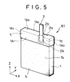
- FIG. 5 is a perspective view showing an exemplary electrode B1 produced according to the first process of the present invention.
- This electrode B1 is formed by coating the electrode A shown in Figure 1 with a fluororesin thin film 5 using an apparatus (to be described later) so that the upper end portion 1a of the metal foam 1 including the metal strip fixed portion 2A may be covered entirely. More specifically, the film 5 is formed so as to cover one face 1A 1 and the other face 1A 2 at the upper end portion including the metal strip fixed portion 2A crosswise in the form of belt (in the X direction), as well as, two lateral faces 1A 3 , 1A 4 at the upper end portion 1a and the upper face 1A 5 of the metal foam 1 which are the cut faces appeared when the plate was cut or punched out of the sheet.
- the upper end portion 1a is covered with the fluororesin film 5 having electrical insulating properties and water repellency, not only the upper end portion 1a comes to have an increased electrical resistance and improved water repellency but also integrity of the active material particles present at the upper end portion 1a is improved. Thus, it does not happen in the electrode in service that electric current flows selectively to the upper end portion 1a to increase the current density there. Accordingly, formation of nickel ⁇ -oxyhydroxide is minimized to inhibit expansion, deformation or dropping out of the active material which can be caused by accumulation of nickel ⁇ -oxyhydroxide, causing no internal short-circuiting.
- the metal strip 3 is buried at the recess 2a under the film 5, and permeation of the alkaline electrolyte into the metal strip fixed portion 2A is inhibited by the film 5 covering the entire upper end portion 1a, so that electrolytic corrosion hardly occurs between the metal strip 3 and the recess 2a, inhibiting separation of the metal strip 3 from the recess 2a.
- the film 5 is most preferably formed to cover the entire upper end portion 1a, it should be formed at least on the face 1A 1 including the metal strip fixed portion 2A crosswise in the form of belt.
- This electrode B1 is produced according to the first process described above.
- a metal foam sheet A 1 as shown in Figure 4 is first packed with an active material paste of a predetermined composition, followed by drying, according to the prior art methods described above.
- a fluororesin is applied over the entire surface of the thus treated sheet A 1 and dried so as to bind the active material with the fluororesin.
- the sheet may be immersed in a suspension of polytetrafluoroethylene, tetrafluoroethylene-hexafluoropropylene copolymer, perfluoroalkyl vinyl ether copolymer, ethylene chloride trifluoride resin, vinyl fluoride resin, etc.
- a suspension of tetrafluoroethylene having a concentration of 0.1 to 5 wt % is preferably employed.
- the active material and the fluororesin adhered to the compressed portion 2 1 are removed, for example, by means of brushing.
- the thus treated sheet A 1 is then subjected, for example, to rolling to adjust the thickness and increase the packing density of the active material, as well as, to allow the active material to be carried on the sheet A 1 with the aid of the fluororesin applied on it already.
- this sheet A 1 is cut or punched to form a plate having a pair of recesses 2a,2b at one edge portion, and a metal strip 3 is fixed to the recess 2a (or 2b), for example, by means of spot-welding to form a metal strip fixed portion 2A and provide an electrode A (precursor) as shown in Figure 1.
- the upper end portion 1a of the thus formed electrode A is coated with a fluororesin using the coater of the present invention as shown in front view in Figure 6 and in side view in Figure 7.
- a lower roll 6 and an upper roll 7 which operates in synchronization with the lower roll 6 are disposed such that the roll surface 6a of the former and the roll surface 7a of the latter may oppose each other.
- the roll surfaces 6a, 7a are designed to have a width such that it may substantially cover the dimension X of the metal strip fixed portion 2A at the upper end portion 1a of the electrode A shown in Figure 1 or a width a little shorter than it.
- An electrode feeder 8 such as a conveyor which runs carrying thereon the electrode A is disposed between the surface 6a of the lower roll 6 and the surface 7a of the upper roll 7.
- a press roller 9 is coaxially disposed behind the upper roll 7. The press roller 9 is adapted to be urged downward by a push spring mechanism 11 attached to an upper frame 10 so as to moderately press the electrode carried on the electrode feeder 8.
- the roll surface 6a of the lower roll 6 and the roll surface 7a of the upper roll 7 have grooves 6b and 7b having a desired width and a desired depth formed on the circumferences, respectively. More specifically, rings having grooves 6b,7b are formed using a rubbery material having an appropriate hardness, and these rings are fitted around rollers made, for example, of stainless steel.
- a tank 12 containing a fluororesin suspension is mounted on the upper frame 10.
- a suspension supply pipe 13 having a flow control valve 14 is connected to the tank 12, and a nozzle tip 13a attached to the distal end of the pipe 13 is located adjacent to the roll surface 7a of the upper roll 7.
- these elements constitute a mechanism for feeding the fluororesin suspension contained in the tank 12 to the roll surface 7a of the upper roll.
- the electrode A When the fluororesin is to be applied to the upper end portion 1a of the electrode A using this coater, the electrode A is loaded on the electrode feeder 8, as shown in Figure 8, and the lower roll 6 and the upper roll 7 are rotated.
- the electrode A is loaded such that the metal strip fixed portion 2A may direct upward and that the roll surface 7a of the upper roll 7 may oppose the metal strip fixed portion 2A.
- the electrode A is fed by the electrode feeder 8 in the direction of the arrow q shown in Figure 6 being pressed by the press roller 9 such that the metal strip fixed portion 2A may pass the gap between the roll surface 6a and the roll surface 7a being nipped lightly by them.
- the fluororesin suspension is supplied in a predetermined amount controlled by the flow control valve 14 from the nozzle tip 13a to the groove 7b of the upper roll 7.
- the fluororesin suspension 15 supplied to the groove 7b is applied to the upper end portion of the electrode A, and it also flows into the recessed portion 2 to bury the metal strip fixed portion 2A entirely, as shown in Figs 8 and 9.
- the extra portion of the suspension is discharged through the groove of the lower roll 6 to the bottom of the coater.
- the electrode A is processed into an electrode B1 as shown in Figure 5.
- the fluororesin suspension employable here includes suspensions of polytetrafluoroethylene, tetrafluoroethylene-hexafluoropropylene copolymer, perfluoroalkyl vinyl ether copolymer, ethylene chloride trifluoride resin, vinyl fluoride resin, etc. If the fluororesin concentration of such suspension is very low, the thickness of the resulting fluororesin film will be too small to exhibit the above-described effect sufficiently; whereas if it is very high, coating procedures become difficult to be unable to form a uniform film, and besides the reaction as the electrode can hardly occur. Based on such reasons, the fluororesin concentration of the suspension is preferably set to 5 to 50 wt %, more preferably 15 to 30 wt %.
- FIG 10 is a perspective view showing an exemplary electrode B2 prepared according to the second process of the present invention.
- an active material is carried on a plate-like metal foam 1 having a predetermined shape and predetermined dimensions, and a lead metal strip 3 is fixed to one of recesses 2a and 2b formed at the upper end portion.
- Peripheral end faces 1A, 1B 1 , 1B 2 , 1C of the metal foam 1 are entirely covered with a fluororesin thin film 5, and both electrode surfaces are also covered with the fluororesin thin film 5 each at the rim over a width of about 1 mm. Accordingly, each edge of the metal foam 1 and the edges of the recesses 2a, 2b are also covered with the fluororesin thin film 5.
- peripheral end faces 1A,1B 1 ,1B 2 ,1C and the rim of the electrode surfaces adjacent to the peripheral end faces are covered with the fluororesin thin film having electrical insulating properties and water repellency, even the active material particles exposed on the cut (punched) surfaces can be integrated by the fluororesin so that they may not drop out of the electrode.
- the fluororesin film 5 formed thereon acts to increase electrical resistance and to improve water repellency and also integrity of the active material particles.
- the metal strip fixed portion 2A since the metal strip 3 itself is coated with the fluororesin thin film, it is not brought into contact with the alkaline electrolyte. Further, since the recesses 2a,2b themselves and the edges thereof are also covered with the fluororesin film, the alkaline electrolyte does not permeate such portions. Thus, electrolytic corrosion is hardly induced between the metal strip 3 and the metal at the recess, preventing the metal strip 3 from separating from the metal strip fixed portion (recess).
- the thus constituted electrode B2 can be produced according to the second process of the present invention.
- the electrode A is produced in the same manner as in the first process.
- a plurality of electrode precursors A (seven in Figure 11) thus formed are laminated one after another such that the electrode surfaces thereof may oppose one another.
- the actual number of electrodes A to be laminated is preferably on the order of, for example, several hundred to several thousand, when industrial line operation is taken into consideration.
- a pair of wear plates 16a,16b are applied on the outermost electrodes A respectively, and a pressure P is applied via the wear plates 16a,16b to the electrodes A in the direction of lamination.
- the wear plates 16a,16b those having surface areas substantially the same as those of the electrodes A or slightly bigger than them are employed.
- the laminated electrodes A are brought into intimate contact with one another when they are pressed via the wear plates 16a,16b to form an electrode group C.
- the peripheral end faces 1A, 1B 1 , 1B 2 or 1C of the electrodes thus assembled form a plane, and ditches having a predetermined depth and opening at the top are formed by the recesses 2a,2b, with a metal strip 3 protruding from each ditch.
- a fluororesin is applied to the upper face, side faces, the bottom face and the ditches.
- a suspension of a desired fluororesin is first prepared, and the electrode group C may be subjected to spray coating using the suspension in the same manner as is carried out in an automotive body coating line or to brush coating.
- the entire electrode group C pressed between the wear plates 16a,16b may be as such immersed in the suspension.
- the metal strips 3 protruding from the electrode group C are applied with as little fluororesin as possible. If the metal strips 3 are applied with the fluororesin, their surface resistance increases, failing to serve as satisfactory leads. It is, therefore, necessary to remove the applied fluororesin at a later stage.
- the metal strips 3 protruding from the electrode group C are preferably covered with a removable cap such as of a resin and a rubber so that the metal strips 3 may not be coated with the fluororesin and may not loose the function as leads.
- the metal strips 3 may be covered by caps individually, or they may be covered together by one cap.
- the suspension employable here preferably is, for example, a dispersion adjusted such that the fluororesin concentration may be 50 wt % or less with water.
- a suspension having a fluororesin concentration of more than 50 wt % may be effective for preventing the active material from dropping out. However, it excessively covers the active material to lower its activity, causing deterioration in the battery characteristics.
- the surface of the electrode group C is coated with the suspension, and the suspension also flows into the ditches in which the metal strips are located, so that the metal strips 3 are also coated with the suspension. Since the electrodes are brought into intimate contact with one another, the suspension hardly flows through the contact interfaces of the electrodes to the central area on the hidden surfaces of each electrode. If penetrated, the depth of penetration is at most 1 mm or less, although it depends on the viscosity of the suspension employed.
- electrodes B2 according to the present invention in which the peripheral end faces 1A,1B 1 ,1B 2 ,1C, rims of the electrode surfaces around the peripheral end faces, the recesses 2a,2b and the edges of the recesses 2a,2b are coated with the fluororesin as shown in Figure 10 can be obtained.
- the drying treatment may be carried out after the electrode group C is disassembled as described above or before the electrode group C is disassembled.
- a spherical nickel hydroxide powder having a grain distribution of 1 to 200 ⁇ m and containing 4 parts by weight of Zn and 1.5 parts by weight of Co solid-dissolved therein are added 10 parts by weight of a carbonyl nickel powder having a grain distribution of 0.5 to 10 ⁇ m, 5 parts by weight of a cobalt monoxide powder having a grain distribution of 0.5 to 30 ⁇ m, 50 parts by weight of an aqueous carboxymethyl cellulose solution having a concentration of 2 wt % and 0.6 part by weight of a suspension of polytetrafluoroethylene (PTFE) having a concentration of 60 wt %, and the resulting mixture was kneaded to prepare an active material paste.
- PTFE polytetrafluoroethylene
- a nickel foam sheet with a porosity of 95 % having a rectangular compressed portion (length: 6 mm, width: 3 mm, depth: 0.15 mm) was provided, and the sheet was packed with the active material paste prepared above, followed by drying at a temperature of 120°C for 20 minutes.
- the thus treated sheet was immersed in a PTFE suspension having a concentration of 1.5 wt % and withdrawn therefrom, and after the sheet was dried at 100°C for 20 minutes, the active material and PTFE deposited to the recesses were brushed off.
- the resulting sheet was subjected to rolling under a pressure of 4 ton/cm 2 to shape the sheet to have a thickness of 0.6 mm.
- the rolled sheet was then punched to provide plates having a height of 48 mm, a width of 17 mm and a thickness of 0.6 mm.
- Each plate has on each side a recess (length; 3 mm, width 3 mm, depth 0.15 mm) formed by cutting the sheet crosswise along the center of the compressed portion. Then, a nickel strip is spot-welded to the recess of each plate to provide an electrode A shown in Figure 1.
- the coater shown in Figures 6 and 7 was employed to apply a PTFE suspension having a concentration of 2 to 60 wt % as indicated in the following Table 1 to the upper end portion 1a of each electrode A by dropping the PTFE suspension from the nozzle tip 13a of the coater to the roll surface 7a of the upper roll 7.
- both the lower roll 6 and the upper roll 7 have an overall diameter of 100 mm.
- the cores of these rolls 6,7 are made of SUS which are covered respectively on the circumferences with roll surfaces 6a and 7a made of a rubbery material having a rubber hardness of 60_, a width of 5 mm and a thickness of 5 mm.
- the roll surfaces 6a, 7a have grooves 6b,7b having a width of 2 mm and a depth of 1 mm formed on the circumferences respectively.
- electrodes B1 each of which is covered at the upper end portion 1a with a belt-like film 5 having a width about 1 mm longer than the length (3 mm) of the recess were obtained.
- a hydrogen absorbing alloy having the following composition: MmNi 3.2 CO 1.0 Al 0.2 Mn 0.4 (wherein Mm means a misch metal) was pulverized into a powder having an average particle size of 65 ⁇ m.
- Mm means a misch metal
- To 100 parts by weight of the powder thus obtained was added 5.26 parts by weight of a PTFE powder, and the resulting mixture was kneaded to make the PTFE powder fibrous, followed by addition of 15 parts by weight of water thereto to prepare a paste.
- the paste was clad to a punching nickel sheet (pore size: 1.5 mm, porosity 38 %, thickness 0.07 mm) on each surface and dried at a temperature of 80°C for 60 minutes, followed by rolling under a pressure of 3 ton/cm 2 to provide metal hydride electrodes having a thickness of 0.35 mm.
- separators to be incorporated into the battery were prepared as follows.
- FT-310 (trade name, a polyolefinic nonwoven fabric web manufactured by Japan Vilene Co., Ltd.) was washed with water to remove nonionic surfactant deposited on the surface and dried.
- the thus treated fabric web was immersed in a hot (100°C) conc. sulfuric acid having a concentration of 95 % for 30 minutes to effect sulfonation treatment on the surface.
- the thus treated fabric web was washed fully with flowing water and dried at a temperature of 80°C for one hour, it was immersed in an aqueous sodium hydroxide solution having a concentration of 1 % for 5 minutes, followed by washing with water.
- the thus obtained separators and the electrodes B1 were employed to provide bag-like packages as shown in Figure 2, which were then laminated alternately with the metal hydride electrodes to provide an electrode group.
- the electrode group was housed in a stainless steel can plated with nickel, and an electrolyte containing 0.6 N NaOH, 1N LiOH and 7N KOH was poured into the can. The can was then sealed to provide a rectangular nickel-hydrogen secondary battery having a thickness of 6 mm, a width of 17 mm, a height of 48 mm and a rated capacity of 600 mAh.
- Cycle life test was carried out against 1,000 sets of the thus assembled batteries, by repeating, at a temperature of 0°C, 500 times a cycle which was performed by charging at a current of 600 mA for 1.0 hour, discharging at a current of 600 mA for 1.25 hours such that the discharge end voltage may be 1V and a pause of 0.25 hour.
- the discharge capacity was measured, and the measured value was divided by the capacity at the initial stage of charging to calculate the mean value of the capacity retention rate (%).
- the concentration of the PTFE suspension to be applied to the electrode A is preferably set in the range of 5 to 50 wt %.
- the electrode B1 of the present invention dropping out of the active material powder carried thereon is inhibited to prevent effectively short-circuiting from occurring. This is the effect brought about by the fluororesin thin film having a high electrical resistance, water repellency and binding properties formed in the form of belt at the upper end portion of the electrode where the current density is increased during electrode reaction. Accordingly, the electrode B1 produced employing the coater of the present invention provides an extremely high industrial value as a secondary battery electrode having excellent charge and discharge cycle life characteristics.
- An active material paste was prepared by kneading 100 g of a spherical nickel hydroxide powder containing 4 wt% Zn and 1.5 wt% Co solid-dissolved therein and having a particle size of 5 to 50 ⁇ m, 10 g of a nickel powder having a particle size of 0.5 to 20 ⁇ m, 5 g of a cobalt monoxide powder having a particle size of 0.5 to 30 ⁇ m, 50 g of an aqueous carboxymethyl cellulose solution having a concentration of 2 wt % and 1 g of a PTFE suspension having a concentration of 60 wt %.
- a nickel foam sheet (porosity: 95 %) having a rectangular compressed portion (length: 6 mm, width: 3 mm, depth: 0.15 mm) formed by compressing the sheet depthwise at a predetermined position was provided, and the sheet was packed with the active material paste prepared above and then dried at a temperature of 120°C for 20 minutes.
- the thus treated sheet was immersed in a PTFE suspension having a concentration of 60 % and withdrawn therefrom, and after the sheet was dried at 100°C for 20 minutes, the active material and PTFE deposited on the compressed portion were brushed off.
- the resulting sheet was subjected to rolling under a pressure of 4 ton/cm 2 to shape the sheet to have a thickness of 0.7 mm.
- the rolled sheet was then punched to provide plates having a height of 38 mm, a width of 13 mm and a thickness of 0.7 mm.
- Each of the plates has on each side a recess (length; 3 mm, width 3 mm, depth 0.15 mm). Then, a nickel strip is spot-welded to one of the recesses of each plate to provide an electrode.
- the electrode group C was uniformly spray-coated on the surface with a PTFE suspension having a concentration as indicated in Table 2 and dried at a temperature of 80°C for 5 minutes. The pressure applied by the wear plates was then released, and the electrode group C was disassembled to give nickel electrodes B2 of the present invention.
- a hydrogen absorbing alloy having the following composition: MmNi 3.2 CO 1.0 Al 0.2 Mn 0.4 (wherein Mm means a misch metal) was pulverized into a powder having a particle size of 10 to 100 ⁇ m.
- Mm means a misch metal
- To 100 g of the powder thus obtained was added 5.26 g of a PTFE powder, and the resulting mixture was kneaded to make the PTFE powder fibrous, followed by addition of 15 g of water thereto to prepare a slurry.
- the slurry was clad onto a punching nickel sheet (pore size: 1.5 mm, porosity 38 %, thickness 0.07 mm) on each surface and dried at a temperature of 80°C for 60 minutes, followed by rolling under a pressure of 3 ton/cm 2 to provide metal hydride electrodes having a thickness of 0.35 mm.
- the discharge capacity at the initial stage of charging was measured, and mean values are shown in Table 2. Further, the discharge capacity after the 500 cycle life test was measured, and the thus measured value was divided by the discharge capacity at the initial stage of charging to obtain the capacity retention rate (%) which is indicated in terms of mean value in Table 2.
- nickel electrodes A as shown in Figure 1 were prepared without applying the fluororesin suspension to the peripheral end faces and the metal strip fixed portions 2A.
- the thus prepared electrodes are referred to as electrodes of Comparative Example 2.
- nickel electrodes were prepared by applying the fluororesin suspension by brush coating to the electrode A at the peripheral end faces 1A,1B 1 ,1B 2 ,1C only but not to the metal strip fixed portions 2A.
- the thus prepared electrodes are referred to as electrodes of Comparative Example 3.
- Nickel-hydrogen secondary batteries were assembled in the same manner as in Example 8 to 14 except that the nickel electrodes of Comparative Example 2 or of Comparative Example 3 were employed as anodes, and battery characteristics of them were determined. The results are also shown in Table 2.
- Example 10 10
- Example 11 20
- Example 12 30 600 97 0
- Example 13 50 600 97 0
- Example 14 60 580 97 0 Comparative Example 2 - 600 30 15 Comparative Example 3
- the resulting film becomes too thin to exhibit the effect of preventing the nickel hydroxide powder from dropping out, leading to an increased short-circuit percent defective and reduced capacity retention rate.
- the concentration of the PTFE suspension to be applied to the electrode is preferably set in the range of 5 to 50 wt %.
- dropping out of the active material carried thereon is inhibited to prevent effectively short-circuiting from occurring.
- the electrodes B1,B2 according to the present invention are useful as secondary battery electrodes having excellent charge and discharge cycle life characteristics.
- the fluororesin film which can exhibit the above-described effects can be formed on a plurality of electrodes by a single coating procedure, so that these useful electrodes can be produced under high productivity.
Landscapes
- Chemical & Material Sciences (AREA)
- Chemical Kinetics & Catalysis (AREA)
- Electrochemistry (AREA)
- General Chemical & Material Sciences (AREA)
- Engineering & Computer Science (AREA)
- Manufacturing & Machinery (AREA)
- Battery Electrode And Active Subsutance (AREA)
- Cell Electrode Carriers And Collectors (AREA)
Applications Claiming Priority (4)
| Application Number | Priority Date | Filing Date | Title |
|---|---|---|---|
| JP8068678A JPH09259873A (ja) | 1996-03-25 | 1996-03-25 | 二次電池用電極とその製造方法、ならびに、その製造に用いるフッ素樹脂の塗布装置 |
| JP68678/96 | 1996-03-25 | ||
| JP221322/96 | 1996-08-22 | ||
| JP8221322A JPH1064533A (ja) | 1996-08-22 | 1996-08-22 | 二次電池用電極とその製造方法 |
Publications (2)
| Publication Number | Publication Date |
|---|---|
| EP0798795A2 true EP0798795A2 (fr) | 1997-10-01 |
| EP0798795A3 EP0798795A3 (fr) | 1998-03-25 |
Family
ID=26409884
Family Applications (1)
| Application Number | Title | Priority Date | Filing Date |
|---|---|---|---|
| EP97105037A Withdrawn EP0798795A3 (fr) | 1996-03-25 | 1997-03-25 | Electrodes des piles secondaires, leur procédé de production et dispositifs d'enduction de fluororésine pour leur production |
Country Status (1)
| Country | Link |
|---|---|
| EP (1) | EP0798795A3 (fr) |
Cited By (4)
| Publication number | Priority date | Publication date | Assignee | Title |
|---|---|---|---|---|
| EP0884791A1 (fr) * | 1997-06-05 | 1998-12-16 | Alcatel | Electrode de nickel empatée. |
| EP1052715A1 (fr) * | 1999-05-14 | 2000-11-15 | Matsushita Electric Industrial Co., Ltd. | Procédé pour fabriquer des électrodes de batterie |
| EP1086500A4 (fr) * | 1998-05-29 | 2004-10-13 | Alvin A Snaper | Structure de batterie electrochimique et procede |
| US8262746B2 (en) | 2005-08-26 | 2012-09-11 | Sanyo Electric Co., Ltd. | Method of producing electrode plate filled with active material, method of producing battery using thereof |
Family Cites Families (4)
| Publication number | Priority date | Publication date | Assignee | Title |
|---|---|---|---|---|
| JPS6424361A (en) * | 1987-07-21 | 1989-01-26 | Sanyo Electric Co | Manufacture of electrode for battery |
| KR920006265B1 (ko) * | 1987-10-01 | 1992-08-01 | 미쓰비시덴기 가부시기가이샤 | 간격판의 제조장치 |
| DE3829208A1 (de) * | 1988-08-29 | 1990-03-01 | Happich Gmbh Gebr | Vorrichtung zur haftvermittlerbeschichtung von als armierung fuer extrudierte gummiprofilleisten dienenden bandstahl od. dgl. |
| JPH0714576A (ja) * | 1993-06-25 | 1995-01-17 | Yuasa Corp | 非焼結式電極の製造法 |
-
1997
- 1997-03-25 EP EP97105037A patent/EP0798795A3/fr not_active Withdrawn
Cited By (6)
| Publication number | Priority date | Publication date | Assignee | Title |
|---|---|---|---|---|
| EP0884791A1 (fr) * | 1997-06-05 | 1998-12-16 | Alcatel | Electrode de nickel empatée. |
| EP1086500A4 (fr) * | 1998-05-29 | 2004-10-13 | Alvin A Snaper | Structure de batterie electrochimique et procede |
| EP1052715A1 (fr) * | 1999-05-14 | 2000-11-15 | Matsushita Electric Industrial Co., Ltd. | Procédé pour fabriquer des électrodes de batterie |
| US6416559B1 (en) | 1999-05-14 | 2002-07-09 | Matsushita Electric Industrial Co., Ltd. | Method for manufacturing electrodes for battery |
| EP1667256A1 (fr) * | 1999-05-14 | 2006-06-07 | Matsushita Electric Industrial Co., Ltd. | Procédé pour fabriquer des électrodes de batterie |
| US8262746B2 (en) | 2005-08-26 | 2012-09-11 | Sanyo Electric Co., Ltd. | Method of producing electrode plate filled with active material, method of producing battery using thereof |
Also Published As
| Publication number | Publication date |
|---|---|
| EP0798795A3 (fr) | 1998-03-25 |
Similar Documents
| Publication | Publication Date | Title |
|---|---|---|
| US4460666A (en) | Coated substrate, preparation thereof, and use thereof | |
| EP0710995B1 (fr) | Plaque d'électrode pour batterie et procédé de fabrication | |
| US7833663B2 (en) | Method of manufacturing nickel zinc batteries | |
| US6582855B1 (en) | Current collector substrate in electrode for use in alkaline secondary battery, electrode using the same, and alkaline secondary battery having incorporated thereinto the electrode | |
| EP0742601B1 (fr) | Batterie cylindrique à ensemble d'électrodes enroulées en spirale | |
| US20040229126A1 (en) | Secondary battery using non-sintered thin electrode and process for same | |
| DE69022383T2 (de) | Wiederaufladbare nickelelektrode mit elektrochemischer zelle und verfahren zu deren herstellung. | |
| EP0798795A2 (fr) | Electrodes des piles secondaires, leur procédé de production et dispositifs d'enduction de fluororésine pour leur production | |
| KR20070116045A (ko) | 니켈 아연 배터리를 제조하는 방법 | |
| EP0757396A1 (fr) | Substrat et fer fritté recouvert de nickel et poreux pour électrodes d'accumulateurs secondaires alcalins | |
| JP4292125B2 (ja) | アルカリ蓄電池用正極板およびその製造法 | |
| US5542958A (en) | Method for manufacturing a hydrogen absorbing alloy electrode | |
| EP4095938B1 (fr) | Batterie secondaire | |
| JP4498772B2 (ja) | アルカリ蓄電池とその製造法 | |
| JP2002260628A (ja) | アルカリ二次電池用正極、アルカリ二次電池用正極の製造方法及びアルカリ二次電池 | |
| JP7755992B2 (ja) | 二次電池及び二次電池の製造方法 | |
| US8475958B2 (en) | Nickel hydrogen storage battery and method for manufacturing negative electrode thereof | |
| JPH09259873A (ja) | 二次電池用電極とその製造方法、ならびに、その製造に用いるフッ素樹脂の塗布装置 | |
| US3347707A (en) | Charged secondary cell | |
| KR100328680B1 (ko) | 알카리아연2차전지용아연전극 | |
| CN101132066B (zh) | 锌负极和包括该负极的二次锌镍电池及它们的制备方法 | |
| JPH1064533A (ja) | 二次電池用電極とその製造方法 | |
| EP4443549A1 (fr) | Batterie secondaire au zinc | |
| EP4156330A1 (fr) | Batterie de stockage alcaline | |
| KR20260032708A (ko) | 니켈철 합금박, 그것을 포함하는 전극, 그것을 포함하는 이차전지, 및 그것의 제조방법 |
Legal Events
| Date | Code | Title | Description |
|---|---|---|---|
| PUAI | Public reference made under article 153(3) epc to a published international application that has entered the european phase |
Free format text: ORIGINAL CODE: 0009012 |
|
| AK | Designated contracting states |
Kind code of ref document: A2 Designated state(s): DE FR GB |
|
| PUAL | Search report despatched |
Free format text: ORIGINAL CODE: 0009013 |
|
| AK | Designated contracting states |
Kind code of ref document: A3 Designated state(s): DE FR GB |
|
| STAA | Information on the status of an ep patent application or granted ep patent |
Free format text: STATUS: THE APPLICATION IS DEEMED TO BE WITHDRAWN |
|
| 18D | Application deemed to be withdrawn |
Effective date: 19980926 |