EP0798813A2 - Speicherkartenverbinder mit reduzierter Querabmessung - Google Patents
Speicherkartenverbinder mit reduzierter Querabmessung Download PDFInfo
- Publication number
- EP0798813A2 EP0798813A2 EP97105260A EP97105260A EP0798813A2 EP 0798813 A2 EP0798813 A2 EP 0798813A2 EP 97105260 A EP97105260 A EP 97105260A EP 97105260 A EP97105260 A EP 97105260A EP 0798813 A2 EP0798813 A2 EP 0798813A2
- Authority
- EP
- European Patent Office
- Prior art keywords
- card
- frame
- header
- connector apparatus
- activation means
- Prior art date
- Legal status (The legal status is an assumption and is not a legal conclusion. Google has not performed a legal analysis and makes no representation as to the accuracy of the status listed.)
- Granted
Links
Images





Classifications
-
- G—PHYSICS
- G06—COMPUTING OR CALCULATING; COUNTING
- G06K—GRAPHICAL DATA READING; PRESENTATION OF DATA; RECORD CARRIERS; HANDLING RECORD CARRIERS
- G06K13/00—Conveying record carriers from one station to another, e.g. from stack to punching mechanism
- G06K13/02—Conveying record carriers from one station to another, e.g. from stack to punching mechanism the record carrier having longitudinal dimension comparable with transverse dimension, e.g. punched card
- G06K13/08—Feeding or discharging cards
- G06K13/0806—Feeding or discharging cards using an arrangement for ejection of an inserted card
-
- G—PHYSICS
- G06—COMPUTING OR CALCULATING; COUNTING
- G06K—GRAPHICAL DATA READING; PRESENTATION OF DATA; RECORD CARRIERS; HANDLING RECORD CARRIERS
- G06K13/00—Conveying record carriers from one station to another, e.g. from stack to punching mechanism
- G06K13/02—Conveying record carriers from one station to another, e.g. from stack to punching mechanism the record carrier having longitudinal dimension comparable with transverse dimension, e.g. punched card
- G06K13/08—Feeding or discharging cards
Definitions
- the memory card connector of the present invention comprises a frame having a rear transverse element and opposed longitudinal elements.
- the longitudinal elements extend forward from said rear transverse element and are spaced at an interval substantially equal to the width of the memory card.
- the opposing side elements define a storage space, and one end of said frame defines an insertion inlet for inserting the memory into the storage space.
- the opposed longitudinal elements are positioned in parallel planes and the memory card s positioned in a plane perpendicular to said longitudinal element planes.
- a header is positioned adjacent the rear transverse element of the frame opposite the insertion inlet.
- An eject plate is movably mounted on the frame and is operable to slide away from the header to eject the card-like electronic medium.
- a link arm is pivotally connected to the frame and has an eject plate engagement means for moving the eject plate away from the header to eject the memory card.
- An elongated activator means such as an elongated bar for pivoting said link arm is provided to move the eject plate and the memory card away from the header.
- the activator in the memory card connector of this invention is positioned in a common vertical plane either above or below one of the longitudinal element.
- both memory card connector arrangements in which the elongated activation means is superimposed over part or all of the connector frame and in which part or all of the frame is superimposed over the elongated activation means because the activator means is positioned in this way, the transverse dimension of the connector may be reduced substantially.
- Also encompassed within the present invention is a method of operating a connector for receiving a card-like data processing medium in a frame element having a rear transverse apparatus element and a pair of spaced longitudinal elements which are positioned in parallel planes.
- a link arm moves on a pivot point on the frame to move an eject plate to move the card-like data processing medium out of engagement with the header.
- An elongated activation means is positioned in one of the longitudinal element planes and is moved longitudinally in that plane to pivot the link arm.
- memory card includes any type I, type II or type III PCMCIA card as well as any other card which may be used in any type of computer system to perform a similar function.
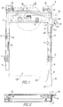
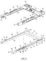
- the memory card and connector assembly of the present invention includes a frame member shown generally at numeral 10.
- This frame member is made up of a metallic rear transverse element 12 and two plastic longitudinal elements 14 and 16.
- the rear transverse element has metal extensions 18 and 20 which extend perpendicularly therefrom to be connected to the longitudinal elements by means of clips respectively at 22 and 24.
- On the longitudinal elements 14 and 16 there are also ESD contacts respectively at 26 and 28 and EMI contacts respectively at 30 and 32.
- front apertures respectively at 34 and 36 through these two longitudinal elements which with rear apertures 38 and 40 in the header as is explained below will be used to connect the assembly to a printed wiring board.
- There are also side grooves 42 and 44 in the two longitudinal elements which serve to retain the memory card between those elements.
- the spacer member includes longitudinal elements 52 and 54 which are positioned respectively beneath frame member longitudinal elements 14 and 16 and transverse member 55 which is positioned beneath transverse element 12 of the frame member so that the actuator bar and the longitudinal element 16 are generally in a common vertical plane P (Fig. 2).
- the spacer also has mounting apertures 56, 58, 60 and 62 which are aligned respectively with apertures 34, 36, 38 and 40 on the frame.
- the activator bar 48 is interposed between the longitudinal element 16 of the frame member and longitudinal element 54 of the spacer member.
- the activator bar is moveable longitudinally toward and away from the transverse element of the frame and includes a front pressure surface 64 for application of finger pressure to effect its movement toward the transverse member.
- the activator bar moves in an elongated groove 68 (Figs. 3-4) which is positioned between the longitudinal element 20 of the frame member and the longitudinal element 54 of the spacer member.
- this groove is formed as a result of a recess 70 on the upper surface 72 of the longitudinal element 54 which extends inwardly from the outer side 74 of longitudinal element 54 to an inner side wall 76.
- a fastener retaining member 78 Surrounding aperture 58 there is a fastener retaining member 78. Between this fastener retaining member 78 and inner side wall 76 there is a narrowed segment 80 of recess 70 through which a narrowed segment 82 of the activator bar 48 passes as the activator bar is moved in a forward and rearward longitudinal direction. When the actuator bar is in its rearward position, a front widened section 84 abuts against the fastener retainer member 78.
- a rear widened section 86 abuts against the fastener retainer member 78.
- a recess 88 on the upper surface 90 of the longitudinal element 52 which extends from the outer side (not shown) of longitudinal element 52 to an inner side wall 92.
- a fastener retaining member 94 Surrounding aperture 56 there is a fastener retaining member 94.
- a narrowed segment 96 of recess 88 Between recess 88 and longitudinal member 14 of the frame member another groove 98 (Fig. 3-4) is formed in which a second actuator bar (not shown) might optionally be mounted.
- a second frame member which is essentially similar in construction to frame member 10 might be positioned, for example, beneath spacer member 50 to form a double deck card connector assembly.
- a second actuator bar (not shown) having a downwardly and outwardly extending arm might be positioned to be longitudinally moveable in groove 98 to eject a card from that additional card connector.
- the activator bar is connected by means of an outwardly extending arm 100 an upwardly extending arm 102, an outwardly extending arm 104 and a terminal tab 106 to generally circularly shaped aperture 108 in arm 110.
- This arm 110 is connected by means of fulcrum pin 112 to the rear transverse element of the frame member and the card engagement plate positioned immediately beneath that rear transverse element.
- this arm has a recess 114 from which cam projection 116 extends.
- the memory card shown in phantom lines generally at 128 (only in Fig. 1) has a front end 130, a rear end 132 and opposed sides 134 and 136.
- the connector header is shown generally at numeral 138 and includes a transverse bar 140, front pins as at 142, rear pins as at 144 and opposed side legs 146 and 148.
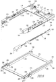
- the memory card and connector assembly of the present invention includes a frame member shown generally at numeral 210.
- This frame member is made up of a metallic rear transverse element 212 and two plastic longitudinal elements 214 and 216.
- the rear transverse element has metal extensions 218 and 220 which extend perpendicularly therefrom to be connected to the longitudinal elements by means of clips respectively at 222 and 224.
- There are also front apertures respectively at 234 and 236 through these two longitudinal elements which with rear apertures 238 and 240 in the header as is explained below will be used to connect the assembly to a printed wiring board.
- the spacer member has vertical apertures 256, 258, 260 and 262 which are aligned respectively with apertures 234, 236, 238 and 240 in the frame member in order to receive fasteners for fixing the frame member to the spacer member.
- the spacer member also includes front transverse member 263.
- the activator bar 248 is interposed between the longitudinal element 220 at the frame member and longitudinal element 254 of the spacer member.
- the activator bar is moveable longitudinally toward and away frame the transverse element of the frame and includes a front pressure surface 264 for application of finger pressure to effect its movement toward the transverse member.
- the activator bar moves in an elongated groove 268 (Fig. 7) which is positioned between the longitudinal element 220 of the frame member and the longitudinal element 254 of the spacer member.
- this groove is formed between an outer wall 274 and an inner wall 276 which extend upwardly from longitudinal element 254.
- a horizontal portion 280 of the activator bar is adjacent this fastener retaining member.
- a narrow, higher vertical section 282 is rearwardly positioned in groove 268.
- the outwardly curved section 284 abuts against the fastener retainer member 278.
- a fastener retaining member 294 Surrounding aperture 256 there is a fastener retaining member 294.
- a second frame member (not shown) which is essentially similar in construction to frame member 210 might be positioned, for example, beneath spacer member 250 to form a double deck card connector assembly.
- a second actuator bar (not shown) having a downwardly and outwardly extending arm might be positioned to be longitudinally moveable in groove 288 to eject a card from that additional card connector.
- the activator bar is connected by means of an outwardly extending arm 300 an upwardly extending arm 302 having a slot 304 to an outwardly extending arm 306, and a terminal tab 308 which extends from arm 310.
- This arm 310 is connected by means of fulcrum pin 312 to the rear transverse element of the frame member and the card engagement plate positioned immediately beneath that rear transverse element.
- the arm has an oblong aperture 314 through which cam projection 316 extends. This projection overlaps the projection 318 to allow it to move thereunder.
- the connector header is shown generally at numeral 338 and includes a transverse bar 340, front pins as at 342, rear pins as at 344 and opposed side legs 346 and 348.
Landscapes
- Physics & Mathematics (AREA)
- General Physics & Mathematics (AREA)
- Engineering & Computer Science (AREA)
- Theoretical Computer Science (AREA)
- Coupling Device And Connection With Printed Circuit (AREA)
- Details Of Connecting Devices For Male And Female Coupling (AREA)
Applications Claiming Priority (2)
| Application Number | Priority Date | Filing Date | Title |
|---|---|---|---|
| US624266 | 1984-06-25 | ||
| US08/624,266 US5863212A (en) | 1996-03-29 | 1996-03-29 | Memory card connector having reduced transverse dimension |
Publications (3)
| Publication Number | Publication Date |
|---|---|
| EP0798813A2 true EP0798813A2 (de) | 1997-10-01 |
| EP0798813A3 EP0798813A3 (de) | 1998-12-23 |
| EP0798813B1 EP0798813B1 (de) | 2002-01-09 |
Family
ID=24501303
Family Applications (1)
| Application Number | Title | Priority Date | Filing Date |
|---|---|---|---|
| EP97105260A Expired - Lifetime EP0798813B1 (de) | 1996-03-29 | 1997-03-27 | Speicherkartenverbinder mit reduzierter Querabmessung |
Country Status (7)
| Country | Link |
|---|---|
| US (1) | US5863212A (de) |
| EP (1) | EP0798813B1 (de) |
| JP (1) | JPH1027649A (de) |
| KR (1) | KR970068029A (de) |
| DE (1) | DE69709478T2 (de) |
| SG (1) | SG45541A1 (de) |
| TW (1) | TW326989U (de) |
Families Citing this family (12)
| Publication number | Priority date | Publication date | Assignee | Title |
|---|---|---|---|---|
| US7014118B1 (en) * | 1997-10-10 | 2006-03-21 | Robinson Nugent, Inc | Module header apparatus |
| TW360444U (en) * | 1997-10-20 | 1999-06-01 | Hon Hai Prec Ind Co Ltd | Card-withdrawing mechanism for electronic card connector |
| TW369224U (en) * | 1997-10-27 | 1999-09-01 | Hon Hai Prec Ind Co Ltd | Electronic card connector |
| JP3742564B2 (ja) * | 2001-04-05 | 2006-02-08 | 本多通信工業株式会社 | ポップアップ機構及びそれを備えたpcカード |
| JP4416968B2 (ja) * | 2001-07-30 | 2010-02-17 | キヤノン株式会社 | アダプタ |
| US6587350B1 (en) * | 2002-05-16 | 2003-07-01 | Inventec Corporation | Ejection mechanism for modular electronic element |
| US7561416B1 (en) * | 2006-12-15 | 2009-07-14 | Western Digital Technologies, Inc. | Storage device fixture with simultaneous unload mechanism |
| USD642578S1 (en) * | 2009-09-30 | 2011-08-02 | Sony Corporation | Memory card adapter |
| TWI372967B (en) * | 2010-03-15 | 2012-09-21 | Wistron Corp | Unloading mechanism for unloading an electronic component and computer device thereof |
| JP5699003B2 (ja) * | 2011-02-24 | 2015-04-08 | 日本航空電子工業株式会社 | コネクタ |
| JP5391251B2 (ja) * | 2011-09-30 | 2014-01-15 | 日本航空電子工業株式会社 | コネクタ |
| CN110875531B (zh) * | 2018-08-30 | 2021-08-20 | 富士康(昆山)电脑接插件有限公司 | 卡连接器及其凸轮杆 |
Family Cites Families (14)
| Publication number | Priority date | Publication date | Assignee | Title |
|---|---|---|---|---|
| JPS51134875A (en) * | 1975-05-19 | 1976-11-22 | Matsushita Electric Industrial Co Ltd | Method of manufacturing connector device for printed wiring board |
| JPH0541509Y2 (de) * | 1988-03-03 | 1993-10-20 | ||
| US5026296A (en) * | 1990-03-05 | 1991-06-25 | Japan Aviation Electronics Industry, Limited | Electrical connector equipped with release mechanism |
| JPH03297084A (ja) * | 1990-04-17 | 1991-12-27 | I T T Canon:Kk | エジェクタ付カードコネクタ |
| JP2521376Y2 (ja) * | 1990-08-31 | 1996-12-25 | デュポン アジア パシフィック リミテッド | Icパック用コネクタ装置 |
| JP2915609B2 (ja) * | 1991-03-25 | 1999-07-05 | オリンパス光学工業株式会社 | カード載置装置 |
| US5197894A (en) * | 1991-05-30 | 1993-03-30 | Japan Aviation Electronics Industry, Limited | Electrical connector equipped with a release mechanism |
| DE69117961T2 (de) * | 1991-12-16 | 1996-07-25 | Molex Inc | Auswurfsvorrichtung in einer Verbindervorrichtung für IC-Karten |
| JP2541694Y2 (ja) * | 1991-12-27 | 1997-07-16 | ケル株式会社 | 抜出機構付きメモリーカード用コネクタ |
| JP2621732B2 (ja) * | 1992-03-18 | 1997-06-18 | 富士通株式会社 | メモリカード用コネクタ |
| US5456610A (en) * | 1993-09-16 | 1995-10-10 | Molex Incorporated | Connector apparatus equipped with an ejector mechanism for IC packs |
| JP2544700B2 (ja) * | 1993-09-27 | 1996-10-16 | フォックスコン インタ−ナショナル インコ−ポレ−テッド | カ―ド型記憶媒体用コネクタ |
| JP3860230B2 (ja) * | 1993-11-19 | 2006-12-20 | バーグ・テクノロジー・インコーポレーテッド | データ処理媒体用コネクタ及びデータ処理媒体係止機構 |
| JPH07272793A (ja) * | 1994-03-10 | 1995-10-20 | Whitaker Corp:The | カードコネクタ及びそのカード排出機構 |
-
1996
- 1996-03-29 US US08/624,266 patent/US5863212A/en not_active Expired - Fee Related
-
1997
- 1997-03-18 TW TW086204149U patent/TW326989U/zh unknown
- 1997-03-27 EP EP97105260A patent/EP0798813B1/de not_active Expired - Lifetime
- 1997-03-27 DE DE69709478T patent/DE69709478T2/de not_active Expired - Fee Related
- 1997-03-28 KR KR1019970011198A patent/KR970068029A/ko not_active Ceased
- 1997-03-28 JP JP9078262A patent/JPH1027649A/ja active Pending
- 1997-03-29 SG SG1997001009A patent/SG45541A1/en unknown
Also Published As
| Publication number | Publication date |
|---|---|
| EP0798813B1 (de) | 2002-01-09 |
| TW326989U (en) | 1998-02-11 |
| JPH1027649A (ja) | 1998-01-27 |
| EP0798813A3 (de) | 1998-12-23 |
| SG45541A1 (en) | 1998-01-16 |
| DE69709478T2 (de) | 2002-11-07 |
| KR970068029A (ko) | 1997-10-13 |
| DE69709478D1 (de) | 2002-02-14 |
| US5863212A (en) | 1999-01-26 |
Similar Documents
| Publication | Publication Date | Title |
|---|---|---|
| JP3403098B2 (ja) | Icカード用コネクタ | |
| US6102716A (en) | PC card connector having improved resilient eject mechanism and method of use | |
| JP4018185B2 (ja) | コンタクトタイプのカードのための電気コネクタ | |
| US5421737A (en) | Universal ejector mechanism for an IC card connector apparatus | |
| US5451168A (en) | Connector apparatus for memory cards having a one-piece integrated frame | |
| US5730610A (en) | Memory card connector having a spring restrained activator rod and folding push button mechanism | |
| US5813878A (en) | Surface contact card connector | |
| US6544074B2 (en) | Electrical connector for smart card | |
| US6290136B1 (en) | Card ejection mechanism for PCMCIA connector | |
| EP0798813B1 (de) | Speicherkartenverbinder mit reduzierter Querabmessung | |
| US6609936B2 (en) | Smart card connector | |
| US6174197B1 (en) | Card connector assembly | |
| US6059588A (en) | Ejector mechanism for a card connector | |
| US8747163B2 (en) | Card connector assembly facilitating heat dissipation of inserted card | |
| US6478591B1 (en) | Card ejection mechanism for electrical card connector | |
| US5707245A (en) | Card connector with an ejection mechanism and a flexible printed circuit harness therefor | |
| US7946867B2 (en) | Card connector with a spring member for retaining an electrical card | |
| US6790061B1 (en) | Two-stage ejection mechanism of card connector | |
| US6799724B2 (en) | Card socket | |
| US6899555B2 (en) | Card connector | |
| US7341489B2 (en) | Electronic card connector | |
| EP0687036A2 (de) | Elektrische Stecker mit Ausziehvorrichtung | |
| US20060154528A1 (en) | Card connector | |
| US6097589A (en) | Shutter mechanism for electrode pad attached card and contact | |
| US6168446B1 (en) | Electronic card connector having an improved card release mechanism |
Legal Events
| Date | Code | Title | Description |
|---|---|---|---|
| PUAI | Public reference made under article 153(3) epc to a published international application that has entered the european phase |
Free format text: ORIGINAL CODE: 0009012 |
|
| AK | Designated contracting states |
Kind code of ref document: A2 Designated state(s): DE FR GB |
|
| PUAL | Search report despatched |
Free format text: ORIGINAL CODE: 0009013 |
|
| AK | Designated contracting states |
Kind code of ref document: A3 Designated state(s): DE FR GB |
|
| 17P | Request for examination filed |
Effective date: 19990505 |
|
| 17Q | First examination report despatched |
Effective date: 19990830 |
|
| GRAG | Despatch of communication of intention to grant |
Free format text: ORIGINAL CODE: EPIDOS AGRA |
|
| GRAG | Despatch of communication of intention to grant |
Free format text: ORIGINAL CODE: EPIDOS AGRA |
|
| GRAG | Despatch of communication of intention to grant |
Free format text: ORIGINAL CODE: EPIDOS AGRA |
|
| GRAH | Despatch of communication of intention to grant a patent |
Free format text: ORIGINAL CODE: EPIDOS IGRA |
|
| GRAH | Despatch of communication of intention to grant a patent |
Free format text: ORIGINAL CODE: EPIDOS IGRA |
|
| GRAA | (expected) grant |
Free format text: ORIGINAL CODE: 0009210 |
|
| REG | Reference to a national code |
Ref country code: GB Ref legal event code: IF02 |
|
| AK | Designated contracting states |
Kind code of ref document: B1 Designated state(s): DE FR GB |
|
| REF | Corresponds to: |
Ref document number: 69709478 Country of ref document: DE Date of ref document: 20020214 |
|
| ET | Fr: translation filed | ||
| PG25 | Lapsed in a contracting state [announced via postgrant information from national office to epo] |
Ref country code: GB Free format text: LAPSE BECAUSE OF NON-PAYMENT OF DUE FEES Effective date: 20020409 |
|
| PG25 | Lapsed in a contracting state [announced via postgrant information from national office to epo] |
Ref country code: DE Free format text: LAPSE BECAUSE OF NON-PAYMENT OF DUE FEES Effective date: 20021001 |
|
| PLBE | No opposition filed within time limit |
Free format text: ORIGINAL CODE: 0009261 |
|
| STAA | Information on the status of an ep patent application or granted ep patent |
Free format text: STATUS: NO OPPOSITION FILED WITHIN TIME LIMIT |
|
| GBPC | Gb: european patent ceased through non-payment of renewal fee |
Effective date: 20020409 |
|
| PG25 | Lapsed in a contracting state [announced via postgrant information from national office to epo] |
Ref country code: FR Free format text: LAPSE BECAUSE OF NON-PAYMENT OF DUE FEES Effective date: 20021129 |
|
| 26N | No opposition filed | ||
| REG | Reference to a national code |
Ref country code: FR Ref legal event code: ST |