EP0798820A2 - Douille, en particulier douille pour une lampe à vis ainsi que le procédé de fabrication d'une telle douille et le dispositif de mise en oeuvre de ce procédé - Google Patents
Douille, en particulier douille pour une lampe à vis ainsi que le procédé de fabrication d'une telle douille et le dispositif de mise en oeuvre de ce procédé Download PDFInfo
- Publication number
- EP0798820A2 EP0798820A2 EP97103085A EP97103085A EP0798820A2 EP 0798820 A2 EP0798820 A2 EP 0798820A2 EP 97103085 A EP97103085 A EP 97103085A EP 97103085 A EP97103085 A EP 97103085A EP 0798820 A2 EP0798820 A2 EP 0798820A2
- Authority
- EP
- European Patent Office
- Prior art keywords
- housing
- joining
- webs
- shells
- another
- Prior art date
- Legal status (The legal status is an assumption and is not a legal conclusion. Google has not performed a legal analysis and makes no representation as to the accuracy of the status listed.)
- Withdrawn
Links
Images




Classifications
-
- H—ELECTRICITY
- H01—ELECTRIC ELEMENTS
- H01R—ELECTRICALLY-CONDUCTIVE CONNECTIONS; STRUCTURAL ASSOCIATIONS OF A PLURALITY OF MUTUALLY-INSULATED ELECTRICAL CONNECTING ELEMENTS; COUPLING DEVICES; CURRENT COLLECTORS
- H01R43/00—Apparatus or processes specially adapted for manufacturing, assembling, maintaining, or repairing of line connectors or current collectors or for joining electric conductors
- H01R43/18—Apparatus or processes specially adapted for manufacturing, assembling, maintaining, or repairing of line connectors or current collectors or for joining electric conductors for manufacturing bases or cases for contact members
-
- H—ELECTRICITY
- H01—ELECTRIC ELEMENTS
- H01R—ELECTRICALLY-CONDUCTIVE CONNECTIONS; STRUCTURAL ASSOCIATIONS OF A PLURALITY OF MUTUALLY-INSULATED ELECTRICAL CONNECTING ELEMENTS; COUPLING DEVICES; CURRENT COLLECTORS
- H01R33/00—Coupling devices specially adapted for supporting apparatus and having one part acting as a holder providing support and electrical connection via a counterpart which is structurally associated with the apparatus, e.g. lamp holders; Separate parts thereof
- H01R33/05—Two-pole devices
- H01R33/22—Two-pole devices for screw type base, e.g. for lamp
-
- H—ELECTRICITY
- H01—ELECTRIC ELEMENTS
- H01R—ELECTRICALLY-CONDUCTIVE CONNECTIONS; STRUCTURAL ASSOCIATIONS OF A PLURALITY OF MUTUALLY-INSULATED ELECTRICAL CONNECTING ELEMENTS; COUPLING DEVICES; CURRENT COLLECTORS
- H01R13/00—Details of coupling devices of the kinds covered by groups H01R12/70 or H01R24/00 - H01R33/00
- H01R13/46—Bases; Cases
- H01R13/502—Bases; Cases composed of different pieces
- H01R13/504—Bases; Cases composed of different pieces different pieces being moulded, cemented, welded, e.g. ultrasonic welding, or swaged together
Definitions
- the invention relates to a housing, in particular a socket housing for incandescent lamps with a screw base with the features from the preamble of claim 1.
- the invention further relates to a method for producing such a housing and devices for carrying out the method.
- a socket housing for a lamp with the features from the preamble of claim 1 is described in EP 0 612 122 A2.
- the invention has for its object to provide a housing in which the half-shells to be connected are designed so that ultrasonic welding is practically possible and to provide a method by which this ultrasonic welding can be carried out in a simple and permanent manner. Furthermore, devices for carrying out the method should be created.
- a method for producing the housing according to the invention is the subject of claim 23. Further developments of the method are described in claims 24 and 25.
- Semi-crystalline thermoplastics eg PBTP, PETP or PA 6.6
- PBTP, PETP or PA 6.6 Semi-crystalline thermoplastics
- PA 6.6 Semi-crystalline thermoplastics
- Such semi-crystalline thermoplastics can only be welded in the far field with restrictions.
- the basic idea of the invention is to arrange the joining surfaces on the two half-shells that compose the housing in such a way that the ultrasound energy can be supplied, which ensures welding in the near field. Furthermore, stop surfaces interacting on the two half-shells are arranged outside of the joining zones, which abut against one another when the housing is assembled before welding and ensure that the half-shells are fixed in the position in which they are to be welded to one another. A rapid and permanent ultrasonic welding of the half shells that make up the housing can thus be achieved in a simple, easily automatable process. To carry out this method, the invention provides a number of simply constructed devices.
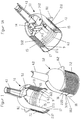
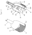
- FIG. 1 to 4 show a lamp holder housing for a lamp, as it can be used for example for pendant lamps.
- the housing which consists of a partially crystalline thermoplastic, is essentially axially symmetrical with respect to the housing axis S and is composed of two half-shells 1.1 and 1.2, which are designed such that the housing in its in Fig 1 and 2 lower section is designed as an open hollow cylinder, the base of a lamp being insertable through the open end of the hollow cylinder in the finished state of the housing.
- the two half-shells 1.1 and 1.2 are designed so that the parting plane between the half-shells, that is, the plane in which the mutually opposite edge sections of the two half-shells lie in the assembled state, is an axial longitudinal plane in which the housing axis S lies.
- the two half-shells 1.1 and 1.2 have, in a manner known per se, parts 4.1 and 4.2, which complement one another when assembled to form an insertion grommet for a supply cable, and parts 5.1 and 5.2, which complement one another for holding devices for a contact carrier 14, parts 6.1 and 6.2 which complement each other to form a lamp support thread, parts 7.1 and 7.2 which complement each other to an external thread and parts 8.1 and 8.2 which complement each other to form an outer flange with stops for a lampshade.
- Flat webs 2.11, 2.12 and 2.21, 2.22 are arranged on the edges of the half-shells which are opposite one another when the two half-shells 1.1 and 1.2 are attached. When the two half-shells are put together, these webs get into an overlapping mutual position, so that, for example, webs 2.11 and 2.12 are on the outside and webs 2.21 and 2.22 are on the inside of the housing. At least the sections of the webs lying in the cylindrical section of the housing are to be welded to one another in a predetermined length during the subsequent ultrasonic welding.
- the surfaces to be welded to one another on the webs are referred to as "joining surfaces" and the area in which the joining surfaces lie opposite one another is referred to as the "joining zone”.
- stop surfaces are arranged outside the joining zones, which run parallel to the parting plane and perpendicular to the joining surfaces and in the assembled state of the housing abut each other.
- stop faces are given in the half-shell 1.1 by the end faces 15 of the webs 2.11 and 2.12, which in the assembled state rest against stop faces which are given by the end faces 16 on the edges of the external thread section 7.2.
- the lamp support thread in the area of the overlapping parts is composed of parts 6.1 and 6.2, which are formed from parts integrally connected to the housing, projecting inwards and extending at an angle to the circumferential direction the webs 2.11, 2.12 or 2.21, 2.22 interrupted.
- parts 7.1 and 7.2, which complement the external thread, and parts 8.1 and 8.2, which complement the external flange, are interrupted in the area of the webs.
- the contact carrier 14 (see FIG.
- 1 to 4 are arranged on the inside of the projections 2.11 and 2.12 joining surfaces 3.11 and 3.12 and on the outside of the projections 2.21 and 2.22 joining surfaces 3.21 and 3.22.
- these joining surfaces run essentially perpendicular to the parting plane between the two half-shells and in their longitudinal direction parallel to the axial direction S of the housing.
- the joining zones which are each formed from the joining surface pairs 3.11 and 3.21 or 3.12 and 3.22, are arranged on the half-shells symmetrically to the housing axis S.
- the joining surfaces through which the ultrasonic energy emerges during the ultrasonic welding described below in order to enter the respectively opposite joining surface are provided in a manner known per se with energy direction sensors which are rib-like with an essentially triangular cross section.
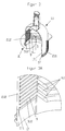
- the energy direction indicators 9 are each located on the joining surfaces 3.11 and 3.12 (see FIGS. 3A and 4A).
- the energy direction sensors 9 run transversely to the longitudinal direction of the joining surfaces and perpendicular to the parting plane.
- the width of the webs is greater than or equal to 1/6 of the housing diameter and the thickness of the webs is less than 1/5 of their width. It is also advantageous if the dimensions of the webs are selected and the webs are designed to be elastic in such a way that the half-shells 1.1 and 1.2 are pressed together after assembly and before welding.
- the webs 2.11 and 2.12 or 2.21 and 2.22 are essentially flat, so that the mutually opposite joining surfaces and the surfaces to which sonotrodes or anvil parts are attached are flat surfaces. It has now been found that it is favorable and desirable if in a section of predetermined axial length adjoining the opening edge of the socket housing, the inner and outer side surfaces of the webs are cylindrical surface sections. With this configuration, the distance between the opening edge and a screwed-in incandescent lamp can be kept at a uniformly low value over the circumference. The distance must not exceed a predetermined value in order not to impair the protection against contact when inserting an incandescent lamp.
- this distance must not be less than another predetermined value, because otherwise there is a risk that the socket rim will damage the glass bulb of an incandescent lamp when unscrewing it.
- this is solved in such a way that the webs 2.11 and 2.12 on the half-shell 1.1 have a cylindrical surface section 17 and the webs 2.21 and 2.22 on the half-shell 1.2 have a cylindrical surface section 18, each of which begins at the housing opening and extends over a predetermined part of the Bridge length extends.
- each cylinder surface section 17 and 18 merges at a predetermined point 17.1 or 18.1 into a flat section on which the actual joining surfaces 3.11, 3.12 or 3.21, 3.22 are arranged.
- the two half-shells 1.1 and 1.2 are not welded to one another in the area of the cylindrical surface sections 17 and 18.
- the cylindrical surface sections 17 are also provided with the energy direction sensors 9 shown in FIGS. 1 and 1A and arranged on the joining surfaces 3.11 and 3.12.
- the external thread section 7.1 can be guided in the region of the cylindrical surface section 17 up to the edge of the webs 2.11 or 2.12.
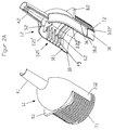
- FIGS. 1 to 4 shows a variant of the embodiment of a lamp housing according to FIGS. 1 to 4, which differs from the embodiment described above only in that in the case of a half shell 1.2 instead of the webs 2.21 or 2.22, wall sections 2.21 'or 2.22 'occur, each consisting of a web, on the outside of which the joining surface 3.21' or 3.22 'is arranged, while on the side facing away from the joining surface there are radial ribs 19 running perpendicular to the parting plane.
- the other half-shell 1.1 is formed in this embodiment, as shown in FIGS. 1 and 1A.
- the wall sections 2.21 'and 2.22' are accordingly overlapped by the webs 2.11 and 2.12 in such a way that the joining surfaces 3.11 and 3.21 'and 3.12 and 3.22' lie opposite one another. Since the embodiment according to FIG. 2A corresponds in its remaining features to the embodiment according to FIGS. 1, 1A and 2, these parts have the same reference numerals as in this embodiment and will not be described again.
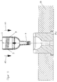
- FIG. 5 to 8 show a first device with a mounting block 10, in which an insert 10.1 is inserted, which is designed to receive the supply end of a socket housing 1, which is composed in the manner already described from two half-shells in a light press fit and in The illustrated embodiment is inserted from above in the direction of arrow A1 into the mounting block 10 in such a way that the inlet grommet 4 engages in the insert 10.1 and the open end of the housing 1 is directed axially upward.
- the joining zones between the two half-shells are designated by reference number 3.
- the device also has two anvil parts 11 and 12 which are symmetrically opposite one another with respect to the direction of the housing axis S and can be moved towards one another in the radial direction. As can be seen from FIG.
- the housing 1 inserted into the mounting block 10 lies between the two anvil parts 11 and 12, which can be moved towards one another in the directions R1.
- a sonotrode 13 of an ultrasound welding device which is otherwise not shown, and which can be inserted into the interior of the housing through the open end of the housing 1 in the axial direction A2.
- the sonotrode 13 is designed such that it lies against the inside of the housing in the region of the joining zones 3, which is ensured in the exemplary embodiment shown that the sonotrode 13 in the radial directions in which the joining zones 3 of the housing 1 are arranged, has an outer diameter which is essentially corresponds to the inside diameter of the housing 1.
- the ultrasonic welding process can be initiated.
- the vibration amplitude is in the direction of US1 and the ultrasonic energy is conducted directly into the joining zones 3 in the near field.
- the mutually opposite joining zones 3 can thus be welded together at the same time.
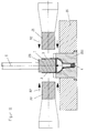
- the device has a mounting block 20 with an insert 20.1, which is adapted to the supply side of the housing 1.
- the housing 1 in turn consists of two half-shells assembled in a light press fit as described above and is inserted in the axial direction A3 in the mounting block 20 so that the feed grommet 4 is received by the insert part 20.1.
- an anvil part 23 is then lowered from above in the axial direction A4 and, as can be seen from FIG. 11, inserted into the interior of the housing.
- This anvil part 23 lies in the radial directions in which the joining zones 3 of the housing lie, to the inside wall of the housing.
- the anvil part 23 has an outer diameter in the radial direction in which the joining zones 3 are arranged, which essentially corresponds to the inner diameter of the housing 1.
- the device furthermore has two sonotrodes 21 and 22 which are arranged symmetrically opposite one another with respect to the direction of the housing axis S and can be moved towards one another in the radial direction R2 and which, as can be seen from FIG. lay on the outside of the housing 1.
- the ultrasonic welding process is initiated.
- the vibration amplitudes are in the direction of US2 and US3.
- the ultrasonic energy arrives directly in the joining zones 3, so that near-field welding is also ensured here and the two joining zones can be welded simultaneously.
Landscapes
- Engineering & Computer Science (AREA)
- Manufacturing & Machinery (AREA)
- Lining Or Joining Of Plastics Or The Like (AREA)
Applications Claiming Priority (2)
| Application Number | Priority Date | Filing Date | Title |
|---|---|---|---|
| DE19612279 | 1996-03-28 | ||
| DE1996112279 DE19612279C2 (de) | 1996-03-28 | 1996-03-28 | Gehäuse, insbesondere Fassungsgehäuse für Glühlampen mit Schraubsockel sowie Verfahren zur Herstellung eines derartigen Gehäuses und Vorrichtungen zur Durchführung des Verfahrens |
Publications (2)
| Publication Number | Publication Date |
|---|---|
| EP0798820A2 true EP0798820A2 (fr) | 1997-10-01 |
| EP0798820A3 EP0798820A3 (fr) | 1998-12-16 |
Family
ID=7789685
Family Applications (1)
| Application Number | Title | Priority Date | Filing Date |
|---|---|---|---|
| EP97103085A Withdrawn EP0798820A3 (fr) | 1996-03-28 | 1997-02-26 | Douille, en particulier douille pour une lampe à vis ainsi que le procédé de fabrication d'une telle douille et le dispositif de mise en oeuvre de ce procédé |
Country Status (2)
| Country | Link |
|---|---|
| EP (1) | EP0798820A3 (fr) |
| DE (1) | DE19612279C2 (fr) |
Cited By (3)
| Publication number | Priority date | Publication date | Assignee | Title |
|---|---|---|---|---|
| WO2002013587A3 (fr) * | 2000-08-09 | 2002-03-21 | Schefenacker Lighting Systems | Boitier en deux parties muni d'un cable qui traverse les surfaces d'assemblage |
| ITMI20111306A1 (it) * | 2011-07-14 | 2013-01-15 | Arditi Spa | Portalampada, particolarmente per lampade con attacco filettato, ad elevata semplicita' di assemblaggio. |
| ITMI20121779A1 (it) * | 2012-10-22 | 2014-04-23 | Arditi Spa | Portalampada, particolarmente per lampade con attacco filettato, ad elevata semplicita' di assemblaggio. |
Families Citing this family (3)
| Publication number | Priority date | Publication date | Assignee | Title |
|---|---|---|---|---|
| DE19812142A1 (de) * | 1998-03-20 | 1999-09-23 | Walter Holzer | Lampenfassung |
| DE19909695C2 (de) * | 1999-03-05 | 2001-04-05 | Helgo Schmidt | Zweigeteilte Glühbirnenfassung |
| DE102024105677B4 (de) * | 2024-02-28 | 2025-11-27 | Lumberg Connect Gmbh | Steckverbinder |
Family Cites Families (5)
| Publication number | Priority date | Publication date | Assignee | Title |
|---|---|---|---|---|
| US3600534A (en) * | 1970-08-21 | 1971-08-17 | Sternco Ind Inc | Electric socket switch |
| DE2259860A1 (de) * | 1971-12-09 | 1973-06-14 | Deutsher Pty Ltd | Lampenfassung |
| US4184734A (en) * | 1977-05-03 | 1980-01-22 | Ab Coripen | Lampholder |
| AT358270B (de) * | 1977-07-12 | 1980-08-25 | Kapsch Telephon Telegraph | Verfahren und vorrichtung zum dichten ver- schweissen eines behaeltermantels aus thermoplastischem kunststoff mit einem boden- oder deckelteil aus thermoplastischem kunst- stoff mit hilfe von ultraschall |
| IT1265840B1 (it) * | 1993-02-15 | 1996-12-12 | Luca Rossignoli | Sistema per realizzare porta-lampade con virola a "frutto" interno incorporato. |
-
1996
- 1996-03-28 DE DE1996112279 patent/DE19612279C2/de not_active Expired - Fee Related
-
1997
- 1997-02-26 EP EP97103085A patent/EP0798820A3/fr not_active Withdrawn
Cited By (3)
| Publication number | Priority date | Publication date | Assignee | Title |
|---|---|---|---|---|
| WO2002013587A3 (fr) * | 2000-08-09 | 2002-03-21 | Schefenacker Lighting Systems | Boitier en deux parties muni d'un cable qui traverse les surfaces d'assemblage |
| ITMI20111306A1 (it) * | 2011-07-14 | 2013-01-15 | Arditi Spa | Portalampada, particolarmente per lampade con attacco filettato, ad elevata semplicita' di assemblaggio. |
| ITMI20121779A1 (it) * | 2012-10-22 | 2014-04-23 | Arditi Spa | Portalampada, particolarmente per lampade con attacco filettato, ad elevata semplicita' di assemblaggio. |
Also Published As
| Publication number | Publication date |
|---|---|
| DE19612279A1 (de) | 1997-10-02 |
| EP0798820A3 (fr) | 1998-12-16 |
| DE19612279C2 (de) | 1998-07-09 |
Similar Documents
| Publication | Publication Date | Title |
|---|---|---|
| DE2922705C2 (de) | Verbinder für optische Fasern | |
| EP0653025B1 (fr) | Goujon a souder, dispositif de soudage pour souder un element de fixation et procede de fixer une piece de montage sur un element de fixation | |
| EP0170844B1 (fr) | Pièce de piquage en matière plastique soudable | |
| DE3803586C2 (de) | Elektrischer Rauschabsorber | |
| DE19922666C2 (de) | Kabeldurchführung | |
| DE102007014049B3 (de) | Ausgleichselement zum Verbinden von Bauteilen | |
| DE3246327A1 (de) | Vorrichtung zur verbindung zweier rohrenden | |
| EP1154875B2 (fr) | Procede d'assemblage de deux pieces d'un siege de vehicule | |
| EP0332759A2 (fr) | Dispositif de fixation axiale pour la connexion d'éléments tubulaires | |
| EP2769830B2 (fr) | Sonotrode ronde | |
| DE69201061T2 (de) | Rohrabsperrvorrichtung. | |
| DE3342302A1 (de) | Verfahren zur herstellung einer kleinstsicherung sowie kleinstsicherung | |
| EP0240732B1 (fr) | Elément de soudage pour le soudage bout à bout de tuyaux en matière plastique | |
| DE102008055518A1 (de) | Verbindungsstück | |
| DE19612279C2 (de) | Gehäuse, insbesondere Fassungsgehäuse für Glühlampen mit Schraubsockel sowie Verfahren zur Herstellung eines derartigen Gehäuses und Vorrichtungen zur Durchführung des Verfahrens | |
| DE102011102624B4 (de) | Halteelement und Halteanordnung zum Halten einer Sicherung sowie Sicherungssystem | |
| EP0711948B1 (fr) | Manchon à souder pour connexion de parties tubulaires de la matière plastique | |
| DE2730217A1 (de) | Rohrverbindung | |
| DE29609435U1 (de) | Verschluß für ein Entleerungsrohr | |
| DE69425638T2 (de) | Ansatzstück für eine Verschleisserfassungseinrichtung eines Bremsbelages | |
| DE19927778C1 (de) | Schweißmuffe | |
| DE10107465C1 (de) | Steckverbindung für Rohrleitungen | |
| DE19960585A1 (de) | Heizvorrichtung mit unterteiltem Mantelrohr | |
| EP0612122A2 (fr) | Système pour la réalisation de douilles de lampe avec socle avec insert interne incorporé | |
| DE1297178B (de) | Werkzeug zum Ausbauen elektrischer Kontakte aus einer Leitungskupplung |
Legal Events
| Date | Code | Title | Description |
|---|---|---|---|
| PUAI | Public reference made under article 153(3) epc to a published international application that has entered the european phase |
Free format text: ORIGINAL CODE: 0009012 |
|
| AK | Designated contracting states |
Kind code of ref document: A2 Designated state(s): BE DE FR IT |
|
| PUAL | Search report despatched |
Free format text: ORIGINAL CODE: 0009013 |
|
| AK | Designated contracting states |
Kind code of ref document: A3 Designated state(s): BE DE FR IT |
|
| 17P | Request for examination filed |
Effective date: 19990610 |
|
| 17Q | First examination report despatched |
Effective date: 20001016 |
|
| RTI1 | Title (correction) |
Free format text: SCREW TYPE LAMP SOCKET BASE, MANUFACTURING PROCESS OF SUCH A BASE AND APPARATUS FOR THIS MANUFACTURING PROCESS |
|
| GRAG | Despatch of communication of intention to grant |
Free format text: ORIGINAL CODE: EPIDOS AGRA |
|
| GRAG | Despatch of communication of intention to grant |
Free format text: ORIGINAL CODE: EPIDOS AGRA |
|
| GRAG | Despatch of communication of intention to grant |
Free format text: ORIGINAL CODE: EPIDOS AGRA |
|
| GRAH | Despatch of communication of intention to grant a patent |
Free format text: ORIGINAL CODE: EPIDOS IGRA |
|
| STAA | Information on the status of an ep patent application or granted ep patent |
Free format text: STATUS: THE APPLICATION IS DEEMED TO BE WITHDRAWN |
|
| 18D | Application deemed to be withdrawn |
Effective date: 20020817 |