EP0798935A2 - Système de projection en deux étapes - Google Patents
Système de projection en deux étapes Download PDFInfo
- Publication number
- EP0798935A2 EP0798935A2 EP97301847A EP97301847A EP0798935A2 EP 0798935 A2 EP0798935 A2 EP 0798935A2 EP 97301847 A EP97301847 A EP 97301847A EP 97301847 A EP97301847 A EP 97301847A EP 0798935 A2 EP0798935 A2 EP 0798935A2
- Authority
- EP
- European Patent Office
- Prior art keywords
- module
- relay system
- radiation
- further characterized
- spectral
- Prior art date
- Legal status (The legal status is an assumption and is not a legal conclusion. Google has not performed a legal analysis and makes no representation as to the accuracy of the status listed.)
- Granted
Links
Images


Classifications
-
- H—ELECTRICITY
- H04—ELECTRIC COMMUNICATION TECHNIQUE
- H04N—PICTORIAL COMMUNICATION, e.g. TELEVISION
- H04N9/00—Details of colour television systems
- H04N9/12—Picture reproducers
- H04N9/31—Projection devices for colour picture display, e.g. using electronic spatial light modulators [ESLM]
- H04N9/3102—Projection devices for colour picture display, e.g. using electronic spatial light modulators [ESLM] using two-dimensional electronic spatial light modulators
- H04N9/3105—Projection devices for colour picture display, e.g. using electronic spatial light modulators [ESLM] using two-dimensional electronic spatial light modulators for displaying all colours simultaneously, e.g. by using two or more electronic spatial light modulators
Definitions
- This invention relates to full color projection systems, and more particularly to high efficiency, high performance systems including a one-to-one relay and a refractive projection lens system.
- the purpose of this invention is to greatly simplify a very high brightness, high performance projection system.
- a system constructed according to the invention has a single output. Therefore, the color convergence is easy to control and the image is very sharp. Additionally, the system is suitable for implementation of a zoom configuration with external exit pupil to further enhance application versatility.
- an exemplary embodiment of the invention is a two-stage full color, image combining projection system, comprising a one-to-one relay system for combining radiation from long and short spectral band image sources, e.g. blue and red, and a combining projector.
- the relay system includes a spectral combining module to combine the radiation from the long and short spectral band image sources, a spherical primary module and a secondary spherical module.
- the combining projector includes a beam combiner and a projection optics system.
- the spherical primary module reflects the combined radiation from the spectral combining module onto the spherical secondary module. This combined radiation in turn reflects off the secondary module back onto the primary module, the primary module in turn focussing the combined radiation reflected off the secondary module at the beam combiner.
- the beam combiner combines the combined radiation from the spectral combining module with radiation from a third image source providing radiation in a band, e.g. green, intermediate the long and short bands to provide a full color combined image.
- the preferred embodiment of the spectral combining module includes an X-prism.
- the spherical primary module includes a spherical mirror.
- the spherical secondary module includes a convex mirror and an axial chromatic correction element for compensating chromatic aberration introduced by the spectral combining module.
- FIG. 1 is an optical schematic diagram of a two-stage image combining projection system embodying the invention.
- FIG. 2a is a schematic diagram of a first embodiment of the one-to-one relay comprisinq the system of FIG. 1, the relay including a zero power doublet.
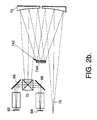
- FIG. 2b is a schematic diagram of a second embodiment of the one-to-one relay comprising the system of FIG. 1, the relay including a diffraction optical element.
- FIG. 3 is an optical schematic of a first embodiment of the second stage of the projection system of FIG. 1, the second stage including a refractive projector with a polarization beam splitter cube.
- FIG. 4 is an optical schematic of a second embodiment of the second stage of the projection system of FIG. 1, the second stage including a zoom projector with a polarization beam splitter cube.
- FIG. 5 is an optical schematic of a second embodiment of the second stage of the projection system of FIG. 1, the second stage including a reflective projector with a polarization beam splitter cube.
- FIG. 6 is an optical schematic of a further alternate embodiment, wherein an X-prism directly combines radiation from the red, blue and green image sources.
- FIG. 1 is a simplified optical schematic diagram of a two-staging image combining projector 50 in accordance with the invention, wherein the first stage 60 includes an improved Offner's one-to-one relay system, and the second stage 100 is a beam combining projector.
- the radiation from color 1 and 2 image sources 62 and 64 (such as blue and red liquid crystal light valves (LCLV) are first reflected by mirrors 66 and 68 onto and combined through an X-prism 70.
- the prism 70 has beam splitting surfaces 70A and 70B respectively coated with band pass filters.
- the coated surface 70B reflects the blue radiation and transmits the red radiation
- the surface 70A reflects the red radiation and transmits the blue radiation.
- the combined images are then reflected off the primary spherical mirror 72 and directed to secondary assembly 74, and finally focused by the primary mirror 72 again to form a one-to-one relayed two-color image indicated generally as beam 76, which is directed by mirror 80 into the second stage 100.
- the projector 50 forms an identically sized and inverted image of the combined blue and red image sources, and is therefore called a one-no-one relay.
- the two-color image 76 is further combined with the radiation from color 3 image source 102, e.g. a green LCLV, through a polarization beam splitter cube 104 located between the third image source 102 and the refractive projector 110.
- the combined 3-color radiation indicated as beam 106 is projected out through the refractive projector 110 as the output beam indicated as beam 120.
- the advantages associated with a two-staging image combining projector in accordance with the invention include (i) very high brightness as a result of high combining efficiency, (ii) a very long back focal distance in the one-to-one relay module makes the package very flexible, (iii) capability of implementing a zoom function, which is necessary in many application, and (iv) a capability of external exit pupil makes the projector very versatile for interfacing other optical modules.
- a conventional Offner relay consists of only the primary and the secondary mirrors.
- the incorporation of the X-prism in the optical system in accordance with the invention introduces spherical and chromatic aberrations which the conventional Offner relay would be unable to correct.
- the one-to-one relay 60 includes three modules, a spherical primary 72, a spherical secondary module 74, and a spectral combining module 70. In comparison to conventional Offner designs, the present invention provides additional capabilities.
- An X-prism 70 combines the radiation for both the long and short spectral bands, i.e. the red and blue spectral bands. Although capable of merging radiation from three different LCLVs as described below with respect to FIG. 6, an X-prism combining only the long and short spectral band radiation reflected off the hypotenuses 70A and 70B of the X-prism 70 has much better efficiency.
- the secondary assembly 74 includes a convex mirror 74A and an axial chromatic correction element such as a zero power doublet 740 shown in FIG. 2a, in front of the secondary mirror 74A, or a diffractive optical element (DOE) 742 shown in simplified schematic form in FIG. 2b on the mirror 74A.
- This additional chromatic aberration correction mechanism is very important for compensating the chromatic aberration introduced by the beam combining X-prism 70.
- the zero power doublet 740 comprises one lens with high Abbe number (such as BK7, SK16) and one lens with low Abbe number (such as F2, SF11). While maintaining zero total optical power, various amounts of the chromatic aberration can be generated by varying the optical power of each lens. For instance, the chromatic aberration of a SK16-F2 zero power doublet with a 1.0 and -1.0 optical power for the SK16 and F2 lenses, respectively, is different from that of a 0.9 and -0.9 optical power of the Sk16-F2 doublet.
- the chromatic aberration can also be corrected by a DOE 742 (FIG. 2b) with a very small amount of diffractive power.
- the structure of a DOE suitable for the purpose is shown in FIG. 3 of commonly assigned U.S. Patent 5,257,133, entitled RE-IMAGING OPTICAL SYSTEM EMPLOYING REFRACTIVE AND DIFFRACTIVE OPTICAL ELEMENTS.
- the second stage combining projector 100 includes a beam combiner 104 and a projection optics system 110.
- a polarization beam combiner is preferred as the beam combiner 104 for LCLV image sources due to its better combining efficiency.
- a polarization beam combiner is generally arranged in such a way that the S-polarization radiation is reflected off the beam combining surface 104A and the P-polarization is transmitted through the beam combining surface.
- the phase of the combined blue and red image from the one-to-one relay is a function of the projection image brightness. To display a bright red or blue pixel on the screen, the phase of the corresponding radiation of the combined image is S-polarized so that it is totally reflected off the beam combining surface 104A.
- the phase of the corresponding radiation of a dark image pixel is P-polarized. Therefore, it is totally transmitted through the polarization beam combiner surface 104A.
- the gray level of the image is obtained by rotating the phase of the radiation between the S and the P polarization.
- An LCLV is the preferred mechanism for rotating the phase of the radiation.
- a half-wave plate 104B in front of the polarization beam combiner 104 rotates the radiation by 90 degrees. Therefore, the S-polarization from the green LCLV source 102 is rotated to P-polarization by plate 104B and totally transmitted through the polarization cube 104.
- the projection optics system 110 can be refractive or reflective, with either fixed focal length (FFL) or variable focal length (VFL).
- FIG. 3 illustrates a typical example of a FFL refractive projector 110A, which includes optical elements 1102-1112.
- the projector has to be telecentric (i.e. the principle rays are parallel to the optical axis) in the LCLV space.
- the back focal distance of the projector has also to be long enough to accommodate the physical sizes of the LCLV module 102 and the polarization combining cube 104.
- the doublets 1102-1104 and 1106-1108 perform these two functions, i.e. providing the telecentric and the long back focal distance.
- the optical power of the entire projector is mainly provided by these two doublets.
- the doublet 1110-1112 compensates the chromatic aberration generated by the polarization beam combiner and the doublets 1102-1104 and 1106-1108.
- the output combined image 120 is afocal (the image is focused ad infinite, i.e. the output beam is collimated) and ready for coupling with fore optics (the optics in front of the rest of the optical system).
- the refractive projector can be finite conjugate for projecting the image on a screen; i.e. the object and image position are not located at infinite. Usually, if the object or image distance is larger than ten times the focal length of the system, the object or image is considered to be at infinity. So, the projector 110A is an afocal system in the projection space.
- FIG. 4 shows a typical example of a VFL refractive projector 110B, which includes optical elements 1120-1144.
- the VFL projector has four lens groups, the prime group (lens 1120-1126), the compensator group (1128-1132), the variator group (1134-1138), and the collimator group (1140-1144).
- the variator is the key group providing most of the zooming capability.
- the compensator provides for the rocus compensation such that the image remains sharp.
- the combination of the prime, compensator and variator relays the combined images (i.e. the blue, green and red images) to where the collimator can project the combined image onto the screen. This capability is particularly important for many simulator and commercial applications.
- FIG. 5 shows an exemplary FFL reflective projector 110C, comprising mirrors 1150, 1152 and 1154.
- the three mirror projector is similar in operation to a three mirror telescope with the combined image coinciding with the image plane of the telescope.
- the advantage associated with the reflective projector 110C is its freedom from chromatic aberration.
- the projector can therefore project both visible and IR images.
- a reflective projector makes the system very simple.
- the potential applications include a near infrared simulator for night vision goggle applications or an infrared simulator operating at the infrared spectral range.
- the image sources 62, 64 and 102 could operate, for example, respectively at 0.75 micron, 0.85 micron and 1.06 micron.
- FIG. 6 shows a further alternate embodiment of a projection system embodying aspects of the invention.
- the X-prism 70 combines the red, blue and green image radiation from respective sources 62, 64 and 102. While this embodiment does not provide the same high combining efficiency as the embodiment of FIG. 1, it also is somewhat simpler, since a polarization beam splitter cube 104 is not needed.
- This embodiment also employs the primary mirror 72 and the secondary assembly 74 as in the embodiment of FIG. 1.
- the combined radiation is focused at a reticle 130, and may be passed through projection optics similar to optics 110, if need for the particular application.
Landscapes
- Engineering & Computer Science (AREA)
- Multimedia (AREA)
- Signal Processing (AREA)
- Lenses (AREA)
- Projection Apparatus (AREA)
- Optical Elements Other Than Lenses (AREA)
Applications Claiming Priority (2)
| Application Number | Priority Date | Filing Date | Title |
|---|---|---|---|
| US623493 | 1996-03-28 | ||
| US08/623,493 US5677788A (en) | 1996-03-28 | 1996-03-28 | Two-stage projection system |
Publications (3)
| Publication Number | Publication Date |
|---|---|
| EP0798935A2 true EP0798935A2 (fr) | 1997-10-01 |
| EP0798935A3 EP0798935A3 (fr) | 1998-01-07 |
| EP0798935B1 EP0798935B1 (fr) | 2002-01-16 |
Family
ID=24498283
Family Applications (1)
| Application Number | Title | Priority Date | Filing Date |
|---|---|---|---|
| EP97301847A Expired - Lifetime EP0798935B1 (fr) | 1996-03-28 | 1997-03-19 | Système de projection en deux étapes |
Country Status (5)
| Country | Link |
|---|---|
| US (1) | US5677788A (fr) |
| EP (1) | EP0798935B1 (fr) |
| JP (1) | JP2818591B2 (fr) |
| CA (1) | CA2198961C (fr) |
| DE (1) | DE69709562T2 (fr) |
Cited By (4)
| Publication number | Priority date | Publication date | Assignee | Title |
|---|---|---|---|---|
| WO2001011425A1 (fr) * | 1999-08-04 | 2001-02-15 | Sanyo Electric Co., Ltd. | Dispositif de projection de type retroprojecteur |
| EP1075150A3 (fr) * | 1999-07-31 | 2005-04-27 | Lg Electronics Inc. | Système de lentilles de projection |
| EP1454186A4 (fr) * | 2001-11-30 | 2006-01-18 | Silicon Light Machines Inc | Dispositif d'affichage comprenant un melangeur de couleurs rgb et un relais a modulateurs de lumiere 1d avec filtre de strioscopie |
| WO2006036306A1 (fr) * | 2004-09-15 | 2006-04-06 | Hewlett-Packard Development Company, L.P. | Relais optique |
Families Citing this family (9)
| Publication number | Priority date | Publication date | Assignee | Title |
|---|---|---|---|---|
| US6292713B1 (en) | 1999-05-20 | 2001-09-18 | Compaq Computer Corporation | Robotic telepresence system |
| US6781606B2 (en) | 1999-05-20 | 2004-08-24 | Hewlett-Packard Development Company, L.P. | System and method for displaying images using foveal video |
| US6346950B1 (en) | 1999-05-20 | 2002-02-12 | Compaq Computer Corporation | System and method for display images using anamorphic video |
| KR100440958B1 (ko) * | 2001-10-12 | 2004-07-21 | 삼성전자주식회사 | 조명계 및 이를 채용한 프로젝터 |
| KR100440959B1 (ko) * | 2001-11-08 | 2004-07-21 | 삼성전자주식회사 | 조명계 및 이를 채용한 프로젝션 시스템 |
| US7209285B1 (en) * | 2003-09-11 | 2007-04-24 | Lockheed Martin Corporation | Common axis three mirror anastigmatic optic |
| US9232172B2 (en) | 2013-11-04 | 2016-01-05 | Christie Digital Systems Usa, Inc. | Two-stage light modulation for high dynamic range |
| US9195122B2 (en) | 2013-11-28 | 2015-11-24 | Christie Digital Systems Usa, Inc. | Light modulator system including relay optics for correcting optical distortions |
| US10767984B2 (en) * | 2018-02-05 | 2020-09-08 | Inuitive Ltd. | Method for assembling a projecting apparatus |
Family Cites Families (8)
| Publication number | Priority date | Publication date | Assignee | Title |
|---|---|---|---|---|
| GB1297139A (fr) * | 1969-07-03 | 1972-11-22 | ||
| US4687301A (en) * | 1985-07-12 | 1987-08-18 | Hughes Aircraft Company | Full-color projector system with a tricolor-separating prism |
| US4842374A (en) * | 1987-07-27 | 1989-06-27 | Hughes Aircraft Company | Unitary prepolarizing prism assembly for a four color liquid crystal light valve image projector |
| GB2214656B (en) * | 1987-11-27 | 1991-08-21 | Marconi Gec Ltd | Optical systems |
| JPH01286690A (ja) * | 1988-01-08 | 1989-11-17 | Seiko Epson Corp | 投写型カラー表示装置 |
| US5257133A (en) * | 1991-09-11 | 1993-10-26 | Hughes Aircraft Company | Re-imaging optical system employing refractive and diffractive optical elements |
| US5467154A (en) * | 1992-02-20 | 1995-11-14 | Kopin Corporation | Projection monitor |
| JP3329887B2 (ja) * | 1992-06-17 | 2002-09-30 | ゼロックス・コーポレーション | 2光路液晶ライトバルブカラー表示装置 |
-
1996
- 1996-03-28 US US08/623,493 patent/US5677788A/en not_active Expired - Lifetime
-
1997
- 1997-03-03 CA CA002198961A patent/CA2198961C/fr not_active Expired - Fee Related
- 1997-03-19 EP EP97301847A patent/EP0798935B1/fr not_active Expired - Lifetime
- 1997-03-19 DE DE69709562T patent/DE69709562T2/de not_active Expired - Fee Related
- 1997-03-28 JP JP9078162A patent/JP2818591B2/ja not_active Expired - Fee Related
Cited By (6)
| Publication number | Priority date | Publication date | Assignee | Title |
|---|---|---|---|---|
| EP1075150A3 (fr) * | 1999-07-31 | 2005-04-27 | Lg Electronics Inc. | Système de lentilles de projection |
| WO2001011425A1 (fr) * | 1999-08-04 | 2001-02-15 | Sanyo Electric Co., Ltd. | Dispositif de projection de type retroprojecteur |
| EP1454186A4 (fr) * | 2001-11-30 | 2006-01-18 | Silicon Light Machines Inc | Dispositif d'affichage comprenant un melangeur de couleurs rgb et un relais a modulateurs de lumiere 1d avec filtre de strioscopie |
| WO2006036306A1 (fr) * | 2004-09-15 | 2006-04-06 | Hewlett-Packard Development Company, L.P. | Relais optique |
| US7175289B2 (en) | 2004-09-15 | 2007-02-13 | Hewlett-Packard Development Company, L.P. | Optical relay |
| US7293882B2 (en) | 2004-09-15 | 2007-11-13 | Hewlett-Packard Development Company, L.P. | Optical relay |
Also Published As
| Publication number | Publication date |
|---|---|
| JPH1048568A (ja) | 1998-02-20 |
| EP0798935B1 (fr) | 2002-01-16 |
| CA2198961A1 (fr) | 1997-09-28 |
| CA2198961C (fr) | 2006-11-28 |
| US5677788A (en) | 1997-10-14 |
| JP2818591B2 (ja) | 1998-10-30 |
| EP0798935A3 (fr) | 1998-01-07 |
| DE69709562D1 (de) | 2002-02-21 |
| DE69709562T2 (de) | 2002-08-22 |
Similar Documents
| Publication | Publication Date | Title |
|---|---|---|
| US6676260B2 (en) | Projection apparatus using spatial light modulator with relay lens and dichroic combiner | |
| US5626409A (en) | Projection-type display apparatus | |
| US6808269B2 (en) | Projection apparatus using spatial light modulator | |
| US6247816B1 (en) | Optical system for projection displays using spatial light modulators | |
| EP0734183B1 (fr) | Système optique efficace pour un écran de projection haute résolution employant des valves de lumière à réflexion | |
| EP0798585B1 (fr) | Systéme de combinaison d'images un à un catadioptrique télécentrique | |
| JP2635404B2 (ja) | 投写型表示装置 | |
| US6457829B1 (en) | Projection device comprising a correction lens arranged between a prism optical system and at least one of three optical modulation elements | |
| EP0798935B1 (fr) | Système de projection en deux étapes | |
| EP0584802A1 (fr) | Dispositif pour convertir de la lumière non polarisée en lumière polarisée rectilignement | |
| JPH10501076A (ja) | 高効率照明装置及びこの照明装置を具える画像投射装置 | |
| US6439724B1 (en) | Color projector | |
| US6773111B2 (en) | Projection type image display apparatus | |
| US6801362B1 (en) | On-axis optical system for illumination and projection of a reflective LCD microdisplay | |
| US6590714B2 (en) | Color combining optical system and projection type display apparatus having the same | |
| JPH08508120A (ja) | ビーム合成装置及びこれを具えるカラーイメージプロジェクション装置 | |
| US7303283B2 (en) | Projection type display | |
| US7222965B2 (en) | Optical unit and a projection image display apparatus using the same | |
| US6616280B2 (en) | Projection type image display apparatus using reflection type liquid crystal display device | |
| EP1455538A2 (fr) | Unité de séparation de couleur et appareil d'affichage d'image par projection associé | |
| JP3486608B2 (ja) | 投写型表示装置 | |
| US20030081314A1 (en) | Illumination polarization conversion system | |
| JP3365412B2 (ja) | 投写型表示装置 | |
| JP2000035612A (ja) | カラー画像投影装置 | |
| JPH0527203A (ja) | 偏光合成素子及びこれを用いた液晶表示装置 |
Legal Events
| Date | Code | Title | Description |
|---|---|---|---|
| PUAI | Public reference made under article 153(3) epc to a published international application that has entered the european phase |
Free format text: ORIGINAL CODE: 0009012 |
|
| AK | Designated contracting states |
Kind code of ref document: A2 Designated state(s): DE FR GB |
|
| RIN1 | Information on inventor provided before grant (corrected) |
Inventor name: ZIMMERMAN, JAMES D. Inventor name: ANSLEY, DAVID A. Inventor name: CHEN, CHUNGTE W. |
|
| PUAL | Search report despatched |
Free format text: ORIGINAL CODE: 0009013 |
|
| AK | Designated contracting states |
Kind code of ref document: A3 Designated state(s): DE FR GB |
|
| 17P | Request for examination filed |
Effective date: 19980612 |
|
| RAP1 | Party data changed (applicant data changed or rights of an application transferred) |
Owner name: RAYTHEON COMPANY |
|
| GRAG | Despatch of communication of intention to grant |
Free format text: ORIGINAL CODE: EPIDOS AGRA |
|
| 17Q | First examination report despatched |
Effective date: 20010111 |
|
| GRAG | Despatch of communication of intention to grant |
Free format text: ORIGINAL CODE: EPIDOS AGRA |
|
| GRAH | Despatch of communication of intention to grant a patent |
Free format text: ORIGINAL CODE: EPIDOS IGRA |
|
| GRAH | Despatch of communication of intention to grant a patent |
Free format text: ORIGINAL CODE: EPIDOS IGRA |
|
| GRAA | (expected) grant |
Free format text: ORIGINAL CODE: 0009210 |
|
| REG | Reference to a national code |
Ref country code: GB Ref legal event code: IF02 |
|
| AK | Designated contracting states |
Kind code of ref document: B1 Designated state(s): DE FR GB |
|
| REF | Corresponds to: |
Ref document number: 69709562 Country of ref document: DE Date of ref document: 20020221 |
|
| ET | Fr: translation filed | ||
| PLBE | No opposition filed within time limit |
Free format text: ORIGINAL CODE: 0009261 |
|
| STAA | Information on the status of an ep patent application or granted ep patent |
Free format text: STATUS: NO OPPOSITION FILED WITHIN TIME LIMIT |
|
| 26N | No opposition filed | ||
| PGFP | Annual fee paid to national office [announced via postgrant information from national office to epo] |
Ref country code: DE Payment date: 20090327 Year of fee payment: 13 |
|
| PGFP | Annual fee paid to national office [announced via postgrant information from national office to epo] |
Ref country code: FR Payment date: 20090317 Year of fee payment: 13 |
|
| PGFP | Annual fee paid to national office [announced via postgrant information from national office to epo] |
Ref country code: GB Payment date: 20090403 Year of fee payment: 13 |
|
| GBPC | Gb: european patent ceased through non-payment of renewal fee |
Effective date: 20100319 |
|
| REG | Reference to a national code |
Ref country code: FR Ref legal event code: ST Effective date: 20101130 |
|
| PG25 | Lapsed in a contracting state [announced via postgrant information from national office to epo] |
Ref country code: FR Free format text: LAPSE BECAUSE OF NON-PAYMENT OF DUE FEES Effective date: 20100331 |
|
| PG25 | Lapsed in a contracting state [announced via postgrant information from national office to epo] |
Ref country code: DE Free format text: LAPSE BECAUSE OF NON-PAYMENT OF DUE FEES Effective date: 20101001 |
|
| PG25 | Lapsed in a contracting state [announced via postgrant information from national office to epo] |
Ref country code: GB Free format text: LAPSE BECAUSE OF NON-PAYMENT OF DUE FEES Effective date: 20100319 |