EP0799092B1 - Schwertrübesortierer - Google Patents
Schwertrübesortierer Download PDFInfo
- Publication number
- EP0799092B1 EP0799092B1 EP96932513A EP96932513A EP0799092B1 EP 0799092 B1 EP0799092 B1 EP 0799092B1 EP 96932513 A EP96932513 A EP 96932513A EP 96932513 A EP96932513 A EP 96932513A EP 0799092 B1 EP0799092 B1 EP 0799092B1
- Authority
- EP
- European Patent Office
- Prior art keywords
- dense
- nozzles
- nozzle
- diffuser
- baseplate
- Prior art date
- Legal status (The legal status is an assumption and is not a legal conclusion. Google has not performed a legal analysis and makes no representation as to the accuracy of the status listed.)
- Expired - Lifetime
Links
- XLYOFNOQVPJJNP-UHFFFAOYSA-N water Substances O XLYOFNOQVPJJNP-UHFFFAOYSA-N 0.000 claims description 12
- 239000013013 elastic material Substances 0.000 claims description 6
- 238000004519 manufacturing process Methods 0.000 abstract description 5
- 239000010802 sludge Substances 0.000 description 14
- 239000002002 slurry Substances 0.000 description 7
- 229910000831 Steel Inorganic materials 0.000 description 5
- 239000010959 steel Substances 0.000 description 5
- 239000000463 material Substances 0.000 description 3
- 238000011144 upstream manufacturing Methods 0.000 description 3
- 239000007788 liquid Substances 0.000 description 2
- 239000004033 plastic Substances 0.000 description 2
- 238000007789 sealing Methods 0.000 description 2
- 239000000853 adhesive Substances 0.000 description 1
- 230000001070 adhesive effect Effects 0.000 description 1
- 210000000078 claw Anatomy 0.000 description 1
- 230000007547 defect Effects 0.000 description 1
- 238000011161 development Methods 0.000 description 1
- 230000018109 developmental process Effects 0.000 description 1
- 238000006073 displacement reaction Methods 0.000 description 1
- 230000000694 effects Effects 0.000 description 1
- 239000007787 solid Substances 0.000 description 1
- 230000006641 stabilisation Effects 0.000 description 1
- 238000011105 stabilization Methods 0.000 description 1
Images

Classifications
-
- B—PERFORMING OPERATIONS; TRANSPORTING
- B03—SEPARATION OF SOLID MATERIALS USING LIQUIDS OR USING PNEUMATIC TABLES OR JIGS; MAGNETIC OR ELECTROSTATIC SEPARATION OF SOLID MATERIALS FROM SOLID MATERIALS OR FLUIDS; SEPARATION BY HIGH-VOLTAGE ELECTRIC FIELDS
- B03B—SEPARATING SOLID MATERIALS USING LIQUIDS OR USING PNEUMATIC TABLES OR JIGS
- B03B5/00—Washing granular, powdered or lumpy materials; Wet separating
- B03B5/62—Washing granular, powdered or lumpy materials; Wet separating by hydraulic classifiers, e.g. of launder, tank, spiral or helical chute concentrator type
- B03B5/623—Upward current classifiers
Definitions
- the present invention relates to a heavy pulp sorter according to the preamble of claim 1.
- Such a heavy sludge sorter except that the diffuser base plate a plurality of bores with individual ones arranged therein Has nozzles with a nozzle channel and the nozzles each with the corresponding check valve are provided is from DE 36 39 044 C1 known.
- a homogeneous upflow through a rubber plate provided with nozzles generated, which is for mechanical stabilization between two steel sheets is located, both steel sheets corresponding Have recess holes.
- the use of Such a rubber sheet has the disadvantage that this due to mechanical tolerances of the holding devices holding them, such as. the steel sheets, deformed or not is held stable. This puts the pressure on the input side the rubber plate is no longer evenly distributed and the Uniformity of upstream disturbance.
- Rubber plate very susceptible to mechanical stress and im
- the entire rubber sheet must be removed be replaced.
- the manufacture of such Rubber plates are expensive because the mechanical holder, i.e. both steel sheets between which there is the rubber sheet located, must be provided with recess holes.
- One with a diffuser base plate with single nozzles Heavy sludge sorter has the advantages that the individual nozzles regardless of the manufacturing tolerances of the diffuser base plate are always pressurized evenly, so that a constant upflow is always guaranteed.
- the manufacture of the diffuser base plate is simplified, because only one plate is used and only this one Holes must be provided. Because a diffuser base plate for example, has 1500 holes, this represents a considerable reduction in manufacturing costs the design of the check valve will prevent the intrusion of Sink material in the pressure water chamber in the event of a failure of the upstream water supply prevented.
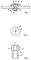
- the heavy sludge sorter has a sludge container 1 with a Bottom 31 and an adjoining cylindrical side wall 32 on.
- the sludge container 1 On the bottom side, the sludge container 1 has a diffuser base plate 2, which are at a predetermined distance extends from the bottom 31 of the slurry container and extends parallel to it and is enclosed by the side wall.
- the diffuser base plate 2 has a plurality of recess bores, in which interchangeable individual nozzles 4 are arranged.
- a pressurized water chamber 3 Under the diffuser base plate 2 is a pressurized water chamber 3 arranged.
- the pressure water chamber 3 is limited by the Base plate 31, the diffuser base plate opposite this 2 and the cylindrical side wall 32. It is a self extending through the base plate 31 into the pressure chamber 3 opening upstream water supply line 6 is provided.
- the heavy sludge sorter also has an outlet device 5 to drain the descent.
- This outlet device will formed by an outlet pipe that extends through the floor of the sludge tank 1 via the pressurized water chamber 3 into the interior of the sludge container 1 extends and the inside of the Turbidity tank 1 a valve controllable via a valve rod 8 having.
- the valve rod 8 extends through the slurry container 1 up to its top side 9.
- the slurry container also has a material feed device on the ceiling side 14, as well as a light goods drain 10. Furthermore are on the side walls displacement claws 15 for mounting of the slurry container arranged.
- the single nozzle 4 is in a bore 30 of the diffuser base plate 2 arranged.
- the nozzle body 18 has a first here cylindrical portion 33 and an adjoining second section 34.
- the first section is cylindrical educated. Its outside diameter depends on the inside diameter the hole chosen so that the first section sits in the diffuser base plate 2 with a snug fit.
- the adjacent one second section is facing away from the first section End divergent as a truncated cone.
- the nozzle section 18 engages with its first section 33 the diffuser base plate 2 and points to one of the diffuser base plate protruding section a thread.
- the nozzle is via a nut 20 and one between the diffuser baseplate 2 and the nut 20 arranged sealing washer 21 locked in the diffuser base plate.
- the reference number 19 denotes a sealing or adhesive surface.
- the nozzle body runs essentially coaxially to the bore a nozzle channel 17 on the inside of the slurry tank facing side, i.e. a narrowing on the exit side, i.e. has a nozzle neck.
- the second section is covered with a cap 16.
- This Cap 16 is made of elastic material and sits under Tension on the second section and has the task of Check valve.
- the cap 16 has a center in the cap 16 and above the outlet opening of the nozzle channel 17 arranged a crossed slot 22 that many times larger than the diameter of the outlet opening of the Nozzle channel 17 is.
- This slot acts as a check valve and blocks the passage of liquid through the nozzle 4 from Turbidity tank 1 in the pressurized water chamber 3. When passing through of liquid from the pressurized water chamber 3 into the turbidity tank 1 opens the check valve.
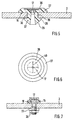
- Fig. 4 shows a further embodiment of the nozzle body 18.
- the nozzle body is made Plastic formed, but can be just like the one above Design made of steel or other materials his.
- the first section engaging in the diffuser floor 2 25 is designed as an expansion body. By bringing in of the nozzle body in the diffuser base plate 2 to Stop surface 24, the first section 25 is biased and locked in the hole by the expansion effect.
- a second section 35 provided on the analog as in the previous embodiment a cap forming the check valve is attached is.
- the embodiment of the nozzle shown in FIG. 5 differs from the previously shown embodiments in that the check valve is not in the form of a cap to be fitted is formed. Instead, the second section 37 the exit side one coaxial to the nozzle channel arranged recess in which a plate 38 made of elastic Material is glued in, which is coaxial to the central axis of the nozzle channel has a cross-shaped slot 40, which is best seen in Fig. 6.
- the nozzle body 27 differs from that previous in that the first section at its the second section facing end 29 in the manner of a dowel is slotted so that it is elastically compressible. Furthermore, the outside of the first section has one Undercut 39 whose outer diameter is essentially equal to the inside diameter of the nozzle body Bore in the nozzle bottom 2, and its expansion in the axial direction of the nozzle channel equal to the thickness of the Diffuser base plate 2 is. Numeral 28 denotes one holding pawl formed by the undercut 39.
- the second section of the nozzle body is cylindrical. On this second section is the same as that previously described Embodiments put a plastic cap on the cap base on the nozzle opening is elastic Cross-slotted section.
- the nozzles are over Line 6 pressurized water, so that the water through the check valves described above passes through. However, if the water supply is blocked, go the cross-slit elastic sections in their starting position back and thus form a check valve.
Landscapes
- Nozzles (AREA)
- Separation Of Solids By Using Liquids Or Pneumatic Power (AREA)
- Fluid-Pressure Circuits (AREA)
- Sorting Of Articles (AREA)
- Fertilizers (AREA)
Description
- Fig. 1
- einen Schwertrübesortierer gemäß einer Ausführungsform der vorliegenden Erfindung,
- Fig. 2
- eine Ausgestaltung der auswechselbaren Einzeldüse für den Schwertrübesortierer nach Fig. 1,
- Fig. 3
- eine Ausgestaltung der Rückschlagvorrichtung der Einzeldüse nach Fig. 2,
- Fig. 4
- eine weitere Ausgestaltung des Düsengrundkörpers der auswechselbaren Einzeldüse für den Schwertrübesortierer nach Fig. 1,
- Fig. 5
- noch eine weitere Ausgestaltung der auswechselbaren Einzeldüse für den Schwertrübesortierer nach Fig. 1,
- Fig. 6
- eine Ausgestaltung der Rückschlagvorrichtung der Einzeldüse nach Fig. 5,
- Fig. 7
- eine weitere Ausgestaltung der Einzeldüse für den Schwertrübesortierer nach Fig. 1.
Claims (8)
- Schwertrübesortierer miteinem Behälter (1), der einen Boden (31) und daran seitlich angrenzende Seitenwände (32) und eine in einem Abstand von dem Boden (31) angeordnete Diffusorgrundplatte (2) mit einer Mehrzahl von Düsen (4) aufweist,einer Zufuhrleitung (6), die die dem Boden (31) zugewandte Seite der Diffusorgrundplatte (2) mit Wasser unter Druck beaufschlagt, undeiner Auslaßleitung (5),
wobei die Diffusorgrundplatte (2) eine Mehrzahl von Bohrungen (30) mit darin angeordneten einzelnen Düsen mit einem Düsenkanal (17) aufweist und die Düsen (4) jeweils mit einem in Richtung der Zufuhrleitung (6) sperrenden Rückschlagventil (16, 22; 38, 40) vorgesehen sind, das aus einem geschlitzten elastischen Material besteht,
dadurch gekennzeichnet,
daß das elastische Material mittig über der Ausgangsseite des Düsenkanals (17) einen gekreuzten Schlitz (22, 40) aufweist und die Düsen (4) das Rückschlagventil (16, 22; 38, 40) jeweils als Bestandteil aufweisen. - Schwertrübesortierer nach Anspruch 1, dadurch gekennzeichnet,
daß das Rückschlagventil (16, 22; 38, 40) durch eine ausgangsseitig auf der Öffnung des Düsenkanals (17) angebrachte und den gekreuzten Schlitz aufweisende Folie ausgebildet ist. - Schwertrübesortierer nach Anspruch 1 oder 2,
dadurch gekennzeichnet,
daß jede der Düsen (4) einen Düsengrundkörper (18) aufweist, auf den als Rückschlagventil eine Kappe (16) aus dem elastischen Material aufgesetzt ist, die den gekreuzten Schlitz (22) aufweist. - Schwertrübesortierer nach Anspruch 1 oder 2,
dadurch gekennzeichnet,
daß jede der Düsen (4) einen Düsengrundkörper (18, 27) aufweist, an dem über der Ausgangsseite des Düsenkanals (17) eine Platte (38) aus dem elastischen Material befestigt ist, die den gekreuzten Schlitz (40) aufweist. - Schwertrübesortierer nach einem der Ansprüche 1 bis 4, dadurch gekennzeichnet,
daß jede der Düsen auswechselbar in der Diffusorgrundplatte (2) befestigt ist. - Schwertrübesortierer nach einem der Ansprüche 1 bis 5, dadurch gekennzeichnet,
daß die Düse (4) den Düsenkanal (17) im wesentlichen koaxial zu der Bohrung (30) verlaufend, einen ersten Abschnitt (25, 33, 39) zum Ineingriffbringen mit der Diffusorgrundplatte (2) und einen daran angrenzenden zweiten Abschnitt (34, 35, 27) zum Aufnehmen des Rückschlagventils aufweist. - Schwertrübesortierer nach Anspruch 6, dadurch gekennzeichnet,
daß der erste Abschnitt (25, 33, 39) auf seiner dem zweiten Abschnitt abgewandten Seite so ausgebildet ist, daß eine Arretierung in der Diffusorgrundplatte (2) erfolgt. - Schwertrübesortierer nach Anspruch 6 oder 7, dadurch gekennzeichnet,
daß auf dem zweiten Abschnitt (34, 35, 27) auf der dem ersten Abschnitt abgewandten Seite eine an der Stelle der Austrittsöffnung des Düsenkanals (17) den gekreuzten Schlitz aufweisende Kappe (16) aufgesetzt ist.
Applications Claiming Priority (3)
| Application Number | Priority Date | Filing Date | Title |
|---|---|---|---|
| DE19536303A DE19536303A1 (de) | 1995-09-29 | 1995-09-29 | Schwertrübesortierer |
| DE19536303 | 1995-09-29 | ||
| PCT/EP1996/004011 WO1997012682A1 (de) | 1995-09-29 | 1996-09-12 | Schwertrübesortierer |
Publications (3)
| Publication Number | Publication Date |
|---|---|
| EP0799092A1 EP0799092A1 (de) | 1997-10-08 |
| EP0799092B1 true EP0799092B1 (de) | 1999-08-25 |
| EP0799092B2 EP0799092B2 (de) | 2004-06-16 |
Family
ID=7773566
Family Applications (1)
| Application Number | Title | Priority Date | Filing Date |
|---|---|---|---|
| EP96932513A Expired - Lifetime EP0799092B2 (de) | 1995-09-29 | 1996-09-12 | Schwertrübesortierer |
Country Status (5)
| Country | Link |
|---|---|
| EP (1) | EP0799092B2 (de) |
| AT (1) | ATE183671T1 (de) |
| DE (2) | DE19536303A1 (de) |
| DK (1) | DK0799092T4 (de) |
| WO (1) | WO1997012682A1 (de) |
Families Citing this family (2)
| Publication number | Priority date | Publication date | Assignee | Title |
|---|---|---|---|---|
| US9833790B2 (en) * | 2015-07-09 | 2017-12-05 | Jesse W. Rhodes, JR. | Assembly and method for gravitationally separating gold from small particles |
| EP4182094A4 (de) * | 2020-07-16 | 2025-05-07 | Kale, Tebogo | Klassifikator und verfahren zum klassifizieren |
Family Cites Families (8)
| Publication number | Priority date | Publication date | Assignee | Title |
|---|---|---|---|---|
| US2105126A (en) * | 1936-04-01 | 1938-01-11 | New Jersey Zinc Co | Classification |
| US3485365A (en) * | 1968-01-11 | 1969-12-23 | Dorr Oliver Inc | Hydraulic upflow classification apparatus |
| GB1298027A (en) * | 1970-06-11 | 1972-11-29 | Wilkinson Rubber Linatex Ltd | Improvements in or relating to classifiers |
| FR2418676A1 (fr) * | 1978-03-03 | 1979-09-28 | Irrifrance | Arroseur statique pour systemes d'arrosage |
| DE3013668C2 (de) † | 1980-04-09 | 1982-11-18 | Schauenburg Maschinen- und Anlagen-Bau GmbH, 4330 Mülheim | Vorrichtung für die Naßaufbereitung und Entwässerung von Sand |
| US4539103A (en) * | 1982-04-15 | 1985-09-03 | C-H Development And Sales, Inc. | Hydraulic separating method and apparatus |
| US4807761A (en) * | 1983-09-22 | 1989-02-28 | C-H Development & Sales, Inc. | Hydraulic separating method and apparatus |
| DE4118020A1 (de) * | 1991-06-01 | 1992-12-03 | Schauenburg Masch | Verfahren zum abscheiden spezifisch leichter bestandteile aus einer truebe durch aufstromsortierung und messvorrichtung dazu |
-
1995
- 1995-09-29 DE DE19536303A patent/DE19536303A1/de not_active Ceased
-
1996
- 1996-09-12 EP EP96932513A patent/EP0799092B2/de not_active Expired - Lifetime
- 1996-09-12 WO PCT/EP1996/004011 patent/WO1997012682A1/de not_active Ceased
- 1996-09-12 DE DE59602867T patent/DE59602867D1/de not_active Expired - Fee Related
- 1996-09-12 AT AT96932513T patent/ATE183671T1/de not_active IP Right Cessation
- 1996-09-12 DK DK96932513T patent/DK0799092T4/da active
Also Published As
| Publication number | Publication date |
|---|---|
| DK0799092T3 (da) | 1999-12-13 |
| EP0799092A1 (de) | 1997-10-08 |
| ATE183671T1 (de) | 1999-09-15 |
| DE19536303A1 (de) | 1997-04-03 |
| DE59602867D1 (de) | 1999-09-30 |
| DK0799092T4 (da) | 2004-07-19 |
| EP0799092B2 (de) | 2004-06-16 |
| WO1997012682A1 (de) | 1997-04-10 |
Similar Documents
| Publication | Publication Date | Title |
|---|---|---|
| DE69114956T2 (de) | Düsenkappe für einen Klebstoffspender. | |
| DE3514287A1 (de) | Druckluft-betriebene spruehduese | |
| EP1644654A1 (de) | Einschraubbares rückschlagventil | |
| DE3203762A1 (de) | Rueckstroemsperre | |
| EP2084451A2 (de) | Schmiermittelverteiler | |
| DE19841928C2 (de) | Vorrichtung zur Beseitigung von Verunreinigungen an Schnellspanneinheiten | |
| DE2323846A1 (de) | Spritz- bzw. spruehduese | |
| EP0724486A1 (de) | Sprühblock eines sprühwerkzeugs | |
| EP0229387B1 (de) | Vorrichtung zum Belüften von Wasser | |
| EP0799092B1 (de) | Schwertrübesortierer | |
| DE3925293C3 (de) | Vorrichtung zum lösbaren Verbinden einer Druckmittelleitung an einem Druckmittelanschluß | |
| DE2453670A1 (de) | Einrichtung zum verteilen von gasen in fluessigkeiten | |
| DE60304293T2 (de) | Sprühfeuchtwerk | |
| DE3807626A1 (de) | Befestigungsvorrichtung | |
| DE19630477A1 (de) | Offenend-Spinnvorrichtung | |
| DE202017005877U1 (de) | Düse zum Einbau in eine Reinigungsdüse | |
| DE4214779A1 (de) | Handfarbwechsler | |
| DE8203649U1 (de) | Düsenhalter für landwirtschaftliche Spritzgeräte, insbesondere Feldspritzen | |
| DE102019102882A1 (de) | Halterung für ein Kraftfahrzeugkennzeichen | |
| EP0332157B1 (de) | Anordnung zur Verbindung einer Verteilvorrichtung mit einer Fluidzuleitung | |
| DE378501C (de) | Vorrichtung zum Duengen unter gleichzeitiger Bewaesserung | |
| DE9410772U1 (de) | Vorrichtung zur dichten Befestigung einer Unterkonstruktion an einer Wand o.dgl. | |
| DE3416625C2 (de) | Oberbecher-Spritzpistole | |
| DE20019722U1 (de) | Befestigungsvorrichtung | |
| DE3804878A1 (de) | Maschine zum aetzen von gegenstaenden |
Legal Events
| Date | Code | Title | Description |
|---|---|---|---|
| PUAI | Public reference made under article 153(3) epc to a published international application that has entered the european phase |
Free format text: ORIGINAL CODE: 0009012 |
|
| 17P | Request for examination filed |
Effective date: 19970414 |
|
| AK | Designated contracting states |
Kind code of ref document: A1 Designated state(s): AT BE CH DE DK FR GB LI NL |
|
| 17Q | First examination report despatched |
Effective date: 19971113 |
|
| GRAG | Despatch of communication of intention to grant |
Free format text: ORIGINAL CODE: EPIDOS AGRA |
|
| GRAG | Despatch of communication of intention to grant |
Free format text: ORIGINAL CODE: EPIDOS AGRA |
|
| GRAH | Despatch of communication of intention to grant a patent |
Free format text: ORIGINAL CODE: EPIDOS IGRA |
|
| GRAH | Despatch of communication of intention to grant a patent |
Free format text: ORIGINAL CODE: EPIDOS IGRA |
|
| GRAA | (expected) grant |
Free format text: ORIGINAL CODE: 0009210 |
|
| AK | Designated contracting states |
Kind code of ref document: B1 Designated state(s): AT BE CH DE DK FR GB LI NL |
|
| REF | Corresponds to: |
Ref document number: 183671 Country of ref document: AT Date of ref document: 19990915 Kind code of ref document: T |
|
| REG | Reference to a national code |
Ref country code: CH Ref legal event code: NV Representative=s name: R. A. EGLI & CO. PATENTANWAELTE Ref country code: CH Ref legal event code: EP |
|
| GBT | Gb: translation of ep patent filed (gb section 77(6)(a)/1977) |
Effective date: 19990827 |
|
| REF | Corresponds to: |
Ref document number: 59602867 Country of ref document: DE Date of ref document: 19990930 |
|
| ET | Fr: translation filed | ||
| REG | Reference to a national code |
Ref country code: DK Ref legal event code: T3 |
|
| PLAV | Examination of admissibility of opposition |
Free format text: ORIGINAL CODE: EPIDOS OPEX |
|
| PLBI | Opposition filed |
Free format text: ORIGINAL CODE: 0009260 |
|
| PLAV | Examination of admissibility of opposition |
Free format text: ORIGINAL CODE: EPIDOS OPEX |
|
| PLBF | Reply of patent proprietor to notice(s) of opposition |
Free format text: ORIGINAL CODE: EPIDOS OBSO |
|
| 26 | Opposition filed |
Opponent name: SCHAUENBURG MASCHINEN- UND ANLAGEN-BAU GMBH Effective date: 20000518 |
|
| NLR1 | Nl: opposition has been filed with the epo |
Opponent name: SCHAUENBURG MASCHINEN- UND ANLAGEN-BAU GMBH |
|
| PLBF | Reply of patent proprietor to notice(s) of opposition |
Free format text: ORIGINAL CODE: EPIDOS OBSO |
|
| PLBF | Reply of patent proprietor to notice(s) of opposition |
Free format text: ORIGINAL CODE: EPIDOS OBSO |
|
| PLAW | Interlocutory decision in opposition |
Free format text: ORIGINAL CODE: EPIDOS IDOP |
|
| REG | Reference to a national code |
Ref country code: GB Ref legal event code: IF02 |
|
| APAC | Appeal dossier modified |
Free format text: ORIGINAL CODE: EPIDOS NOAPO |
|
| APAC | Appeal dossier modified |
Free format text: ORIGINAL CODE: EPIDOS NOAPO |
|
| APAE | Appeal reference modified |
Free format text: ORIGINAL CODE: EPIDOS REFNO |
|
| APBU | Appeal procedure closed |
Free format text: ORIGINAL CODE: EPIDOSNNOA9O |
|
| PUAH | Patent maintained in amended form |
Free format text: ORIGINAL CODE: 0009272 |
|
| STAA | Information on the status of an ep patent application or granted ep patent |
Free format text: STATUS: PATENT MAINTAINED AS AMENDED |
|
| 27A | Patent maintained in amended form |
Effective date: 20040616 |
|
| AK | Designated contracting states |
Kind code of ref document: B2 Designated state(s): AT BE CH DE DK FR GB LI NL |
|
| GBTA | Gb: translation of amended ep patent filed (gb section 77(6)(b)/1977) | ||
| REG | Reference to a national code |
Ref country code: CH Ref legal event code: AEN Free format text: AUFRECHTERHALTUNG DES PATENTES IN GEAENDERTER FORM |
|
| REG | Reference to a national code |
Ref country code: DK Ref legal event code: T4 |
|
| NLR2 | Nl: decision of opposition |
Effective date: 20040616 |
|
| NLR3 | Nl: receipt of modified translations in the netherlands language after an opposition procedure | ||
| ET3 | Fr: translation filed ** decision concerning opposition | ||
| PGFP | Annual fee paid to national office [announced via postgrant information from national office to epo] |
Ref country code: GB Payment date: 20050831 Year of fee payment: 10 |
|
| PGFP | Annual fee paid to national office [announced via postgrant information from national office to epo] |
Ref country code: NL Payment date: 20050919 Year of fee payment: 10 |
|
| PGFP | Annual fee paid to national office [announced via postgrant information from national office to epo] |
Ref country code: FR Payment date: 20050920 Year of fee payment: 10 |
|
| PGFP | Annual fee paid to national office [announced via postgrant information from national office to epo] |
Ref country code: BE Payment date: 20050922 Year of fee payment: 10 Ref country code: AT Payment date: 20050922 Year of fee payment: 10 |
|
| PGFP | Annual fee paid to national office [announced via postgrant information from national office to epo] |
Ref country code: CH Payment date: 20050923 Year of fee payment: 10 |
|
| PGFP | Annual fee paid to national office [announced via postgrant information from national office to epo] |
Ref country code: DK Payment date: 20050926 Year of fee payment: 10 |
|
| PGFP | Annual fee paid to national office [announced via postgrant information from national office to epo] |
Ref country code: DE Payment date: 20050930 Year of fee payment: 10 |
|
| APAH | Appeal reference modified |
Free format text: ORIGINAL CODE: EPIDOSCREFNO |
|
| PG25 | Lapsed in a contracting state [announced via postgrant information from national office to epo] |
Ref country code: AT Free format text: LAPSE BECAUSE OF NON-PAYMENT OF DUE FEES Effective date: 20060912 |
|
| PG25 | Lapsed in a contracting state [announced via postgrant information from national office to epo] |
Ref country code: LI Free format text: LAPSE BECAUSE OF NON-PAYMENT OF DUE FEES Effective date: 20060930 Ref country code: CH Free format text: LAPSE BECAUSE OF NON-PAYMENT OF DUE FEES Effective date: 20060930 Ref country code: BE Free format text: LAPSE BECAUSE OF NON-PAYMENT OF DUE FEES Effective date: 20060930 |
|
| PG25 | Lapsed in a contracting state [announced via postgrant information from national office to epo] |
Ref country code: DK Free format text: LAPSE BECAUSE OF NON-PAYMENT OF DUE FEES Effective date: 20061002 |
|
| PG25 | Lapsed in a contracting state [announced via postgrant information from national office to epo] |
Ref country code: NL Free format text: LAPSE BECAUSE OF NON-PAYMENT OF DUE FEES Effective date: 20070401 |
|
| PG25 | Lapsed in a contracting state [announced via postgrant information from national office to epo] |
Ref country code: DE Free format text: LAPSE BECAUSE OF NON-PAYMENT OF DUE FEES Effective date: 20070403 |
|
| REG | Reference to a national code |
Ref country code: DK Ref legal event code: EBP |
|
| REG | Reference to a national code |
Ref country code: CH Ref legal event code: PL |
|
| GBPC | Gb: european patent ceased through non-payment of renewal fee |
Effective date: 20060912 |
|
| NLV4 | Nl: lapsed or anulled due to non-payment of the annual fee |
Effective date: 20070401 |
|
| REG | Reference to a national code |
Ref country code: FR Ref legal event code: ST Effective date: 20070531 |
|
| PG25 | Lapsed in a contracting state [announced via postgrant information from national office to epo] |
Ref country code: GB Free format text: LAPSE BECAUSE OF NON-PAYMENT OF DUE FEES Effective date: 20060912 |
|
| BERE | Be: lapsed |
Owner name: *BRAUER AUFBEREITUNGSMASCHINEN G.M.B.H. & CO. FORD Effective date: 20060930 |
|
| PG25 | Lapsed in a contracting state [announced via postgrant information from national office to epo] |
Ref country code: FR Free format text: LAPSE BECAUSE OF NON-PAYMENT OF DUE FEES Effective date: 20061002 |