EP0799092B2 - Dense medium classifier - Google Patents
Dense medium classifier Download PDFInfo
- Publication number
- EP0799092B2 EP0799092B2 EP96932513A EP96932513A EP0799092B2 EP 0799092 B2 EP0799092 B2 EP 0799092B2 EP 96932513 A EP96932513 A EP 96932513A EP 96932513 A EP96932513 A EP 96932513A EP 0799092 B2 EP0799092 B2 EP 0799092B2
- Authority
- EP
- European Patent Office
- Prior art keywords
- nozzle
- dense
- diffuser
- baseplate
- nozzles
- Prior art date
- Legal status (The legal status is an assumption and is not a legal conclusion. Google has not performed a legal analysis and makes no representation as to the accuracy of the status listed.)
- Expired - Lifetime
Links
- XLYOFNOQVPJJNP-UHFFFAOYSA-N water Substances O XLYOFNOQVPJJNP-UHFFFAOYSA-N 0.000 claims description 12
- 239000013013 elastic material Substances 0.000 claims description 6
- 238000004519 manufacturing process Methods 0.000 abstract description 5
- 239000010802 sludge Substances 0.000 description 22
- 229910000831 Steel Inorganic materials 0.000 description 5
- 239000002002 slurry Substances 0.000 description 5
- 239000010959 steel Substances 0.000 description 5
- 239000000463 material Substances 0.000 description 4
- 238000011144 upstream manufacturing Methods 0.000 description 4
- 239000007788 liquid Substances 0.000 description 2
- 239000004033 plastic Substances 0.000 description 2
- 238000007789 sealing Methods 0.000 description 2
- 239000000853 adhesive Substances 0.000 description 1
- 230000001070 adhesive effect Effects 0.000 description 1
- 210000000078 claw Anatomy 0.000 description 1
- 230000007547 defect Effects 0.000 description 1
- 230000001419 dependent effect Effects 0.000 description 1
- 238000006073 displacement reaction Methods 0.000 description 1
- 230000000694 effects Effects 0.000 description 1
- 239000011888 foil Substances 0.000 description 1
- 239000007787 solid Substances 0.000 description 1
- 230000006641 stabilisation Effects 0.000 description 1
- 238000011105 stabilization Methods 0.000 description 1
Images

Classifications
-
- B—PERFORMING OPERATIONS; TRANSPORTING
- B03—SEPARATION OF SOLID MATERIALS USING LIQUIDS OR USING PNEUMATIC TABLES OR JIGS; MAGNETIC OR ELECTROSTATIC SEPARATION OF SOLID MATERIALS FROM SOLID MATERIALS OR FLUIDS; SEPARATION BY HIGH-VOLTAGE ELECTRIC FIELDS
- B03B—SEPARATING SOLID MATERIALS USING LIQUIDS OR USING PNEUMATIC TABLES OR JIGS
- B03B5/00—Washing granular, powdered or lumpy materials; Wet separating
- B03B5/62—Washing granular, powdered or lumpy materials; Wet separating by hydraulic classifiers, e.g. of launder, tank, spiral or helical chute concentrator type
- B03B5/623—Upward current classifiers
Definitions
- the present invention relates to a heavy sludge sorter according to the generic term of Claim 1.
- Such a sludge sorter except that the diffuser base plate has a plurality of Bores with individual nozzles arranged in them having a nozzle channel and the nozzles each provided with the appropriate check valve are known from DE 36 39 044 C1.
- a conventional heavy pulp sorter becomes a homogeneous one Upflow through a rubber plate provided with nozzles generated, which is used for mechanical stabilization located between two steel sheets, both Steel sheet corresponding recess holes exhibit.
- the use of such a rubber sheet has the disadvantage that this is due to mechanical Tolerances of these Holding devices, e.g. the steel sheets, deformed or is not held stable. This puts the pressure on the entrance side of the rubber plate is no longer even distributed and the uniformity of the upstream disturbed.
- Such a rubber sheet is also very susceptible against mechanical stress and in the event of a mechanical defect must cover the entire rubber sheet to be replaced. Furthermore, the manufacturing such rubber sheets expensive because the mechanical Bracket, i.e. both steel sheets between which themselves the rubber plate is located, with recess holes must be provided.
- One with a diffuser base plate with single nozzles provided heavy sludge sorter has the advantages that the individual nozzles are independent of the manufacturing tolerances always with the diffuser base plate even pressure are applied so that a constant upflow is always guaranteed.
- By making a diffuser base plate with Individual nozzles simplify the manufacture of the diffuser base plate, since only one plate is used and only this must be drilled.
- There a diffuser base plate, for example 1500 holes has a significant reduction of the manufacturing effort.
- By training the check valve prevents the ingress of sinking material into the pressurized water chamber if the upstream water supply fails prevented.
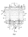
- the heavy sludge sorter has a slurry tank 1 with a bottom 31 and an adjoining cylindrical side wall 32 on.
- the sludge container 1 On the bottom side, the sludge container 1 a diffuser base plate 2, which is in a predetermined Distance from the bottom 31 of the sludge container and extends parallel to it and from the side wall is enclosed.
- the diffuser base plate 2 has a variety of recess holes in which interchangeable individual nozzles 4 are arranged.
- the pressurized water chamber 3 is delimited by the base plate 31, which this opposite diffuser base plate 2 and the cylindrical side wall 32. It is characterized by the Base plate 31 extending into the pressure chamber 3 opening upstream water supply line 6 is provided.
- the heavy sludge sorter has a Discharge device 5 for draining the sinking material.
- This outlet device is through an outlet line formed by the bottom of the slurry container 1 via the pressurized water chamber 3 into the interior of the sludge tank 1 extends and the inside of the sludge tank 1 a valve controllable via a valve rod 8 having.
- the valve rod 8 extends through the sludge container 1 up to its top side 9.
- the slurry container also has a ceiling a material feed device 14 and one Light goods drain 10. Furthermore are on the side walls Displacement claws 15 for holding the slurry container arranged.
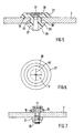
- the individual nozzles 4 of the diffuser base plate 2 is in a bore 30 the diffuser base plate 2 arranged.
- the nozzle body 18 here has a first cylindrical Section 33 and a subsequent second Section 34 on.
- the first section is cylindrical. Its outside diameter is dependent selected from the inside diameter of the bore so that the first section with a snug fit in the diffuser baseplate 2 sits.
- the adjacent second section is closed its end facing away from the first section divergent as a truncated cone.
- the nozzle body 18 engages with its first section 33 in the diffuser base plate 2 and shows on one protruding portion of the diffuser base plate Thread on.
- the nozzle is over a nut 20 and one between the diffuser base plate 2 and the nut 20 arranged sealing disc 21 in the diffuser base plate locked.
- Reference numeral 19 denotes one Sealing or adhesive surface.
- nozzle channel 17 which on the the side facing the inside of the sludge container, i.e. a narrowing on the outlet side, i.e. one Has nozzle neck.
- the second section has a cap 16 overdrawn.
- This cap 16 is made of elastic material formed and sitting under tension on the second Section and has the function of the check valve.
- the cap 16 is centered in the Cap 16 and over the outlet opening of the nozzle channel 17 arranged a crossed slot 22 which many times larger than the diameter of the outlet opening of the nozzle channel 17. That slit acts as a check valve and blocks the passage of liquid through the nozzle 4 from the sludge tank 1 in the Pressurized water chamber 3.
- liquid passes from the pressurized water chamber 3 into the turbidity tank 1 opens the check valve.
- Fig. 4 shows a further embodiment of the Nozzle base body 18.
- the Nozzle base body made of plastic, but can just like in the above design made of steel or other materials.
- the one in the diffuser floor 2 engaging first section 25 is as Spreading body formed.
- the first section 25 is biased and by the expansion effect in the bore locked.
- a second section 35 is provided to which analogous to the previous embodiment a cap forming the check valve is attached is.
- FIG Nozzle differs from the previously shown embodiments in that the check valve is not formed in the form of a cap to be put on. Instead, the second section 37 faces on the outlet side Side one coaxial with the nozzle channel arranged recess into which a plate 38 elastic material is glued, which is coaxial to the Center axis of the nozzle channel a cross-shaped Has slot 40, which is best seen in FIG. 6 is.
- the nozzle body differs 27 of the previous ones in that the first section on its side facing away from the second section End 29 is slotted like a dowel, so that it is elastically compressible. Further points the outside of the first section an undercut 39 on whose outer diameter in substantially equal to the inside diameter of the Nozzle body receiving bore in the nozzle bottom 2, and its expansion in the axial direction of the nozzle channel is equal to the thickness of the diffuser base plate 2 is. Numeral 28 denotes a by the undercut 39 formed pawl.
- the second section of the nozzle body is cylindrical educated. On this second section is like in the previously described embodiments Plastic cap attached to her on the Cap opening the elastic opening Cross-slotted section.
- the nozzles via line 6 with pressurized Water is applied so that the water passes through passes through the check valves described above. However, if the water supply is blocked, they go Elastic sections divided into a cross slot shape their starting position back and thus form a check valve.
Landscapes
- Nozzles (AREA)
- Fluid-Pressure Circuits (AREA)
- Separation Of Solids By Using Liquids Or Pneumatic Power (AREA)
- Sorting Of Articles (AREA)
- Fertilizers (AREA)
Abstract
Description
Die vorliegende Erfindung bezieht sich auf einen Schwertrübesortierer nach dem Oberbegriff des Anspruches 1.The present invention relates to a heavy sludge sorter according to the generic term of Claim 1.
Ein solcher Schwertrübesortierer, ausgenommen, daß die Diffusorgrundplatte eine Mehrzahl von Bohrungen mit darin angeordneten einzelnen Düsen mit einem Düsenkanal aufweist und die Düsen jeweils mit dem entsprechenden Rückschlagventil vorgesehen sind, ist aus der DE 36 39 044 C1 bekannt. Bei einem herkömmlichen Schwertrübesortierer wird ein homogener Aufstrom durch eine mit Düsen versehene Gummiplatte erzeugt, die sich zur mechanischen Stabilisierung zwischen zwei Stahlblechen befindet, wobei beide Stahlbleche entsprechende Ausnehmungsbohrungen aufweisen. Die Verwendung von einer solchen Gummiplatte hat den Nachteil, daß sich diese aufgrund mechanischer Toleranzen der diesen haltenden Halteeinrichtungen, wie z.B. die Stahlbleche, verformt bzw. nicht stabil gehaltert ist. Dadurch ist der Druck an der Eingangsseite der Gummiplatte nicht mehr gleichmäßig verteilt und die Gleichmäßigkeit des Aufstroms gestört. Ferner ist eine solche Gummiplatte sehr anfällig gegen mechanische Belastung und im Falle eines mechanischen Defekts muß die gesamte Gummiplatte ausgewechselt werden. Desweiteren ist die Fertigung solcher Gummiplatten aufwendig, da die mechanische Halterung, d.h. beide Stahlbleche zwischen denen sich die Gummiplatte befindet, mit Ausnehmungsbohrungen versehen werden müssen.Such a sludge sorter, except that the diffuser base plate has a plurality of Bores with individual nozzles arranged in them having a nozzle channel and the nozzles each provided with the appropriate check valve are known from DE 36 39 044 C1. At a conventional heavy pulp sorter becomes a homogeneous one Upflow through a rubber plate provided with nozzles generated, which is used for mechanical stabilization located between two steel sheets, both Steel sheet corresponding recess holes exhibit. The use of such a rubber sheet has the disadvantage that this is due to mechanical Tolerances of these Holding devices, e.g. the steel sheets, deformed or is not held stable. This puts the pressure on the entrance side of the rubber plate is no longer even distributed and the uniformity of the upstream disturbed. Such a rubber sheet is also very susceptible against mechanical stress and in the event of a mechanical defect must cover the entire rubber sheet to be replaced. Furthermore, the manufacturing such rubber sheets expensive because the mechanical Bracket, i.e. both steel sheets between which themselves the rubber plate is located, with recess holes must be provided.
Aus der US 4 539 106, ausgenommen, daß die Düsen jeweils mit dem entsprechenden Rückschlagventil vorgesehen sind und aus der US 2 105 126 ist jeweils ein Schwertrübesortierer nach dem Oberbegriff des Anspruches 1 bekannt, wobei bei der US 2 105126 auf einer Düse eine als Rückschlagventil wirkende Gummikappe mit einem Schlitz aufgesetzt und befestigt wird.From US 4,539,106, except that the Nozzles each with the corresponding check valve are provided and from US 2 105 126 a heavy sludge sorter according to the generic term of claim 1 known, wherein in US 2 105126th on a nozzle acting as a check valve Rubber cap with a slit put on and fastened becomes.
Aus der GB 1 298 027 B ist ein Schwertrübesortierer bekannt, bei dem Düsen durch einen gekreuzten Schlitz in einer Folie, gegen das Eindringen gröberer Feststoffe geschützt sind.From GB 1 298 027 B is a heavy sludge sorter known, where the nozzle through a crossed Slit in a foil, against the ingress of coarser solids are protected.
Es ist daher die Aufgabe der vorliegenden Erfindung einen Schwertrübesortierer anzugeben, bei dem ein homogener Aufstrom in vorteilhafter Weise erreicht werden kann, der wartungsfreundlicher betrieben und in wirtschaftlicherer Weise hergestellt werden kann.It is therefore the task of the present Invention to provide a heavy sludge sorter at which a homogeneous upstream in an advantageous manner can be achieved, which is more maintenance-friendly and be manufactured in a more economical manner can.
Diese Aufgabe wird durch einen Schwertrübesortierer nach Anspruch 1 gelöst. Weiterbildungen der Erfindung sind in den Unteransprüchen angegeben.This task is carried out by a heavy sludge sorter solved according to claim 1. Further training of the Invention are specified in the subclaims.
Ein mit einer Diffusorgrundplatte mit Einseldüsen versehener Schwertrübesortierer weist die Vorteile auf, daß die Einzeldüsen unabhängig von den Fertigungstoleranzen der Diffusorgrundplatte immer mit gleichmäßigem Druck beaufschlagt werden, so daß immer ein gleichmäßiger Aufstrom gewährleistet ist. Durch die Ausfertigung einer Diffusorgrundplatte mit Einzeldüsen vereinfacht sich die Herstellung der Diffusorgrundplatte, da nur eine Platte verwendet wird und nur diese mit Bohrungen versehen werden muß. Da eine Diffusorgrundplatte beispielsweise 1500 Bohrungen aufweist, stellt dies eine beträchtliche Reduktion des Herstellungsaufwands dar. Durch die Ausbildung des Rückschlagventils wird das Eindringen von Sinkgut in die Druckwasserkammer bei Ausfall der Aufstromwasserzuführung verhindert.One with a diffuser base plate with single nozzles provided heavy sludge sorter has the advantages that the individual nozzles are independent of the manufacturing tolerances always with the diffuser base plate even pressure are applied so that a constant upflow is always guaranteed. By making a diffuser base plate with Individual nozzles simplify the manufacture of the diffuser base plate, since only one plate is used and only this must be drilled. There a diffuser base plate, for example 1500 holes has a significant reduction of the manufacturing effort. By training the check valve prevents the ingress of sinking material into the pressurized water chamber if the upstream water supply fails prevented.
Weitere Merkmale und Zweckmäßigkeiten der Erfindung ergeben sich aus der folgenden Beschreibung von Ausführungsbeispielen anhand der Figuren. Von den Figuren zeigen:
- Fig. 1
- einen Schwertrübesortierer gemäß einer Ausführungsform der vorliegenden Erfindung,
- Fig. 2
- eine Ausgestaltung der auswechselbaren Einzeldüse für den Schwertrübesortierer nach Fig. 1,
- Fig. 3
- eine Ausgestaltung der Rückschlagvorrichtung der Einzeldüse nach Fig. 2,
- Fig. 4
- eine weitere Ausgestaltung des Düsengrundkörpers der auswechselbaren Einzeldüse für den Schwertrübesortierer nach Fig. 1,
- Fig. 5
- noch eine weitere Ausgestaltung der auswechselbaren Einzeldüse für den Schwertrübesortierer nach Fig. 1,
- Fig. 6
- eine Ausgestaltung der Rückschlagvorrichtung der Einzeldüse nach Fig. 5,
- Fig. 7
- eine weitere Ausgestaltung der Einzeldüse für den Schwertrübesortierer nach Fig. 1.
- Fig. 1
- a slurry sorter according to an embodiment of the present invention,
- Fig. 2
- 1 shows an embodiment of the exchangeable individual nozzle for the heavy sludge sorter according to FIG. 1,
- Fig. 3
- an embodiment of the non-return device of the individual nozzle according to FIG. 2,
- Fig. 4
- 1 shows a further embodiment of the basic nozzle body of the exchangeable individual nozzle for the heavy sludge sorter according to FIG. 1,
- Fig. 5
- yet another embodiment of the exchangeable individual nozzle for the heavy sludge sorter according to FIG. 1,
- Fig. 6
- an embodiment of the check device of the individual nozzle according to FIG. 5,
- Fig. 7
- a further embodiment of the individual nozzle for the heavy sludge sorter according to FIG. 1.
Mit Bezug auf Fig. 1 wird nun eine Ausführungsform
des Schwertrübesortierers gemäß der vorliegenden
Erfindung beschrieben. Der Schwertrübesortierer
weist einen Trübebehälter 1 mit einem Boden
31 und einer daran anschließenden zylindrischen Seitenwand
32 auf. Bodenseitig weist der Trübebehälter 1
eine Diffusorgrundplatte 2 auf, die sich in einem vorbestimmten
Abstand vom Boden 31 des Trübebehälters
und parallel zu diesem erstreckt und von der Seitenwand
umschlossen ist. Die Diffusorgrundplatte 2 weist
eine Vielzahl Ausnehmungsbohrungen auf, in denen
auswechselbare Einzeldüsen 4 angeordnet sind.With reference to Fig. 1, an embodiment will now
of the heavy sludge sorter according to the present
Invention described. The heavy sludge sorter
has a slurry tank 1 with a
Unter der Diffusorgrundplatte 2 ist eine Druckwasserkammer
3 angeordnet. Die Druckwasserkammer
3 wird begrenzt von der Bodenplatte 31, der dieser
gegenüberliegenden Diffusorgrundplatte 2 und der
zylindrischen Seitenwand 32. Es ist eine sich durch die
Bodenplatte 31 erstreckende, in die Druckkammer 3
mündende Aufstromwasserzuführleitung 6 vorgesehen.Under the
Ferner weist der Schwertrübesortierer eine
Auslaßvorrichtung 5 zum Ablassen des Sinkguts auf.
Diese Auslaßvorrichtung wird durch eine Auslaßleitung
gebildet, die sich durch den Boden des Trübebehälters
1 über die Druckwasserkammer 3 in das Innere des Trübebehälters
1 erstreckt und die im Inneren des Trübebehälters
1 ein über eine Ventilstange 8 steuerbares Ventil
aufweist. Dabei erstreckt sich die Ventilstange 8 durch
den Trübebehälter 1 bis zu dessen Deckseite 9.In addition, the heavy sludge sorter has a
Discharge device 5 for draining the sinking material.
This outlet device is through an outlet line
formed by the bottom of the slurry container
1 via the
Der Trübebehälter weist deckenseitig ferner
eine Materialaufgabevorrichtung 14 auf, sowie einen
Leichtgutablauf 10. Ferner sind an den Seitenwänden
Verlagerungspratzen 15 zur Halterung des Trübebehälters
angeordnet.The slurry container also has a ceiling
a
Mit Bezug auf Fig. 2 wird nun eine erste Ausgestaltung
der Einzeldüsen 4 der Diffusorgrundplatte 2
beschrieben. Die Einzeldüse 4 ist in einer Bohrung 30
der Diffusorgrundplatte 2 angeordnet. Der Düsengrundkörper
18 weist hier einen ersten zylindrischen
Abschnitt 33 und einen daran anschließenden zweiten
Abschnitt 34 auf. Der erste Abschnitt ist zylindrisch ausgebildet.
Sein Außendurchmesser ist in Abhängigkeit
vom Innendurchmesser der Bohrung so gewählt, daß
der erste Abschnitt mit Paßsitz in der Diffusorgrundplatte
2 sitzt. Der angrenzende zweite Abschnitt ist zu
seinem, dem ersten Abschnitt abgewandten Ende hin
divergent als Kegelstumpf ausgebildet. Der Düsengrundkörper
18 greift mit seinem ersten Abschnitt 33 in
die Diffusorgrundplatte 2 ein und weist auf einem aus
der Diffusorgrundplatte hervorstehenden Abschnitt ein
Gewinde auf. Die Düse ist über eine Mutter 20 und eine
zwischen der Diffusorgrundplatte 2 und der Mutter 20
angeordnete Dichtungsscheibe 21 in der Diffusorgrundplatte
arretiert. Das Bezugszeichen 19 bezeichnet eine
Dicht- bzw. Klebefläche.With reference to Fig. 2 is now a first embodiment
the individual nozzles 4 of the
Im Düsengrundkörper verläuft im wesentlichen
koaxial zur Bohrung ein Düsenkanal 17, der auf der
dem Inneren des Trübebehälters zugewandten Seite,
d.h. der Austrittsseite eine Verengung, d.h. einen
Düsenhals aufweist.Essentially runs in the nozzle body
coaxial to the bore, a
Der zweite Abschnitt ist mit einer Kappe 16
überzogen. Diese Kappe 16 ist aus elastischem Material
gebildet und sitzt unter Spannung auf dem zweiten
Abschnitt und hat die Aufgabe des Rückschlagventils.
Zu diesem Zweck weist die Kappe 16 mittig in der
Kappe 16 und über der Austrittsöffnung des Düsenkanals
17 angeordnet einen gekreuzten Schlitz 22 , der
um ein vielfaches größer als der Durchmesser der Austrittsöffnung
des Düsenkanals 17 ist. Dieser Schlitz
wirkt als Rückschlagventil und sperrt den Flüssigkeitsdurchtritt
durch die Düse 4 vom Trübebehälter 1 in die
Druckwasserkammer 3. Beim Durchtritt von Flüssigkeit
von der Druckwasserkammer 3 in den Trübebehälter 1
öffnet das Rückschlagventil.The second section has a
Fig. 4 zeigt eine weitere Ausgestaltung des
Düsengrundkörpers 18. In dieser Ausgestaltung ist der
Düsengrundkörper aus Kunststoff gebildet, kann aber
genau wie in der obigen Ausgestaltung aus Stahl oder
anderen Materialien gebildet sein. Der in den Diffusorboden
2 eingreifende erste Abschnitt 25 ist dabei als
Spreizkörper ausgebildet. Durch das Einbringen des
Düsenkörpers in die Diffusorgrundplatte 2 bis zur
Anschlagfläche 24 wird der erste Abschnitt 25 vorgespannt
und durch die Spreizwirkung in der Bohrung
arretiert. An den ersten Abschnitt angrenzend ist wiederum
ein zweiter Abschnitt 35 vorgesehen, an den
analog wie bei der vorhergehenden Ausführungsform
eine das Rückschlagventil bildende Kappe aufgesetzt
ist.Fig. 4 shows a further embodiment of the
Mit Bezug auf Fig. 5 wird nun eine weitere Ausgestaltung der Einzeldüse beschrieben. Dabei werden Teile, die denen der vorherigen Ausgestaltungen entsprechen, durch gleiche Bezugszeichen bezeichnet.Another embodiment will now be described with reference to FIG the single nozzle described. In doing so Parts that correspond to those of the previous configurations designated by the same reference numerals.
Die in Fig. 5 gezeigte Ausführungsform der
Düse unterscheidet sich von den vorher gezeigten Ausführungsformen
dadurch, daß das Rückschlagventil
nicht in Form einer aufzusetzenden Kappe gebildet ist.
Stattdessen weist der zweite Abschnitt 37 auf der austrittsseitigen
Seite eine zu dem Düsenkanal koaxial
angeordnete Ausnehmung auf, in die eine Platte 38 aus
elastischem Material eingeklebt ist, die koaxial zu der
Mittenachse des Düsenkanales einen kreuzförmigen
Schlitz 40 aufweist, der am besten aus Fig. 6 ersichtlich
ist.The embodiment shown in FIG
Nozzle differs from the previously shown embodiments
in that the check valve
is not formed in the form of a cap to be put on.
Instead, the
Darüber hinaus unterscheidet sich der Düsenkörper
27 von den vorhergehenden dadurch, daß der
erste Abschnitt an seinem dem zweiten Abschnitt abgewandten
Ende 29 nach Art eines Dübels geschlitzt ist,
so daß er elastisch zusammendrückbar ist. Ferner weist
die Außenseite des ersten Abschnittes eine Hinterschneidung
39 auf, deren Außendurchmesser im
wesentlichen gleich dem Innendurchmesser der den
Düsenkörper aufnehmenden Bohrung in dem Düsenboden
2 ist, und deren Ausdehnung in axialer Richtung
des Düsenkanales gleich der Dicke der Diffusorgrundplatte
2 ist. Bezugszeichen 28 bezeichnet eine durch
die Hinterschneidung 39 gebildete Halteklinke.In addition, the nozzle body differs
27 of the previous ones in that the
first section on its side facing away from the
Bei der in Fig. 7 gezeigten Ausführungsform ist der zweite Abschnitt des Düsengrundkörpers zylindrisch ausgebildet. Auf diesen zweiten Abschnitt ist wie bei den vorher beschriebenen Ausführungsformen eine Kappe aus Kunststoff aufgesetzt, die an ihrem auf der Düsenöffnung aufsitzenden Kappenboden den elastischen Abschnitt mit Kreuzschlitz aufweist.In the embodiment shown in FIG the second section of the nozzle body is cylindrical educated. On this second section is like in the previously described embodiments Plastic cap attached to her on the Cap opening the elastic opening Cross-slotted section.
Im Betrieb des Schwertrübesortierers werden die Düsen über die Leitung 6 mit unter Druck stehendem Wasser beaufschlagt, so daß das Wasser durch die oben beschriebenen Rückschlagventile hindurchtritt. Ist hingegen die Wasserzufuhr gesperrt, gehen die kreuzschlitzförmig geteilten elastischen Abschnitte in ihre Ausgangslage zurück und bilden so ein Rückschlagventil.In the operation of the heavy sludge sorter the nozzles via line 6 with pressurized Water is applied so that the water passes through passes through the check valves described above. However, if the water supply is blocked, they go Elastic sections divided into a cross slot shape their starting position back and thus form a check valve.
Claims (8)
- Dense-medium classifier comprisinga container (1) having a bottom (31) and side walls (32) laterally adjoining the latter, and a diffuser baseplate (2) arranged at a distance from the bottom (31) and having a plurality of nozzles (4),a supply line (6) which supplies the side of the diffuser baseplate (2) facing towards the bottom (31) with water under pressure, andan outlet line (5),the diffuser baseplate (2) having a plurality of bores (30) with individual nozzles which are arranged therein and have a nozzle channel (17) and the nozzles (4) each being provided with a non-return valve (16, 22; 38, 40) which consists of a slit elastic material and forms a cutoff in the direction of the supply line (6),the elastic material having a crossed slit (22, 40) centrally above the outlet side of the nozzle channel (17), the nozzles (4) each having the non-return valve (16, 22; 38, 40) as a component, and the crossed slit (22) being many times greater than the diameter of the discharge opening of the nozzle channel (17).
- Dense-medium classifier according to claim 1, characterized in that the non-return valve (16, 22; 38, 40) is formed by a sheet mounted, on the outlet side, on the opening of the nozzle channel (17) and having the crossed slit.
- Dense-medium classifier according to claim 1 or 2, characterized in that each the nozzle (4) has a nozzle base-body (18) upon which is placed, as the non-return valve, a cap (16) made of the elastic material and having the crossed slit (22).
- Dense-medium classifier according to claim 1 or 2, characterized in that each the nozzle (4) has a nozzle base-body (18, 27) to which is fastened, above the outlet side of the nozzle channel (17), a plate (38) made of the elastic material and having the crossed slit (40).
- Dense-medium classifier according to one of Claims 1 to 4, characterized in that each of the nozzles is fastened exchangeably in the diffuser baseplate (2).
- Dense-medium classifier according to one of claims 1 to 5, characterized in that the nozzle (4), the nozzle channel (17) running substantially coaxially to the bore (30), has a first portion (25, 33, 39) for engagement with the diffuser baseplate (2) and a second portion (34, 35, 27), adjoining the first portion, for receiving the non-return valve.
- Dense-medium classifier according to Claim 6, characterized in that the first portion (25, 33, 39) is designed, on its side facing away from the second portion, so that securing in the diffuser baseplate (2) takes place.
- Dense-medium classifier according to claim 6 or 7, characterized in that a cap (16) having the crossed slit is placed, at the location of the discharge opening of the nozzle channel (17), upon the second portion (34, 35, 27) on the side facing away from the first portion.
Applications Claiming Priority (3)
| Application Number | Priority Date | Filing Date | Title |
|---|---|---|---|
| DE19536303 | 1995-09-29 | ||
| DE19536303A DE19536303A1 (en) | 1995-09-29 | 1995-09-29 | Heavy sludge sorter |
| PCT/EP1996/004011 WO1997012682A1 (en) | 1995-09-29 | 1996-09-12 | Dense medium classifier |
Publications (3)
| Publication Number | Publication Date |
|---|---|
| EP0799092A1 EP0799092A1 (en) | 1997-10-08 |
| EP0799092B1 EP0799092B1 (en) | 1999-08-25 |
| EP0799092B2 true EP0799092B2 (en) | 2004-06-16 |
Family
ID=7773566
Family Applications (1)
| Application Number | Title | Priority Date | Filing Date |
|---|---|---|---|
| EP96932513A Expired - Lifetime EP0799092B2 (en) | 1995-09-29 | 1996-09-12 | Dense medium classifier |
Country Status (5)
| Country | Link |
|---|---|
| EP (1) | EP0799092B2 (en) |
| AT (1) | ATE183671T1 (en) |
| DE (2) | DE19536303A1 (en) |
| DK (1) | DK0799092T4 (en) |
| WO (1) | WO1997012682A1 (en) |
Cited By (1)
| Publication number | Priority date | Publication date | Assignee | Title |
|---|---|---|---|---|
| EP4182094A4 (en) * | 2020-07-16 | 2025-05-07 | Kale, Tebogo | Classifier and method of classifying |
Families Citing this family (1)
| Publication number | Priority date | Publication date | Assignee | Title |
|---|---|---|---|---|
| US9833790B2 (en) * | 2015-07-09 | 2017-12-05 | Jesse W. Rhodes, JR. | Assembly and method for gravitationally separating gold from small particles |
Citations (1)
| Publication number | Priority date | Publication date | Assignee | Title |
|---|---|---|---|---|
| DE3013668C2 (en) † | 1980-04-09 | 1982-11-18 | Schauenburg Maschinen- und Anlagen-Bau GmbH, 4330 Mülheim | Device for the wet processing and dewatering of sand |
Family Cites Families (7)
| Publication number | Priority date | Publication date | Assignee | Title |
|---|---|---|---|---|
| US2105126A (en) * | 1936-04-01 | 1938-01-11 | New Jersey Zinc Co | Classification |
| US3485365A (en) * | 1968-01-11 | 1969-12-23 | Dorr Oliver Inc | Hydraulic upflow classification apparatus |
| GB1298027A (en) * | 1970-06-11 | 1972-11-29 | Wilkinson Rubber Linatex Ltd | Improvements in or relating to classifiers |
| FR2418676A1 (en) * | 1978-03-03 | 1979-09-28 | Irrifrance | Static irrigation sprinkler - has calibrated outlet discharging against cap joined by columns to body |
| US4539103A (en) * | 1982-04-15 | 1985-09-03 | C-H Development And Sales, Inc. | Hydraulic separating method and apparatus |
| US4807761A (en) * | 1983-09-22 | 1989-02-28 | C-H Development & Sales, Inc. | Hydraulic separating method and apparatus |
| DE4118020A1 (en) * | 1991-06-01 | 1992-12-03 | Schauenburg Masch | Sepn. of specific lightweight components from sedimentary mixt. - continuously measuring upper fluidised bed density and depth for comparison with set-point values |
-
1995
- 1995-09-29 DE DE19536303A patent/DE19536303A1/en not_active Ceased
-
1996
- 1996-09-12 EP EP96932513A patent/EP0799092B2/en not_active Expired - Lifetime
- 1996-09-12 DK DK96932513T patent/DK0799092T4/en active
- 1996-09-12 WO PCT/EP1996/004011 patent/WO1997012682A1/en not_active Ceased
- 1996-09-12 DE DE59602867T patent/DE59602867D1/en not_active Expired - Fee Related
- 1996-09-12 AT AT96932513T patent/ATE183671T1/en not_active IP Right Cessation
Patent Citations (1)
| Publication number | Priority date | Publication date | Assignee | Title |
|---|---|---|---|---|
| DE3013668C2 (en) † | 1980-04-09 | 1982-11-18 | Schauenburg Maschinen- und Anlagen-Bau GmbH, 4330 Mülheim | Device for the wet processing and dewatering of sand |
Cited By (1)
| Publication number | Priority date | Publication date | Assignee | Title |
|---|---|---|---|---|
| EP4182094A4 (en) * | 2020-07-16 | 2025-05-07 | Kale, Tebogo | Classifier and method of classifying |
Also Published As
| Publication number | Publication date |
|---|---|
| DE59602867D1 (en) | 1999-09-30 |
| EP0799092B1 (en) | 1999-08-25 |
| ATE183671T1 (en) | 1999-09-15 |
| DE19536303A1 (en) | 1997-04-03 |
| WO1997012682A1 (en) | 1997-04-10 |
| DK0799092T3 (en) | 1999-12-13 |
| DK0799092T4 (en) | 2004-07-19 |
| EP0799092A1 (en) | 1997-10-08 |
Similar Documents
| Publication | Publication Date | Title |
|---|---|---|
| EP0603114B1 (en) | Clamping device | |
| DE3203762A1 (en) | BACKFLOW LOCK | |
| DE19528812B4 (en) | Aggregate for a vehicle brake system | |
| DE2323846A1 (en) | SPRAYING OR SPRAY NOZZLE | |
| WO1994012789A1 (en) | Valve with few components, especially a pressure valve for a radial piston pump | |
| DE1603535A1 (en) | Toy wind instrument | |
| EP0799092B2 (en) | Dense medium classifier | |
| DE69916616T2 (en) | DONOR FOR FLUIDE MEDIA | |
| DE4133973C2 (en) | Device for spraying a liquid jet with a rotating axis on a conical surface | |
| DE2453670A1 (en) | Nozzle for injection of gases into liquids - which prevents ingress of liquid when gas press. fails | |
| DE60304293T2 (en) | spray dampening | |
| EP0821087B1 (en) | Open-end spinning device | |
| DE69725919T2 (en) | Resin injector with muffle | |
| DE3807626A1 (en) | Mounting device | |
| DE102019102882A1 (en) | Holder for a license plate | |
| EP0332157B1 (en) | Arrangement for joining a distribution device to a fluid supply conduit | |
| EP0291925B1 (en) | Borehole closure plug | |
| DE8203649U1 (en) | Nozzle holders for agricultural spraying devices, in particular field sprayers | |
| DE20019722U1 (en) | Fastening device | |
| EP1270223B1 (en) | Apparatus for supplying a receiving device for high viscosity products | |
| DE378501C (en) | Device for fertilizing with simultaneous irrigation | |
| DE9410772U1 (en) | Device for the tight attachment of a substructure to a wall or the like. | |
| DE202019100673U1 (en) | Holder for a license plate | |
| CH524731A (en) | Socket for resilient attachment of a post and method of making the socket | |
| DE8034885U1 (en) | FOAM GENERATING HEAD |
Legal Events
| Date | Code | Title | Description |
|---|---|---|---|
| PUAI | Public reference made under article 153(3) epc to a published international application that has entered the european phase |
Free format text: ORIGINAL CODE: 0009012 |
|
| 17P | Request for examination filed |
Effective date: 19970414 |
|
| AK | Designated contracting states |
Kind code of ref document: A1 Designated state(s): AT BE CH DE DK FR GB LI NL |
|
| 17Q | First examination report despatched |
Effective date: 19971113 |
|
| GRAG | Despatch of communication of intention to grant |
Free format text: ORIGINAL CODE: EPIDOS AGRA |
|
| GRAG | Despatch of communication of intention to grant |
Free format text: ORIGINAL CODE: EPIDOS AGRA |
|
| GRAH | Despatch of communication of intention to grant a patent |
Free format text: ORIGINAL CODE: EPIDOS IGRA |
|
| GRAH | Despatch of communication of intention to grant a patent |
Free format text: ORIGINAL CODE: EPIDOS IGRA |
|
| GRAA | (expected) grant |
Free format text: ORIGINAL CODE: 0009210 |
|
| AK | Designated contracting states |
Kind code of ref document: B1 Designated state(s): AT BE CH DE DK FR GB LI NL |
|
| REF | Corresponds to: |
Ref document number: 183671 Country of ref document: AT Date of ref document: 19990915 Kind code of ref document: T |
|
| REG | Reference to a national code |
Ref country code: CH Ref legal event code: NV Representative=s name: R. A. EGLI & CO. PATENTANWAELTE Ref country code: CH Ref legal event code: EP |
|
| GBT | Gb: translation of ep patent filed (gb section 77(6)(a)/1977) |
Effective date: 19990827 |
|
| REF | Corresponds to: |
Ref document number: 59602867 Country of ref document: DE Date of ref document: 19990930 |
|
| ET | Fr: translation filed | ||
| REG | Reference to a national code |
Ref country code: DK Ref legal event code: T3 |
|
| PLAV | Examination of admissibility of opposition |
Free format text: ORIGINAL CODE: EPIDOS OPEX |
|
| PLBI | Opposition filed |
Free format text: ORIGINAL CODE: 0009260 |
|
| PLAV | Examination of admissibility of opposition |
Free format text: ORIGINAL CODE: EPIDOS OPEX |
|
| PLBF | Reply of patent proprietor to notice(s) of opposition |
Free format text: ORIGINAL CODE: EPIDOS OBSO |
|
| 26 | Opposition filed |
Opponent name: SCHAUENBURG MASCHINEN- UND ANLAGEN-BAU GMBH Effective date: 20000518 |
|
| NLR1 | Nl: opposition has been filed with the epo |
Opponent name: SCHAUENBURG MASCHINEN- UND ANLAGEN-BAU GMBH |
|
| PLBF | Reply of patent proprietor to notice(s) of opposition |
Free format text: ORIGINAL CODE: EPIDOS OBSO |
|
| PLBF | Reply of patent proprietor to notice(s) of opposition |
Free format text: ORIGINAL CODE: EPIDOS OBSO |
|
| PLAW | Interlocutory decision in opposition |
Free format text: ORIGINAL CODE: EPIDOS IDOP |
|
| REG | Reference to a national code |
Ref country code: GB Ref legal event code: IF02 |
|
| APAC | Appeal dossier modified |
Free format text: ORIGINAL CODE: EPIDOS NOAPO |
|
| APAC | Appeal dossier modified |
Free format text: ORIGINAL CODE: EPIDOS NOAPO |
|
| APAE | Appeal reference modified |
Free format text: ORIGINAL CODE: EPIDOS REFNO |
|
| APBU | Appeal procedure closed |
Free format text: ORIGINAL CODE: EPIDOSNNOA9O |
|
| PUAH | Patent maintained in amended form |
Free format text: ORIGINAL CODE: 0009272 |
|
| STAA | Information on the status of an ep patent application or granted ep patent |
Free format text: STATUS: PATENT MAINTAINED AS AMENDED |
|
| 27A | Patent maintained in amended form |
Effective date: 20040616 |
|
| AK | Designated contracting states |
Kind code of ref document: B2 Designated state(s): AT BE CH DE DK FR GB LI NL |
|
| GBTA | Gb: translation of amended ep patent filed (gb section 77(6)(b)/1977) | ||
| REG | Reference to a national code |
Ref country code: CH Ref legal event code: AEN Free format text: AUFRECHTERHALTUNG DES PATENTES IN GEAENDERTER FORM |
|
| REG | Reference to a national code |
Ref country code: DK Ref legal event code: T4 |
|
| NLR2 | Nl: decision of opposition |
Effective date: 20040616 |
|
| NLR3 | Nl: receipt of modified translations in the netherlands language after an opposition procedure | ||
| ET3 | Fr: translation filed ** decision concerning opposition | ||
| PGFP | Annual fee paid to national office [announced via postgrant information from national office to epo] |
Ref country code: GB Payment date: 20050831 Year of fee payment: 10 |
|
| PGFP | Annual fee paid to national office [announced via postgrant information from national office to epo] |
Ref country code: NL Payment date: 20050919 Year of fee payment: 10 |
|
| PGFP | Annual fee paid to national office [announced via postgrant information from national office to epo] |
Ref country code: FR Payment date: 20050920 Year of fee payment: 10 |
|
| PGFP | Annual fee paid to national office [announced via postgrant information from national office to epo] |
Ref country code: BE Payment date: 20050922 Year of fee payment: 10 Ref country code: AT Payment date: 20050922 Year of fee payment: 10 |
|
| PGFP | Annual fee paid to national office [announced via postgrant information from national office to epo] |
Ref country code: CH Payment date: 20050923 Year of fee payment: 10 |
|
| PGFP | Annual fee paid to national office [announced via postgrant information from national office to epo] |
Ref country code: DK Payment date: 20050926 Year of fee payment: 10 |
|
| PGFP | Annual fee paid to national office [announced via postgrant information from national office to epo] |
Ref country code: DE Payment date: 20050930 Year of fee payment: 10 |
|
| APAH | Appeal reference modified |
Free format text: ORIGINAL CODE: EPIDOSCREFNO |
|
| PG25 | Lapsed in a contracting state [announced via postgrant information from national office to epo] |
Ref country code: AT Free format text: LAPSE BECAUSE OF NON-PAYMENT OF DUE FEES Effective date: 20060912 |
|
| PG25 | Lapsed in a contracting state [announced via postgrant information from national office to epo] |
Ref country code: LI Free format text: LAPSE BECAUSE OF NON-PAYMENT OF DUE FEES Effective date: 20060930 Ref country code: CH Free format text: LAPSE BECAUSE OF NON-PAYMENT OF DUE FEES Effective date: 20060930 Ref country code: BE Free format text: LAPSE BECAUSE OF NON-PAYMENT OF DUE FEES Effective date: 20060930 |
|
| PG25 | Lapsed in a contracting state [announced via postgrant information from national office to epo] |
Ref country code: DK Free format text: LAPSE BECAUSE OF NON-PAYMENT OF DUE FEES Effective date: 20061002 |
|
| PG25 | Lapsed in a contracting state [announced via postgrant information from national office to epo] |
Ref country code: NL Free format text: LAPSE BECAUSE OF NON-PAYMENT OF DUE FEES Effective date: 20070401 |
|
| PG25 | Lapsed in a contracting state [announced via postgrant information from national office to epo] |
Ref country code: DE Free format text: LAPSE BECAUSE OF NON-PAYMENT OF DUE FEES Effective date: 20070403 |
|
| REG | Reference to a national code |
Ref country code: DK Ref legal event code: EBP |
|
| REG | Reference to a national code |
Ref country code: CH Ref legal event code: PL |
|
| GBPC | Gb: european patent ceased through non-payment of renewal fee |
Effective date: 20060912 |
|
| NLV4 | Nl: lapsed or anulled due to non-payment of the annual fee |
Effective date: 20070401 |
|
| REG | Reference to a national code |
Ref country code: FR Ref legal event code: ST Effective date: 20070531 |
|
| PG25 | Lapsed in a contracting state [announced via postgrant information from national office to epo] |
Ref country code: GB Free format text: LAPSE BECAUSE OF NON-PAYMENT OF DUE FEES Effective date: 20060912 |
|
| BERE | Be: lapsed |
Owner name: *BRAUER AUFBEREITUNGSMASCHINEN G.M.B.H. & CO. FORD Effective date: 20060930 |
|
| PG25 | Lapsed in a contracting state [announced via postgrant information from national office to epo] |
Ref country code: FR Free format text: LAPSE BECAUSE OF NON-PAYMENT OF DUE FEES Effective date: 20061002 |