EP0799536B1 - Optisches ein-/ausfügemultiplex - Google Patents
Optisches ein-/ausfügemultiplex Download PDFInfo
- Publication number
- EP0799536B1 EP0799536B1 EP95941956A EP95941956A EP0799536B1 EP 0799536 B1 EP0799536 B1 EP 0799536B1 EP 95941956 A EP95941956 A EP 95941956A EP 95941956 A EP95941956 A EP 95941956A EP 0799536 B1 EP0799536 B1 EP 0799536B1
- Authority
- EP
- European Patent Office
- Prior art keywords
- subnode
- oadm
- state
- ring
- alarm signal
- Prior art date
- Legal status (The legal status is an assumption and is not a legal conclusion. Google has not performed a legal analysis and makes no representation as to the accuracy of the status listed.)
- Expired - Lifetime
Links
- 230000003287 optical effect Effects 0.000 title claims abstract description 44
- 239000000835 fiber Substances 0.000 claims abstract description 33
- 238000000034 method Methods 0.000 claims abstract description 13
- 238000012544 monitoring process Methods 0.000 claims abstract description 11
- 238000001514 detection method Methods 0.000 claims abstract description 4
- 238000010586 diagram Methods 0.000 description 5
- RGNPBRKPHBKNKX-UHFFFAOYSA-N hexaflumuron Chemical group C1=C(Cl)C(OC(F)(F)C(F)F)=C(Cl)C=C1NC(=O)NC(=O)C1=C(F)C=CC=C1F RGNPBRKPHBKNKX-UHFFFAOYSA-N 0.000 description 3
- 230000003213 activating effect Effects 0.000 description 2
- 230000005540 biological transmission Effects 0.000 description 1
- 230000015556 catabolic process Effects 0.000 description 1
- 238000006243 chemical reaction Methods 0.000 description 1
- 239000012141 concentrate Substances 0.000 description 1
- 230000001419 dependent effect Effects 0.000 description 1
- 238000005516 engineering process Methods 0.000 description 1
- 230000007257 malfunction Effects 0.000 description 1
- 239000013307 optical fiber Substances 0.000 description 1
- 230000002269 spontaneous effect Effects 0.000 description 1
Images


Classifications
-
- H—ELECTRICITY
- H04—ELECTRIC COMMUNICATION TECHNIQUE
- H04J—MULTIPLEX COMMUNICATION
- H04J14/00—Optical multiplex systems
- H04J14/02—Wavelength-division multiplex systems
- H04J14/0287—Protection in WDM systems
- H04J14/0289—Optical multiplex section protection
- H04J14/0291—Shared protection at the optical multiplex section (1:1, n:m)
-
- H—ELECTRICITY
- H04—ELECTRIC COMMUNICATION TECHNIQUE
- H04J—MULTIPLEX COMMUNICATION
- H04J14/00—Optical multiplex systems
- H04J14/02—Wavelength-division multiplex systems
- H04J14/0201—Add-and-drop multiplexing
- H04J14/0202—Arrangements therefor
- H04J14/021—Reconfigurable arrangements, e.g. reconfigurable optical add/drop multiplexers [ROADM] or tunable optical add/drop multiplexers [TOADM]
- H04J14/0212—Reconfigurable arrangements, e.g. reconfigurable optical add/drop multiplexers [ROADM] or tunable optical add/drop multiplexers [TOADM] using optical switches or wavelength selective switches [WSS]
-
- H—ELECTRICITY
- H04—ELECTRIC COMMUNICATION TECHNIQUE
- H04J—MULTIPLEX COMMUNICATION
- H04J14/00—Optical multiplex systems
- H04J14/02—Wavelength-division multiplex systems
- H04J14/0278—WDM optical network architectures
- H04J14/0283—WDM ring architectures
-
- H—ELECTRICITY
- H04—ELECTRIC COMMUNICATION TECHNIQUE
- H04Q—SELECTING
- H04Q11/00—Selecting arrangements for multiplex systems
- H04Q11/0001—Selecting arrangements for multiplex systems using optical switching
- H04Q11/0062—Network aspects
-
- H—ELECTRICITY
- H04—ELECTRIC COMMUNICATION TECHNIQUE
- H04J—MULTIPLEX COMMUNICATION
- H04J14/00—Optical multiplex systems
- H04J14/02—Wavelength-division multiplex systems
- H04J14/0201—Add-and-drop multiplexing
- H04J14/0202—Arrangements therefor
- H04J14/0204—Broadcast and select arrangements, e.g. with an optical splitter at the input before adding or dropping
-
- H—ELECTRICITY
- H04—ELECTRIC COMMUNICATION TECHNIQUE
- H04J—MULTIPLEX COMMUNICATION
- H04J14/00—Optical multiplex systems
- H04J14/02—Wavelength-division multiplex systems
- H04J14/0201—Add-and-drop multiplexing
- H04J14/0202—Arrangements therefor
- H04J14/0206—Express channels arrangements
-
- H—ELECTRICITY
- H04—ELECTRIC COMMUNICATION TECHNIQUE
- H04Q—SELECTING
- H04Q11/00—Selecting arrangements for multiplex systems
- H04Q11/0001—Selecting arrangements for multiplex systems using optical switching
- H04Q11/0062—Network aspects
- H04Q11/0066—Provisions for optical burst or packet networks
-
- H—ELECTRICITY
- H04—ELECTRIC COMMUNICATION TECHNIQUE
- H04Q—SELECTING
- H04Q11/00—Selecting arrangements for multiplex systems
- H04Q11/0001—Selecting arrangements for multiplex systems using optical switching
- H04Q11/0005—Switch and router aspects
- H04Q2011/0007—Construction
- H04Q2011/0009—Construction using wavelength filters
-
- H—ELECTRICITY
- H04—ELECTRIC COMMUNICATION TECHNIQUE
- H04Q—SELECTING
- H04Q11/00—Selecting arrangements for multiplex systems
- H04Q11/0001—Selecting arrangements for multiplex systems using optical switching
- H04Q11/0005—Switch and router aspects
- H04Q2011/0037—Operation
- H04Q2011/0043—Fault tolerance
-
- H—ELECTRICITY
- H04—ELECTRIC COMMUNICATION TECHNIQUE
- H04Q—SELECTING
- H04Q11/00—Selecting arrangements for multiplex systems
- H04Q11/0001—Selecting arrangements for multiplex systems using optical switching
- H04Q11/0062—Network aspects
- H04Q2011/0079—Operation or maintenance aspects
- H04Q2011/0081—Fault tolerance; Redundancy; Recovery; Reconfigurability
-
- H—ELECTRICITY
- H04—ELECTRIC COMMUNICATION TECHNIQUE
- H04Q—SELECTING
- H04Q11/00—Selecting arrangements for multiplex systems
- H04Q11/0001—Selecting arrangements for multiplex systems using optical switching
- H04Q11/0062—Network aspects
- H04Q2011/0079—Operation or maintenance aspects
- H04Q2011/0083—Testing; Monitoring
-
- H—ELECTRICITY
- H04—ELECTRIC COMMUNICATION TECHNIQUE
- H04Q—SELECTING
- H04Q11/00—Selecting arrangements for multiplex systems
- H04Q11/0001—Selecting arrangements for multiplex systems using optical switching
- H04Q11/0062—Network aspects
- H04Q2011/009—Topology aspects
- H04Q2011/0092—Ring
Definitions
- the present invention relates to a method or a system for a Self-Healing Node architecture in a fiber ring network, and more particularly to an optical add drop multiplexer (OADM).
- OADM optical add drop multiplexer
- a fiber ring network is a collection of nodes forming a closed loop, where each node is connected via a duplex communications facility.
- the multiplexing devices used in the SDH/SONET ring architecture are Add Drop Multiplexers (ADM) that add and drop local channels and pass through transit channels.
- a Self-Healing Ring is a ring network that provides redundant bandwidth so that disrupted services can automatically be restored following network failures.
- U.S. Patent No. 5,003,531 discloses a data communications network in which failure of a single link or of a single loop.
- Wavelength Division Multiplexing has so far been focusing on packet switched networks as disclosed in U.S. Patents No. 4,979,879 to Habbab et al .; 4,797,879 to Eda; 5,208,692 to McMahon. All of these solutions are for Local Area Networks (LAN), and are not competitors to SDH/SONET systems.
- LAN Local Area Networks
- a SDH/SONET ring is costly to upgrade. If changes are made in one subnode, e.g., increasing the bit rate, changes have to be made in all the other subnodes around the ring as well.
- changes e.g., increasing the bit rate
- changes have to be made in all the other subnodes around the ring as well.
- New transmission formats can be introduced on different wavelengths and in the same fiber network, e.g., a physical ring.
- a desirable protection feature is a simple, fast and efficient handling whenever a fault occurs.
- a method of configuring subnodes, or configuring a system of subnodes, in an optical network ring against both node and fiber failure which network comprises a working ring and a stand-by ring and each subnode includes monitor points, selective optical filter means, optical 2x2 switch means and optical amplifier means, and further comprising the steps of monitoring the inputs and outputs of each subnode for the working and stand-by rings by means of monitor device means monitoring the monitor points; generating by means of the monitor device means an alarm signal upon detection of signal loss at a subnode; setting as a response to the alarm signal the state of the subnode causing the alarm signal from a first state into one of a number of possible new states as a function of the generated alarm signal, which possible new states includes folding a ring in front or behind a subnode and line switching; and selecting a switch configuration for the subnode according to the new state.
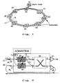
- Fig. 1 demonstrates a Self-Healing Ring comprising two sets of optical fibers, 10 and 11, connecting a number of subnodes 21-27 into a ring structure, which in turn is connected to a main node 20 (OXC) and to a DXC/HUB 15.
- OXC main node 20
- a DXC/HUB 15 DXC/HUB 15.
- each subnode is designated as a number n Optical Add Drop Multiplexor (OADMn).
- An OADM comprises at least two monitor points 31 and 32, two selective optical filters 33 and 34, an optical 2x2 switch 35 and two optical amplifiers 37 and 38 as is illustrated in Fig. 2.
- Two optical passive couplers may be used to give access to both fibers if just one transmitter and one receiver are used e.g. Line TeRMinal.
- each subnode is according to the state of the art including its own processing facility (not shown) handling the exchange of signals to and from the network.
- Each node 21-27 is capable of creating alarm signals I 1 and I 2 serving as a basis for switching decisions necessarily made after a fiber or a node break-down.
- a fraction of the signal is drawn off at two monitoring points 31, 32 near each node.
- Both the working ring 10 and the standby ring 11 are supervised by at least one such monitor point, as demonstrated in Fig. 2.
- the alarm signals I 1 and I 2 are derived from monitoring means M 1 and M 2 , representing simple detectors judging if there is a signal on the fiber or not, i.e. whether the specific fiber section is unbroken or not.
- M 1 detects a signal loss on the working ring 10 it generates and sends an alarm signal I 1 .
- M 2 creates an alarm signal I 2 when loss of signal occurs on the stand-by ring 11.
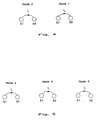
- the nodes appear in different conditions, characterized by the way the optical switch is configured and the way the optical filter is activated, for instance, which of the inputs and outputs that have been interconnected.
- the four fundamental node states are:
- the nodes Under normal conditions (unbroken fibers and no malfunction of the nodes), the nodes are transmitting on the working ring 10. Yet the monitoring system requires a signal on the fiber in order to tell if it is broken or not. Therefore we may, for instance, make use of a distributive signal or the amplified spontaneous emission from the optical amplifiers 38 in an additional way by sending it on the standby ring 11 for monitoring purposes.
- Fig. 2 shows a more detailed block diagram of a subnode having optical filters 33, 34, a supervisory block as well as an optical 2x2 switch block 35 having two inputs and two outputs.
- the optical switch block will be controlled by the different available node states.
- the table in Fig. 3 presents a list of the possible node states S1-S4 in combination with their corresponding optical switch configurations and monitor signals.
- Fig. 1 shows a block diagram of a self-healing ring.
- a fiber breakage occurring on the working ring 10 between subnode 21 (OADM 1 ) and subnode 22 (OADM 2 ) brings about the following events:
- a fiber breakage taking place at some other point in the ring would cause the same events in the same sequence.
- a fiber breakage at the stand-by ring 11 would be detected by a node and then be reported to the management system. No further proceedings are to be taken in this case.
- the OADM structure according to the present invention offers a greater simplicity for adding and removing nodes in an existing optical network.
- An Optical Add Drop Multiplexing node in an optical network may of course be designed in numerous ways, by using different components than what has been indicated here in an illustrative embodiment, without deviating from the spirit, object and scope of the present disclosed method and system defined by the attached claims.
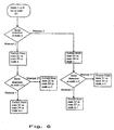
- Fig. 6 is shown a flow chart demonstrating folding of an WDM Self-Healing Ring. Initially all nodes are set in state S1 and will remain in this state until a failure occurs. If a failure occurs at node n monitor M 1 detects a signal loss (no signal on the working ring 10) and transmits an alarm signal I 1 to the switch 35 of the node. The switch folds the ring in front, i.e. turns the node n to state S4.
- no signal is transmitted on the stand-by ring 11 at node n-1.
- This causes an alarm signal I 2 to be activated at node n-1 indicating a signal loss whereby this alarm signal I 2 will be transferred to a processor card in in node n-1.
- node n-1 folds behind, i.e. turns to state S3. This is indicated by the portion to the right in Fig. 6.
- the other nodes detect no difference.
- Fig. 7 is shown a flow chart demonstrating line switching of a WDM Self-Healing Ring. Initially all nodes are set in state S1 and will remain there until a failure occurs.
- a fiber breakage at the stand-by ring 11 would by the detecting node be reported to the management system. No further proceedings are to be taken in this case.
Landscapes
- Engineering & Computer Science (AREA)
- Computer Networks & Wireless Communication (AREA)
- Signal Processing (AREA)
- Optical Communication System (AREA)
- Small-Scale Networks (AREA)
- Monitoring And Testing Of Transmission In General (AREA)
- Light Guides In General And Applications Therefor (AREA)
- Mechanical Coupling Of Light Guides (AREA)
- Semiconductor Lasers (AREA)
- Optical Fibers, Optical Fiber Cores, And Optical Fiber Bundles (AREA)
- Eyeglasses (AREA)
Claims (10)
- Verfahren zum Konfigurieren von Unterknoten in einem optischen Netzring gegen sowohl Knoten- als auch Faser-Fehler, wobei das Netz einen Arbeitsring (10) und einem Bereitschaftsring (11) umfasst, und jeder Unterknoten Überwachungspunkte (31, 32) und Umschalteinrichtungen (35) einschließt, und wobei das Verfahren die Schritte umfasst:dadurch gekennzeichnet, dass jeder Unterknoten weiter selektive optische Filtereinrichtungen (33, 34) und optische Verstärkereinrichtungen (37, 38) einschließt, dass die Umschalteinrichtungen optische 2x2-Umschalteinrichtungen (35) sind, und dass die möglichen neuen Zustände ein Falten eines Rings vor oder hinter einem Unterknoten und ein Leitungsumschalten einschließen.Überwachen von Eingängen bzw. Ausgängen jedes Unterknotens (OADMn) für die Arbeits- und Überwachungsringe (10, 11) mittels Überwachungseinrichtungen (M1, M2), die die Überwachungspunkte überwachen,Erzeugen, mittels der Überwachungseinrichtungen (M1, M2), eines Alarmsignals (I1, I2) auf eine Erfassung eines Signalverlusts an einem Unterknoten (OADMn) hin,Einstellen, als eine Antwort auf das Alarmsignal, des Zustands des Unterknotens (OADMn), der das Alarmsignal (I1, I2) herbeiführt, von einem ersten Zustand (S1) in einen einer Anzahl möglicher neuer Zustände (S2-S4) als eine Funktion des erzeugten Alarmsignals (I1, I2),Auswählen einer Umschaltkonfiguration für den Unterknoten (OADMn) gemäß des neuen Zustands (S2-S4),
- Verfahren nach Anspruch 1, umfassend den zusätzlichen Schritt eines Faltens eines Rings vor dem Unterknoten (OADMn), als eine alternative Maßnahme, wenn eine Überwachungseinrichtung (M1) ein Alarmsignal (I1) erzeugt, wodurch der Unterknoten (OADMn) von einem ersten Zustand (S1) in einen vierten Zustand (S4) gesetzt wird, und der Unterknoten nicht mehr irgendein Signal auf den Ring bei dem Unterknoten (OADMn) empfängt, wodurch ein Alarmsignal (I2) für einen vorangehenden Unterknoten (OADMn-1) erzeugt werden wird, und der vorangehende Unterknoten (OADMn-1) von einem ersten Zustand (S1) auf einen dritten Zustand (S3) umgeschaltet werden wird.
- Verfahren nach Anspruch 1, umfassend den zusätzlichen Schritt eines Faltens eines Rings hinter dem Unterknoten (OADMn), als eine alternative Maßnahme, wenn eine Überwachungseinrichtung (M2) ein Alarmsignal (I2) erzeugt, wodurch der Unterknoten (OADMn) von einem ersten Zustand (S1) auf einen dritten Zustand (S3) gesetzt wird, und der Unterknoten irgendein Signal auf dem Ring bei dem Unterknoten (OADMn) nicht mehr übertragen wird, wodurch ein Alarmsignal (I1) bei einem nächsten Unterknoten (OADMn+1) erzeugt werden wird, und der nächste Unterknoten (OADMn+1) von einem ersten Zustand (S1) auf einen vierten Zustand (S4) umgeschaltet werden wird.
- Verfahren nach Anspruch 1, umfassend den zusätzlichen Schritt eines Leitungsumschaltens des Arbeitsrings (10), als eine weitere alternative Maßnahme gegen eine unterbrochene Faser zwischen dem Unterknoten (OADMn) und den vorangehenden Unterknoten (OADMn-1), wodurch ein Filter auf dem Bereitschaftsring (11) durch ein Verbringen des Unterknotens (OADMn) von einem ersten Zustand (S1) in einen zweiten Zustand (S2) aktiviert werden wird, der wiederum den vorangehenden Knoten (OADMn-1) und einen nächsten Unterknoten (OADMn-1) von einem ersten Zustand (S1) in einen zweiten Zustand (S2) verbringen wird, wobei dadurch der Bereitschaftsring als eine Umgehung verwendet wird.
- Verfahren nach Anspruch 1, umfassend den zusätzlichen Schritt eines Einstellens eines vorbesetzten Werts für jeden Unterknoten (OADMn), ein "alles Durchlassen" für die optischen Filter (33, 34) zu sein, und ein Einstellen des Knotens in einen ersten Knotenzustand (S1) zum Durchlassen der optischen Signale dort hindurch.
- System von Unterknoten in einem optischen Netzring, der gegen sowohl Knoten- als auch Faserfehler konfiguriert ist, wobei das Netz einen Arbeitsring (10) und einen Bereitschaftsring (11) umfasst und jeder Unterknoten Überwachungspunkte (31, 32) und Umschalteinrichtungen (35) einschließt, wobei das System weiter umfasst:Überwachungseinrichtungen (M1, M2) zum Überwachen von Eingängen bzw. Ausgängen jedes Unterknotens (OADMn) für die Arbeits- und Überwachungsringe (10, 11) mittels einer Überwachung der Überwachungspunkte,eine Einrichtung zum Erzeugen, durch die Monitoreinrichtungen (M1, M2), eines Alarmsignals (I1, I2) auf eine Erfassung eines Signalverlusts an einem Unterknoten (OADMn) hin,eine Einrichtung zum Einstellen, als eine Antwort auf das Alarmsignal, des Zustands des Unterknotens (OADMn), der das Alarmsignal (I1, I2) herbeiführt, von einem ersten Zustand (S1) in einen eine Anzahl möglicher neuer Zustände (S2-S4) als eine Funktion des erzeugten Alarmsignals (I1, I2), undeine Einrichtung zum Auswählen einer Umschaltkonfiguration für den Unterknoten (OADMn) gemäß dem eingestellten neuen Zustand (S2-S4), dadurch gekennzeichnet, dass jeder Unterknoten weiter selektive optische Filtereinrichtungen (33, 34) und optische Verstärkereinrichtungen (37, 38) einschließt, dass die Umschalteinrichtungen optische 2x2-Umschalteinrichtungen sind und dass die möglichen neuen Zustände ein Falten eines Rings vor oder hinter einem Unterknoten und ein Leitungsumschalten einschließen.
- System nach Anspruch 6, wobei das System angeordnet ist, einen Ring vor dem Unterknoten (OADMn) zu falten, wenn eine Überwachungseinrichtung (M1) ein Alarmsignal (I1) erzeugt, wodurch der Unterknoten (OADMn) von einem ersten Zustand (S1) in einen vierten Zustand (S4) gesetzt wird, und der Unterknoten nicht mehr irgendein Signal auf dem Ring an dem Unterknoten (OADMn) empfangen wird, wodurch ein Alarmsignal (I2) zu einem vorangehenden Unterknoten (OADMn-1) erzeugt werden wird, und der vorangehende Unterknoten (OADMn-1) von einem ersten Zustand (S1) in einen dritten Zustand (S3) umgeschaltet werden wird.
- System nach Anspruch 6, wobei das System angeordnet ist, einen Ring hinter dem Unterknoten (OADMn) als eine alternative Maßnahme zu falten, wenn eine Überwachungseinrichtung (M2) ein Alarmsignal (I2) erzeugt, wodurch der Unterknoten (OADMn) von einem ersten Zustand (S1) in einen dritten Zustand (S3) gesetzt wird, und der Unterknoten nicht mehr irgendein Signal auf den Ring bei dem Unterknoten (OADMn) senden wird, wodurch ein Alarmsignal (I1) an einem nächsten Unterknoten (OADMn+1) erzeugt werden wird, und der nächste Unterknoten (OADMn+1) von einem ersten Zustand (S1) in einen vierten Zustand (S4) geschaltet werden wird.
- System nach Anspruch 6, wobei das System angeordnet ist, den Arbeitsring (10), als eine weitere alternative Maßnahme gegen eine unterbrochene Faser zwischen dem Unterknoten (OADMn) und dem vorangehenden Unterknoten (OADMn-1) durchzuschalten, wodurch ein Filter auf dem Bereitschaftsring (10) durch ein Verbringen des Unterknotens (OADMn) von einem ersten Zustand (S1) in einen zweiten Zustand (S2) aktiviert werden wird, was wiederum den vorangehenden Unterknoten (OADMn-1) und einen nächsten Unterknoten (OADMn+1) von einem ersten Zustand (S1) in einen zweiten Zustand (S2) verbringen wird, wobei der Bereitschaftsring als eine Umgehung verwendet wird.
- System nach Anspruch 6, wobei ein vorbesetzter Wert für jeden Unterknoten (OADMn) auf "alles Durchlassen" für die optischen Filter (33, 34) gesetzt ist, und der Knoten in einem ersten Knotenzustand (S1) zum Durchleiten der optischen Signale dort hindurch eingestellt wird.
Applications Claiming Priority (3)
| Application Number | Priority Date | Filing Date | Title |
|---|---|---|---|
| SE9404446 | 1994-12-21 | ||
| SE9404446A SE514658C2 (sv) | 1994-12-21 | 1994-12-21 | Nodarkitektur för tillämpning av optisk optimering (OADM) |
| PCT/SE1995/001490 WO1996019884A1 (en) | 1994-12-21 | 1995-12-11 | Optical add drop multiplex (oadm) |
Publications (2)
| Publication Number | Publication Date |
|---|---|
| EP0799536A1 EP0799536A1 (de) | 1997-10-08 |
| EP0799536B1 true EP0799536B1 (de) | 2003-12-10 |
Family
ID=20396414
Family Applications (1)
| Application Number | Title | Priority Date | Filing Date |
|---|---|---|---|
| EP95941956A Expired - Lifetime EP0799536B1 (de) | 1994-12-21 | 1995-12-11 | Optisches ein-/ausfügemultiplex |
Country Status (12)
| Country | Link |
|---|---|
| US (1) | US6097516A (de) |
| EP (1) | EP0799536B1 (de) |
| JP (1) | JPH10511821A (de) |
| KR (1) | KR100333253B1 (de) |
| CN (1) | CN1101626C (de) |
| AT (1) | ATE256358T1 (de) |
| AU (1) | AU697436B2 (de) |
| CA (1) | CA2207553A1 (de) |
| DE (1) | DE69532296T2 (de) |
| FI (1) | FI112136B (de) |
| SE (1) | SE514658C2 (de) |
| WO (1) | WO1996019884A1 (de) |
Families Citing this family (28)
| Publication number | Priority date | Publication date | Assignee | Title |
|---|---|---|---|---|
| IT1283372B1 (it) | 1996-07-31 | 1998-04-17 | Pirelli Cavi S P A Ora Pirelli | Dispositivo per l'inserimento e l'estrazione di segnali ottici |
| JPH10126350A (ja) * | 1996-10-15 | 1998-05-15 | Nec Corp | 光ネットワーク、光分岐挿入ノードおよび障害回復方式 |
| SE9702685D0 (sv) * | 1997-07-11 | 1997-07-11 | Ericsson Telefon Ab L M | Self-healing ring network and a method for fault detection and rectifying |
| JPH1198077A (ja) * | 1997-09-16 | 1999-04-09 | Nec Corp | 光波ネットワークシステム |
| US6396852B1 (en) * | 1997-11-18 | 2002-05-28 | Jane Marie Simmons | Ring bundling in the design of rings for telecommunications networks |
| US6020986A (en) * | 1997-11-21 | 2000-02-01 | Jds Uniphase Corporation | Programmable add-drop module for use in an optical circuit |
| US5974207A (en) * | 1997-12-23 | 1999-10-26 | Lucent Technologies, Inc. | Article comprising a wavelength-selective add-drop multiplexer |
| US6400476B1 (en) | 1997-12-31 | 2002-06-04 | Cisco Photonics Italy S.R.L. | Method and apparatus for transparent optical communication with two-fiber bidirectional ring with autoprotection and management of low priority traffic |
| EP1030480A3 (de) * | 1999-02-19 | 2002-06-12 | JDS Uniphase Inc. | Konfigurierbare optische Schaltung |
| GB2347809B (en) * | 1999-03-12 | 2001-06-20 | Marconi Comm Ltd | Signal transmission system |
| US8554076B1 (en) * | 1999-10-04 | 2013-10-08 | At&T Intellectual Property Ii, L.P. | Methods and systems for constructing optical networks |
| US20010038473A1 (en) * | 2000-03-10 | 2001-11-08 | Ming-Jun Li | Devices and methods for controlling protection switching in an optical channel shared protection ring |
| US6288812B1 (en) | 2000-11-03 | 2001-09-11 | Seneca Networks | Bidirectional WDM optical communication network with optical bridge between bidirectional optical waveguides |
| US20020159392A1 (en) * | 2001-04-25 | 2002-10-31 | Adc Telecommunications Israel Ltd. | Simplified ATM ring protection for access networks |
| IL143368A (en) * | 2001-05-24 | 2006-07-05 | Shlomo Orbach | Multiply up and down optical signals |
| US7272307B2 (en) * | 2001-05-25 | 2007-09-18 | Tellabs Operations, Inc. | Virtual protection channel for fiber optic ring network |
| CA2353307A1 (fr) | 2001-07-13 | 2003-01-13 | Carmen Parent | Appareil et procede pour le traitement des effluents gazeux |
| CN100346588C (zh) * | 2001-10-29 | 2007-10-31 | 上海贝尔有限公司 | 用于波分复用光网的双纤双向通道/复用段倒换环系统 |
| IL146822A0 (en) | 2001-11-29 | 2002-07-25 | Lightscape Networks Ltd | Method and device for expanding communication networks |
| US7372804B2 (en) * | 2002-01-11 | 2008-05-13 | Nec Corporation | Multiplex communication system and method |
| CA2405635A1 (en) | 2002-09-27 | 2004-03-27 | C02 Solution Inc. | A process and a plant for the production of useful carbonated species and for the recycling of carbon dioxide emissions from power plants |
| JP2005352202A (ja) * | 2004-06-10 | 2005-12-22 | Sumitomo Electric Ind Ltd | 光回路、光合波器及び光分波器 |
| US7286763B2 (en) * | 2004-06-16 | 2007-10-23 | Lucent Technologies Inc. | Optical add/drop multiplexer having a banded channel configuration |
| US20050281295A1 (en) * | 2004-06-16 | 2005-12-22 | Fishman Daniel A | Optical add/drop multiplexer having an alternated channel configuration |
| US8683044B2 (en) | 2005-03-16 | 2014-03-25 | Vonage Network Llc | Third party call control application program interface |
| JP4855209B2 (ja) * | 2006-10-19 | 2012-01-18 | 富士通株式会社 | 光伝送装置 |
| US8553534B2 (en) | 2007-12-21 | 2013-10-08 | Telecom Italia S.P.A. | Protecting an ethernet network having a ring architecture |
| WO2015045303A1 (ja) * | 2013-09-26 | 2015-04-02 | 日本電気株式会社 | 光受信装置、光送信装置、光通信システム、光通信方法及びプログラムが記憶された記憶媒体 |
Family Cites Families (19)
| Publication number | Priority date | Publication date | Assignee | Title |
|---|---|---|---|---|
| GB1229149A (de) * | 1969-07-28 | 1971-04-21 | ||
| US4190821A (en) * | 1978-10-02 | 1980-02-26 | Burroughs Corporation | Self-healing loop communications system |
| US4704713A (en) * | 1985-12-26 | 1987-11-03 | Bell Communications Research, Inc. | Optical ring network |
| US4829512A (en) * | 1986-08-26 | 1989-05-09 | Nec Corporation | Loop-back control apparatus for a loop network having duplicate optical fiber transmission lines |
| US5229875A (en) * | 1989-05-30 | 1993-07-20 | Glista Andrew S | Fault-tolerant fiber optic coupler/repeater for use in high speed data transmission and the like |
| US4797879A (en) * | 1987-06-05 | 1989-01-10 | American Telephone And Telegraph Company At&T Bell Laboratories | Packet switched interconnection protocols for a star configured optical lan |
| BR8901185A (pt) * | 1989-03-09 | 1990-10-16 | Brasil Compressores Sa | Sistema de descarga para compressor rotativo de pistao rolante |
| US5185736A (en) * | 1989-05-12 | 1993-02-09 | Alcatel Na Network Systems Corp. | Synchronous optical transmission system |
| US5208692A (en) * | 1989-06-29 | 1993-05-04 | Digital Equipment Corporation | High bandwidth network based on wavelength division multiplexing |
| US5003531A (en) * | 1989-08-11 | 1991-03-26 | Infotron Systems Corporation | Survivable network using reverse protection ring |
| SE469149B (sv) * | 1990-12-07 | 1993-05-17 | Ellemtel Utvecklings Ab | Optisk vaeljare, optisk korskopplare och saett att omkoppla grupper av optiska signaler |
| GB9202666D0 (en) * | 1992-02-07 | 1992-03-25 | Madge Networks Ltd | Communication system |
| US5278824A (en) * | 1992-06-02 | 1994-01-11 | At&T Bell Laboratories | Dual hubbing in a bidirectional line-switched ring transmission system |
| US5442623A (en) * | 1992-08-17 | 1995-08-15 | Bell Communications Research, Inc. | Passive protected self healing ring network |
| US5335104A (en) * | 1992-10-22 | 1994-08-02 | Laser Precision Corp. | Method of detecting breaks in multi-drop feeder systems |
| JP3347382B2 (ja) * | 1993-02-23 | 2002-11-20 | 株式会社東芝 | 光アド・ドロップ波長多重分離装置 |
| EP0651528B1 (de) * | 1993-10-29 | 2003-01-22 | Siemens Aktiengesellschaft | Optisches, transparentes Ringnetz mit Ersatzschaltwegen |
| ATE270012T1 (de) * | 1993-10-29 | 2004-07-15 | Siemens Ag | Optisches, transparentes ringnetz mit auskoppelung eines signales einer wellenlänge in einem oder mehreren ringknoten |
| US5680235A (en) * | 1995-04-13 | 1997-10-21 | Telefonaktiebolaget Lm Ericsson | Optical multichannel system |
-
1994
- 1994-12-21 SE SE9404446A patent/SE514658C2/sv not_active IP Right Cessation
-
1995
- 1995-12-11 EP EP95941956A patent/EP0799536B1/de not_active Expired - Lifetime
- 1995-12-11 DE DE69532296T patent/DE69532296T2/de not_active Expired - Lifetime
- 1995-12-11 KR KR1019970704152A patent/KR100333253B1/ko not_active Expired - Lifetime
- 1995-12-11 CN CN95196920A patent/CN1101626C/zh not_active Expired - Lifetime
- 1995-12-11 CA CA002207553A patent/CA2207553A1/en not_active Abandoned
- 1995-12-11 WO PCT/SE1995/001490 patent/WO1996019884A1/en not_active Ceased
- 1995-12-11 JP JP8519715A patent/JPH10511821A/ja active Pending
- 1995-12-11 US US08/849,693 patent/US6097516A/en not_active Expired - Lifetime
- 1995-12-11 AU AU43201/96A patent/AU697436B2/en not_active Expired
- 1995-12-11 AT AT95941956T patent/ATE256358T1/de not_active IP Right Cessation
-
1997
- 1997-06-19 FI FI972666A patent/FI112136B/fi not_active IP Right Cessation
Also Published As
| Publication number | Publication date |
|---|---|
| US6097516A (en) | 2000-08-01 |
| ATE256358T1 (de) | 2003-12-15 |
| FI972666A0 (fi) | 1997-06-19 |
| CA2207553A1 (en) | 1996-06-27 |
| DE69532296D1 (de) | 2004-01-22 |
| SE9404446D0 (sv) | 1994-12-21 |
| SE9404446L (sv) | 1996-06-22 |
| SE514658C2 (sv) | 2001-03-26 |
| EP0799536A1 (de) | 1997-10-08 |
| AU4320196A (en) | 1996-07-10 |
| FI972666A7 (fi) | 1997-06-19 |
| CN1170485A (zh) | 1998-01-14 |
| DE69532296T2 (de) | 2004-10-21 |
| FI112136B (fi) | 2003-10-31 |
| AU697436B2 (en) | 1998-10-08 |
| JPH10511821A (ja) | 1998-11-10 |
| KR100333253B1 (ko) | 2002-11-20 |
| CN1101626C (zh) | 2003-02-12 |
| WO1996019884A1 (en) | 1996-06-27 |
Similar Documents
| Publication | Publication Date | Title |
|---|---|---|
| EP0799536B1 (de) | Optisches ein-/ausfügemultiplex | |
| US6295146B1 (en) | System and method for sharing a spare channel among two or more optical ring networks | |
| US6701085B1 (en) | Method and apparatus for data transmission in the wavelength-division multiplex method in an optical ring network | |
| US5933258A (en) | Optical communication system | |
| JP3551407B2 (ja) | 波長多重光伝送システム | |
| US5870212A (en) | Self-healing optical network | |
| EP1004185B1 (de) | Verfahren und system zur verbindung von ringnetzen | |
| US5982517A (en) | Method and system for service restoration in optical fiber communication networks | |
| WO1987004029A1 (en) | Optical ring network | |
| CA2294828C (en) | Self-healing ring network and a method for fault detection and rectifying | |
| US6697546B2 (en) | Optical node system and switched connection method | |
| CN1416234A (zh) | 用于波分复用光网的双纤双向通道/复用段倒换环系统 | |
| EP1048134A1 (de) | Vorrichtung und verfahren zur verbesserung der robustheit eines optischen ringnetzwerks | |
| JP3354116B2 (ja) | 波長多重光通信網 | |
| JP2003046456A (ja) | 光伝送ネットワークシステムおよび光伝送ネットワークシステムの障害監視方法 | |
| JP3257772B2 (ja) | 波長多重通信網における不要警報抑止方法および装置 | |
| JP3399901B2 (ja) | 光伝送ネットワークシステム | |
| JP2798631B2 (ja) | Sdhリング型網のパス切替方式 | |
| MXPA00006961A (en) | System and method for sharing a spare channel among two or more optical ring networks |
Legal Events
| Date | Code | Title | Description |
|---|---|---|---|
| PUAI | Public reference made under article 153(3) epc to a published international application that has entered the european phase |
Free format text: ORIGINAL CODE: 0009012 |
|
| 17P | Request for examination filed |
Effective date: 19970524 |
|
| AK | Designated contracting states |
Kind code of ref document: A1 Designated state(s): AT CH DE ES FR GB GR IT LI NL |
|
| 17Q | First examination report despatched |
Effective date: 20020218 |
|
| GRAH | Despatch of communication of intention to grant a patent |
Free format text: ORIGINAL CODE: EPIDOS IGRA |
|
| GRAS | Grant fee paid |
Free format text: ORIGINAL CODE: EPIDOSNIGR3 |
|
| GRAA | (expected) grant |
Free format text: ORIGINAL CODE: 0009210 |
|
| AK | Designated contracting states |
Kind code of ref document: B1 Designated state(s): AT CH DE ES FR GB GR IT LI NL |
|
| PG25 | Lapsed in a contracting state [announced via postgrant information from national office to epo] |
Ref country code: NL Free format text: LAPSE BECAUSE OF FAILURE TO SUBMIT A TRANSLATION OF THE DESCRIPTION OR TO PAY THE FEE WITHIN THE PRESCRIBED TIME-LIMIT Effective date: 20031210 Ref country code: LI Free format text: LAPSE BECAUSE OF FAILURE TO SUBMIT A TRANSLATION OF THE DESCRIPTION OR TO PAY THE FEE WITHIN THE PRESCRIBED TIME-LIMIT Effective date: 20031210 Ref country code: IT Free format text: LAPSE BECAUSE OF FAILURE TO SUBMIT A TRANSLATION OF THE DESCRIPTION OR TO PAY THE FEE WITHIN THE PRESCRIBED TIME-LIMIT;WARNING: LAPSES OF ITALIAN PATENTS WITH EFFECTIVE DATE BEFORE 2007 MAY HAVE OCCURRED AT ANY TIME BEFORE 2007. THE CORRECT EFFECTIVE DATE MAY BE DIFFERENT FROM THE ONE RECORDED. Effective date: 20031210 Ref country code: FR Free format text: LAPSE BECAUSE OF FAILURE TO SUBMIT A TRANSLATION OF THE DESCRIPTION OR TO PAY THE FEE WITHIN THE PRESCRIBED TIME-LIMIT Effective date: 20031210 Ref country code: CH Free format text: LAPSE BECAUSE OF FAILURE TO SUBMIT A TRANSLATION OF THE DESCRIPTION OR TO PAY THE FEE WITHIN THE PRESCRIBED TIME-LIMIT Effective date: 20031210 Ref country code: AT Free format text: LAPSE BECAUSE OF FAILURE TO SUBMIT A TRANSLATION OF THE DESCRIPTION OR TO PAY THE FEE WITHIN THE PRESCRIBED TIME-LIMIT Effective date: 20031210 |
|
| REG | Reference to a national code |
Ref country code: GB Ref legal event code: FG4D |
|
| REG | Reference to a national code |
Ref country code: CH Ref legal event code: EP |
|
| REF | Corresponds to: |
Ref document number: 69532296 Country of ref document: DE Date of ref document: 20040122 Kind code of ref document: P |
|
| PG25 | Lapsed in a contracting state [announced via postgrant information from national office to epo] |
Ref country code: GR Free format text: LAPSE BECAUSE OF FAILURE TO SUBMIT A TRANSLATION OF THE DESCRIPTION OR TO PAY THE FEE WITHIN THE PRESCRIBED TIME-LIMIT Effective date: 20040310 |
|
| PG25 | Lapsed in a contracting state [announced via postgrant information from national office to epo] |
Ref country code: ES Free format text: LAPSE BECAUSE OF FAILURE TO SUBMIT A TRANSLATION OF THE DESCRIPTION OR TO PAY THE FEE WITHIN THE PRESCRIBED TIME-LIMIT Effective date: 20040321 |
|
| RAP2 | Party data changed (patent owner data changed or rights of a patent transferred) |
Owner name: TELEFONAKTIEBOLAGET LM ERICSSON (PUBL) |
|
| NLV1 | Nl: lapsed or annulled due to failure to fulfill the requirements of art. 29p and 29m of the patents act | ||
| REG | Reference to a national code |
Ref country code: CH Ref legal event code: PL |
|
| PLBE | No opposition filed within time limit |
Free format text: ORIGINAL CODE: 0009261 |
|
| STAA | Information on the status of an ep patent application or granted ep patent |
Free format text: STATUS: NO OPPOSITION FILED WITHIN TIME LIMIT |
|
| 26N | No opposition filed |
Effective date: 20040913 |
|
| EN | Fr: translation not filed | ||
| PGFP | Annual fee paid to national office [announced via postgrant information from national office to epo] |
Ref country code: GB Payment date: 20141229 Year of fee payment: 20 |
|
| PGFP | Annual fee paid to national office [announced via postgrant information from national office to epo] |
Ref country code: DE Payment date: 20141230 Year of fee payment: 20 |
|
| REG | Reference to a national code |
Ref country code: DE Ref legal event code: R071 Ref document number: 69532296 Country of ref document: DE |
|
| REG | Reference to a national code |
Ref country code: GB Ref legal event code: PE20 Expiry date: 20151210 |
|
| PG25 | Lapsed in a contracting state [announced via postgrant information from national office to epo] |
Ref country code: GB Free format text: LAPSE BECAUSE OF EXPIRATION OF PROTECTION Effective date: 20151210 |