EP0799560A2 - Conduite pour l'air de sortie d'un distributeur pneumatique - Google Patents
Conduite pour l'air de sortie d'un distributeur pneumatique Download PDFInfo
- Publication number
- EP0799560A2 EP0799560A2 EP97102933A EP97102933A EP0799560A2 EP 0799560 A2 EP0799560 A2 EP 0799560A2 EP 97102933 A EP97102933 A EP 97102933A EP 97102933 A EP97102933 A EP 97102933A EP 0799560 A2 EP0799560 A2 EP 0799560A2
- Authority
- EP
- European Patent Office
- Prior art keywords
- exhaust air
- conveyed
- line
- air line
- shut
- Prior art date
- Legal status (The legal status is an assumption and is not a legal conclusion. Google has not performed a legal analysis and makes no representation as to the accuracy of the status listed.)
- Granted
Links
Images


Classifications
-
- A—HUMAN NECESSITIES
- A01—AGRICULTURE; FORESTRY; ANIMAL HUSBANDRY; HUNTING; TRAPPING; FISHING
- A01C—PLANTING; SOWING; FERTILISING
- A01C7/00—Sowing
- A01C7/08—Broadcast seeders; Seeders depositing seeds in rows
- A01C7/087—Tramlining
-
- A—HUMAN NECESSITIES
- A01—AGRICULTURE; FORESTRY; ANIMAL HUSBANDRY; HUNTING; TRAPPING; FISHING
- A01C—PLANTING; SOWING; FERTILISING
- A01C7/00—Sowing
- A01C7/08—Broadcast seeders; Seeders depositing seeds in rows
- A01C7/081—Seeders depositing seeds in rows using pneumatic means
- A01C7/084—Pneumatic distribution heads for seeders
Definitions
- the invention relates to an exhaust air line for a pneumatically operating distribution machine according to the preamble of the main claim.
- Pneumatically operating distribution machines e.g. B. for seeds, fertilizers and. Like., have long been known, for. B. from the utility model G 94 10 912.5.
- the material to be conveyed is fed pneumatically to a distributor which distributes the material to be conveyed to individual distributor lines which lead to spreading devices, for example coulters.
- Locking means can be used to block individual distribution lines in order to prevent the delivery of the material to be conveyed onto the respective delivery devices in order, for. B. in the case of a seeder to create tramlines in which no seeds are to be deposited.
- the material to be conveyed which is fed to a blocked distribution line, is discharged via a discharge nozzle.
- This discharge nozzle is in turn connected to a return line which leads the conveyed material back into the conveying area of the conveyor, ie e.g. in the storage tank of the material to be conveyed or directly to the conveyor.
- the derived conveyed material is returned directly to the pneumatic conveyor system, whereby it can be disadvantageous that the introduction of the derived material into the conveying flow changes the sowing quantity of the still open distribution lines, so that readjustment of the setting value of the metering device may be required.
- the material to be conveyed is returned when the distributor line is shut off, both the material to be conveyed and the conveying air of the pneumatic distributor machine are discharged.
- the material to be conveyed is returned back into the storage tank of the material to be conveyed, especially if a collector is used which is surrounded by the material to be conveyed, it can happen that the additionally conveyed conveying air in the storage tank leads to the formation of air accumulations or air bubbles, which a prevents optimal conveyance of the conveyed material from the tank. It can be particularly disruptive if the air bubbles formed by the conveyed air are in the vicinity of the metering device located in the tank and incorrect dosing occurs. If the conveying air is returned to the pneumatic conveying system, it can lead to an undesirable change in the conveying flow conditions, which can lead to a change in the application accuracy.
- the invention has for its object to further develop the generic exhaust air line so that even with a large number of blocked distribution lines, a precisely adjustable and undisturbed conveying and distribution of conveyed material is achieved by the distributor on the corresponding dispensing devices.
- a connector 1 for a distributor is shown, only one side half of the connector is shown in Fig. 1, and on this side half a further side half can be mounted to form the connector 1 in its entirety.
- the connector 1 has a connection 2, which can be mounted on the distributor and has an end connection 3, to which, for. B. by means of a clamp, a flexible pipe 31 can be mounted, which leads to spreading devices, for example a coulter, a fertilizer spreader or the like.
- a locking flap 4 is arranged, which is shown in its open position is and the flow of the conveyed material from port 2 to port 3 not obstructed. This locking flap 4 can be pivoted downward so that it is in its locked position.
- this return line 6 returning the conveyed material when the shut-off flap 4 is closed, ie. H. the material to be conveyed back into the tank or into the pneumatic feed system of the material to be conveyed to the distributor. This ensures that even when the shut-off flap 4 is closed, the conveyed material is discharged and is not distributed to the adjacent lines.
- the return line 6 is not only z. B. to understand tubular element, but relates to the entire route of the conveyed material from the blocking means to the delivery of the returned material into the renewed conveying cycle, d. H. e.g. B. up to a metering device or up to a conveyor.
- an exhaust air line 8 starts and opens in the area of the end connection 3 of the connector downstream of the shut-off flap 4. Via this exhaust air line 8, the returned material and the conveyed air are separated. While the material to be conveyed, such as seed, falls down along the return line 6 due to gravity and inertia, the pneumatic conveying air that is no longer required can bypass the shut-off flap 4 via the exhaust air line 8 in the sense of a bypass line and is then connected via the end connection 3 and the distribution lines via the dispensing devices given without it can hinder the further promotion or distribution of the goods.
- FIG. 1 illustrates the possible flows and rivers.
- Arrows 23 show the conveyed material and conveyed air flow when the shut-off flap 4;
- Arrows 24 show the derived conveyed-air mixture when the shut-off valve 4 is closed and arrows 25 show the air discharged via the bypass line when the shut-off valve 4 is also closed.
- Fig. 1 offers the particular advantage that a very compact design is achieved, since both the connector 1 and the exhaust duct 8 form a component, whereby the manufacturing costs and the assembly costs are minimized. So z. B. a separate assembly of the exhaust pipe 8 is no longer necessary.
- a swivel flap 9 is provided, which is designed to be swivelable via a joint 10.
- the actuation of the joint 10 can be carried out, for example, via a lever (not shown) or via electronic servomotors or the like.
- This pivoting flap 9 enables the amount of the conveyed material to be influenced, which is conveyed via the exhaust air line 8 in the direction of the spreading means (coulters or the like). In the position shown in FIG. 1, all material to be conveyed is discharged via the return line 6 and only exhaust air is discharged via the exhaust air line 8.
- the swivel flap 9 continues inwards, ie in the direction the exhaust air line 8 is set, a certain percentage of the conveyed material gets into the exhaust air line, for. B. 5%, and is then applied via the distribution lines via the application means.
- This can be a desired effect, e.g. B. in the creation of tramlines from time to time to promote a seed in order to achieve a reduction in erosion on the otherwise uncultivated tramlines by the now sown plants.
- the length of the swivel flap 9 variable or to offer different lengths of the swivel flap 9, which can then be used by the user according to his wishes.
- the swing flap 9 can of course also be used where the exhaust air line 8 does not run to the distribution line.
- the opening of the exhaust air line 8 at the end connection 3 or to the distributor line is designed such that the cross section of the end connection 3 before the opening of the exhaust air line 8 is smaller than the cross section of the end connection 3 downstream of the opening of the exhaust air line 8.
- the exhaust air line 8 can open, for example, in the upper region of the conveyed goods tank, so that the conveyed air which is not required can escape there.
- the exhaust air line 8 it is possible for the exhaust air line 8 to be led through the tank wall to the outside, where the conveying air can escape without hindering the further conveying of conveyed goods.
- the return lines 6 can be led to a collector 14 shown in FIG. 2, which has a plurality of connections 15 to 20, wherein a return line 6 can be arranged on each connection. Unused connections of the collector can be closed by a plug 21. The plug 21 prevents material to be conveyed from getting into the interior of the collector 14 through connections which are not closed, since the collector 14 can be arranged inside the material container below the material level.
- a metering device 29 for the conveyed material is arranged below the collector 14, e.g. B. a cellular wheel 35 for metering seeds.
- the collector 14 has the advantage that the discharge of the derived conveyed material takes place in a controlled manner, ie clogging of the lines 6, 32 is avoided, since conveyed material is always conveyed away from the metering device 29 below the collector 14 and thus a backlog of derived conveyed material in the lines 6, 32 not done. Nevertheless, the collector 14 enables the dispensing ends of the lines 6, 32 to be arranged below the level of the conveyed goods, since it creates a cavity in the conveyed goods tank at the dispensing openings, so that the dispensing openings of the lines 6, 32 are always free and a backlog in the conveyed goods is avoided .
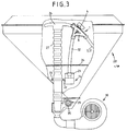
- FIG. 3 a schematic overall representation of a distributor head 26 is shown in FIG. 3, which is arranged together with its conveying material supply line 27 and its outgoing lines in a conveying material tank 28.
- the conveyed material is dosed from the conveyed material tank 28 via a metering device 29 and fed to the conveyed material supply line 27 via a blower 30, which leads to the distributor head 26.
- the connectors 1 already shown in FIG. 1 are arranged, which have the locking flap 4 already described.
- Lines 31 are arranged on the connecting pieces 1, which lead to the delivery members for the conveyed material and, in addition, return lines 32 are arranged on the connecting pieces 1, which feed the conveyed material deflected when the shut-off flap 4 is closed to the metering device 29.
- the return lines 32 are connected to the collector 14 shown in FIG. 2, the return lines 32 being fixed on one of the connections 15 to 20 of the collector 14.
- the connections not occupied by a return line 32 are closed by means of the plug 21.
- the returned conveyed material arrives directly via the return lines 6, 32 and via the collector 14 onto the metering device 29 and is then immediately fed back to the distributor.
- the collector 14 is to be seen as part of the return duct, since it forwards the derived conveyed material, and accordingly the collector 14 can also be provided with an exhaust air line 8. An obstruction of the metering device 29 by too much recirculated conveying air does not take place due to the exhaust air lines 8 used.
- the collector 14 Between the walls of the collector 14 and the tank walls there is a flow gap for material to be conveyed, through which the material to be conveyed passes from the tank 28 to the metering device 29.
- the flow of the material to be conveyed between the outer wall of the collector and the inner wall of the tank is more or less high. Therefore, it is advantageous to arrange the collector 14 so that it is adjustable. H. for example vertically adjustable, so that with a higher setting of the collector 14, the gap between the collector 14 and the inner wall of the tank is enlarged and the flow rate of the conveyed material is increased.
- the height adjustment of the collector 14 can, for. B. done in that a connection 22 of the collector 14 is connected to a fastening device, which in turn is variable in height.
- a fastening device In the fastening device, it can be, for. B. is a pipe clamp 33 which is attached to the riser pipe or the conveying material supply line 27 for the conveyed material in the direction of the distributor.
Landscapes
- Life Sciences & Earth Sciences (AREA)
- Soil Sciences (AREA)
- Environmental Sciences (AREA)
- Sowing (AREA)
- Air Transport Of Granular Materials (AREA)
Applications Claiming Priority (2)
| Application Number | Priority Date | Filing Date | Title |
|---|---|---|---|
| DE19613785 | 1996-04-04 | ||
| DE19613785A DE19613785C2 (de) | 1996-04-04 | 1996-04-04 | Abluftleitung für eine pneumatisch arbeitende Verteilmaschine |
Publications (3)
| Publication Number | Publication Date |
|---|---|
| EP0799560A2 true EP0799560A2 (fr) | 1997-10-08 |
| EP0799560A3 EP0799560A3 (fr) | 1999-03-17 |
| EP0799560B1 EP0799560B1 (fr) | 2000-11-15 |
Family
ID=7790646
Family Applications (1)
| Application Number | Title | Priority Date | Filing Date |
|---|---|---|---|
| EP97102933A Expired - Lifetime EP0799560B1 (fr) | 1996-04-04 | 1997-02-22 | Conduite pour l'air de sortie d'un distributeur pneumatique |
Country Status (3)
| Country | Link |
|---|---|
| EP (1) | EP0799560B1 (fr) |
| DE (2) | DE19613785C2 (fr) |
| DK (1) | DK0799560T3 (fr) |
Cited By (14)
| Publication number | Priority date | Publication date | Assignee | Title |
|---|---|---|---|---|
| EP2272314A3 (fr) * | 2009-06-29 | 2011-06-22 | Amazonen-Werke H. Dreyer GmbH & Co. KG | Semoir pneumatique, notamment semoir monograin |
| EP2462795A3 (fr) * | 2010-12-09 | 2012-07-25 | RAUCH Landmaschinenfabrik GmbH | Machine de distribution pneumatique |
| EP2695508A1 (fr) * | 2012-08-09 | 2014-02-12 | Alois Pöttinger Maschinenfabrik GmbH | Tête de répartition pour une machine à semence ou à engrais |
| US20170086353A1 (en) * | 2015-09-30 | 2017-03-30 | Deere & Company | Air seeding cart and manifold for same |
| WO2017055266A1 (fr) * | 2015-09-28 | 2017-04-06 | Horsch Maschinen Gmbh | Tour de distribution d'une machine de distribution agricole et procédé pour la mise hors circuit en série sur une telle tour de distribution |
| DE102016218531A1 (de) | 2016-09-27 | 2018-03-29 | Horsch Maschinen Gmbh | Verteilturm einer landwirtschaftlichen Verteilmaschine |
| CN108064500A (zh) * | 2016-11-10 | 2018-05-25 | 克韦尔内兰德公司 | 一种用于播种机的播种单元 |
| EP3372065A1 (fr) * | 2017-03-08 | 2018-09-12 | Horsch Maschinen GmbH | Tour de distribution d'une machine agricole, machine agricole et procédé de fonctionnement d'une telle machine agricole |
| WO2019030140A1 (fr) * | 2017-08-07 | 2019-02-14 | Amazonen-Werke H. Dreyer Gmbh & Co. Kg | Tête de distribution pour un distributeur à fonctionnement pneumatique |
| EP3501250A1 (fr) | 2017-12-23 | 2019-06-26 | Horsch Maschinen GmbH | Épandeur agricole et procédé de commande de rangée simple et groupée d'un tel épandeur agricole |
| EP3698614A1 (fr) * | 2019-02-25 | 2020-08-26 | Kverneland A/S | Dispositif pour une tour de distribution d'un engin agricole destiné à l'épandage à l'aide d'un flux de fluide d'un matériau granuleux, tour de distribution et engin agricole |
| WO2021204677A1 (fr) * | 2020-04-08 | 2021-10-14 | Amazonen-Werke H. Dreyer SE & Co. KG | Machine de distribution pneumatique |
| DE102021121313A1 (de) | 2021-08-17 | 2023-02-23 | Horsch Maschinen Gmbh | Verteilmaschine mit Verteilerturm und Absperreinrichtung |
| DE102022105720B3 (de) | 2022-03-11 | 2023-06-01 | Amazonen-Werke H. Dreyer SE & Co. KG | Verteilerkopf für eine landwirtschaftliche Ausbringmaschine und Ausbringmaschine zum Verteilen von Material |
Families Citing this family (18)
| Publication number | Priority date | Publication date | Assignee | Title |
|---|---|---|---|---|
| USD647542S1 (en) | 2009-09-11 | 2011-10-25 | Agco-Amity Jv, Llc | Seed brake |
| DE102013000758A1 (de) | 2013-01-16 | 2014-07-17 | Alois Pöttinger Maschinenfabrik Ges.m.b.H. | Verteilerkopf für eine Sä- und/oder Düngemaschine |
| DE102014108769A1 (de) | 2014-06-24 | 2015-12-24 | Amazonen-Werke H. Dreyer Gmbh & Co. Kg | Pneumatische Sämaschine |
| ITUB20152403A1 (it) | 2015-07-22 | 2017-01-22 | Matermacc S P A | Dispositivo di distribuzione di fertilizzanti. |
| DE102016115236A1 (de) * | 2016-08-17 | 2018-02-22 | Horsch Maschinen Gmbh | Verteilmaschine und Verfahren zur Aussaat von granulatartigem Verteilgut |
| DE102016010270A1 (de) | 2016-08-24 | 2018-03-01 | Gerald Funck | Verfahren und Vorrichtung zur Verteilung körnigen Guts auf mehrere Leitungen |
| WO2018046639A1 (fr) | 2016-09-09 | 2018-03-15 | Gerald Funck | Procédé et dispositif pour répartir un produit en grains sur un nombre variable de conduites |
| CA2977467C (fr) * | 2016-10-11 | 2026-01-13 | Deere & Company | Mecanisme de semoir |
| WO2018109157A1 (fr) | 2016-12-16 | 2018-06-21 | Gerald Funck | Procédé et dispositif pour dévier un écoulement comprenant un produit en grains sur différentes conduites et système ainsi équipé pour répartir du produit en grains sur un nombre variable de conduites |
| EA037483B1 (ru) | 2016-12-16 | 2021-04-01 | Геральд Функ | Способ и устройство для распределения сыпучего материала в переменное количество линий |
| DE102017203854A1 (de) | 2017-03-08 | 2018-09-13 | Horsch Maschinen Gmbh | Verteilerturm einer landwirtschaftlichen Maschine, landwirtschaftliche Maschine und Verfahren zum Betreiben einer solchen landwirtschaftlichen Maschine |
| DE102017113487A1 (de) | 2017-06-20 | 2018-12-20 | Amazonen-Werke H. Dreyer Gmbh & Co. Kg | Landwirtschaftliche pneumatische Verteilmaschine |
| DE102020129735A1 (de) | 2020-11-11 | 2022-05-12 | Amazonen-Werke H. Dreyer SE & Co. KG | Verteilvorrichtung für körniges Material |
| DE102020130985A1 (de) | 2020-11-24 | 2022-05-25 | Pöttinger Landtechnik Gmbh | Verteilerkopf für eine Sä- und/oder Düngemaschine |
| DE102021118521A1 (de) * | 2021-07-19 | 2023-01-19 | Amazonen-Werke H. Dreyer SE & Co. KG | Verteilvorrichtung für körniges Material |
| DE102021118523A1 (de) | 2021-07-19 | 2023-01-19 | Amazonen-Werke H. Dreyer SE & Co. KG | Verteilvorrichtung für körniges Material |
| DE102021127729A1 (de) | 2021-10-26 | 2023-04-27 | Amazonen-Werke H. Dreyer SE & Co. KG | Materialverteilsystem für eine landwirtschaftliche Ausbringmaschine |
| IT202300014499A1 (it) * | 2023-07-11 | 2025-01-11 | Maschio Gaspardo Spa | Macchina per la distribuzione pneumatica di materiali preferibilmente granulari |
Family Cites Families (4)
| Publication number | Priority date | Publication date | Assignee | Title |
|---|---|---|---|---|
| DE3622078A1 (de) * | 1986-07-02 | 1988-01-07 | Amazonen Werke Dreyer H | Pneumatische verteilmaschine |
| DE9313779U1 (de) * | 1993-09-11 | 1993-11-18 | Rabewerk Gmbh + Co, 49152 Bad Essen | Landwirtschaftliche pneumatische Verteilmaschine |
| DE9410912U1 (de) * | 1994-07-07 | 1994-09-29 | Accord-Landmaschinen Heinrich Weiste & Co GmbH, 59494 Soest | Verteiler für eine pneumatisch arbeitende Verteilmaschine für Saatgut, Dünger u.dgl. |
| DE19549577C3 (de) * | 1995-09-15 | 2003-12-11 | Amazonen Werke Dreyer H | Landwirtschaftliche Verteilmaschine |
-
1996
- 1996-04-04 DE DE19613785A patent/DE19613785C2/de not_active Expired - Fee Related
-
1997
- 1997-02-22 DK DK97102933T patent/DK0799560T3/da active
- 1997-02-22 DE DE59702624T patent/DE59702624D1/de not_active Expired - Lifetime
- 1997-02-22 EP EP97102933A patent/EP0799560B1/fr not_active Expired - Lifetime
Cited By (25)
| Publication number | Priority date | Publication date | Assignee | Title |
|---|---|---|---|---|
| EP2272314A3 (fr) * | 2009-06-29 | 2011-06-22 | Amazonen-Werke H. Dreyer GmbH & Co. KG | Semoir pneumatique, notamment semoir monograin |
| EP2462795A3 (fr) * | 2010-12-09 | 2012-07-25 | RAUCH Landmaschinenfabrik GmbH | Machine de distribution pneumatique |
| EP2695508A1 (fr) * | 2012-08-09 | 2014-02-12 | Alois Pöttinger Maschinenfabrik GmbH | Tête de répartition pour une machine à semence ou à engrais |
| EP3653036A1 (fr) * | 2015-09-28 | 2020-05-20 | Horsch Maschinen GmbH | Tête de distribution pour machine de distribution agricole et procédé de désactivation des rangs d'une telle tête de distribution |
| WO2017055266A1 (fr) * | 2015-09-28 | 2017-04-06 | Horsch Maschinen Gmbh | Tour de distribution d'une machine de distribution agricole et procédé pour la mise hors circuit en série sur une telle tour de distribution |
| CN108024500A (zh) * | 2015-09-28 | 2018-05-11 | 赫什机械有限公司 | 农业播撒机的播撒塔和用于断开这种播撒塔出口的方法 |
| CN108024500B (zh) * | 2015-09-28 | 2021-11-09 | 赫什机械有限公司 | 农业播撒机的播撒塔和用于断开这种播撒塔出口的方法 |
| US20170086353A1 (en) * | 2015-09-30 | 2017-03-30 | Deere & Company | Air seeding cart and manifold for same |
| US9648801B2 (en) * | 2015-09-30 | 2017-05-16 | Deere & Company | Air seeding cart and manifold for same |
| DE102016218531A1 (de) | 2016-09-27 | 2018-03-29 | Horsch Maschinen Gmbh | Verteilturm einer landwirtschaftlichen Verteilmaschine |
| CN108064500A (zh) * | 2016-11-10 | 2018-05-25 | 克韦尔内兰德公司 | 一种用于播种机的播种单元 |
| EP3372065A1 (fr) * | 2017-03-08 | 2018-09-12 | Horsch Maschinen GmbH | Tour de distribution d'une machine agricole, machine agricole et procédé de fonctionnement d'une telle machine agricole |
| EA038668B1 (ru) * | 2017-08-07 | 2021-10-01 | Амазонен-Верке Х. Дрейер Гмбх Энд Ко. Кг | Распределительная головка для пневматической разбрасывающей машины |
| WO2019030140A1 (fr) * | 2017-08-07 | 2019-02-14 | Amazonen-Werke H. Dreyer Gmbh & Co. Kg | Tête de distribution pour un distributeur à fonctionnement pneumatique |
| DE102017223789A1 (de) | 2017-12-23 | 2019-06-27 | Horsch Maschinen Gmbh | Landwirtschaftliche Verteilmaschine und Verfahren zur Einzelreihen- und Gruppenschaltung einer solchen landwirtschaftlichen Verteilmaschine |
| EP3501250A1 (fr) | 2017-12-23 | 2019-06-26 | Horsch Maschinen GmbH | Épandeur agricole et procédé de commande de rangée simple et groupée d'un tel épandeur agricole |
| EP3698614A1 (fr) * | 2019-02-25 | 2020-08-26 | Kverneland A/S | Dispositif pour une tour de distribution d'un engin agricole destiné à l'épandage à l'aide d'un flux de fluide d'un matériau granuleux, tour de distribution et engin agricole |
| WO2020173806A1 (fr) * | 2019-02-25 | 2020-09-03 | Kverneland A/S | Arrangement pour une tour de distribution d'une machine agricole servant à l'épandage assisté par un flux de fluide d'un matériau granulaire, tour de distribution et machine agricole |
| RU2770000C1 (ru) * | 2019-02-25 | 2022-04-14 | Квернеланд А/С | Устройство для распределительной башни сельскохозяйственной машины для осуществления поддерживаемого потоком текучей среды внесения гранулированного материала, распределительная башня и сельскохозяйственная машина |
| WO2021204677A1 (fr) * | 2020-04-08 | 2021-10-14 | Amazonen-Werke H. Dreyer SE & Co. KG | Machine de distribution pneumatique |
| EP4179859A1 (fr) * | 2020-04-08 | 2023-05-17 | Amazonen-Werke H. Dreyer SE & Co. KG | Machine de distribution pneumatique |
| US12193353B2 (en) | 2020-04-08 | 2025-01-14 | Amazonen-Werke H. Dreyer SE & Co. KG | Pneumatic distribution machine |
| DE102021121313A1 (de) | 2021-08-17 | 2023-02-23 | Horsch Maschinen Gmbh | Verteilmaschine mit Verteilerturm und Absperreinrichtung |
| DE102022105720B3 (de) | 2022-03-11 | 2023-06-01 | Amazonen-Werke H. Dreyer SE & Co. KG | Verteilerkopf für eine landwirtschaftliche Ausbringmaschine und Ausbringmaschine zum Verteilen von Material |
| EP4241548A1 (fr) * | 2022-03-11 | 2023-09-13 | Amazonen-Werke H. Dreyer SE & Co. KG | Tête de distribution pour une machine de distribution agricole et machine de distribution et procédé de distribution de matériau |
Also Published As
| Publication number | Publication date |
|---|---|
| DE59702624D1 (de) | 2000-12-21 |
| EP0799560A3 (fr) | 1999-03-17 |
| EP0799560B1 (fr) | 2000-11-15 |
| DE19613785C1 (de) | 1997-10-30 |
| DK0799560T3 (da) | 2001-02-05 |
| DE19613785C2 (de) | 2002-08-22 |
Similar Documents
| Publication | Publication Date | Title |
|---|---|---|
| DE19613785C2 (de) | Abluftleitung für eine pneumatisch arbeitende Verteilmaschine | |
| EP1003359B1 (fr) | Systeme de distribution d'un dispositif d'ensemencement | |
| EP0642729B1 (fr) | Distributeur pneumatique agricole | |
| EP2695508B1 (fr) | Tête de répartition pour une machine à semence ou à engrais | |
| DE102015116378A1 (de) | Verteilturm einer landwirtschaftlichen Verteilmaschine | |
| EP1164827A1 (fr) | Distributeur pneumatique | |
| DE4411240C2 (de) | Verteilerkopf für eine Verteilmaschine für Saatgut und/oder Dünger | |
| DE102010002200A1 (de) | Kalibriervorrichtung | |
| EP2462795A2 (fr) | Machine de distribution pneumatique | |
| EP3417688A1 (fr) | Machine d'épandage pneumatique agricole | |
| EP4072260A1 (fr) | Machine de distribution pneumatique | |
| EP3698614B1 (fr) | Dispositif pour une tour de distribution d'un engin agricole destiné à l'épandage à l'aide d'un flux de fluide d'un matériau granuleux, tour de distribution et engin agricole | |
| EP2805596B1 (fr) | Semoir | |
| EP2756744B1 (fr) | Tête de distribution pour un semoir ou un distributeur d'engrais | |
| DE19717214A1 (de) | Verteiler für pneumatische Drillmaschinen | |
| DE202004002923U1 (de) | Pneumatisch arbeitende Verteilmaschine | |
| DE3515362A1 (de) | Vorrichtung zum streuen von schuettfaehigem gut, insbesondere duenger | |
| DE202004002615U1 (de) | Pneumatisch arbeitende Verteilmaschine | |
| EP3917304B1 (fr) | Sas d'introduction de matière pour un épandeur et épandeur | |
| EP0391220A1 (fr) | Distributeur agricole | |
| DE102022108775A1 (de) | Landwirtschaftliche Verteilmaschine | |
| DE2238626C3 (de) | Maschine zum Ausbringen von gekörntem oder pulverförmigem Material | |
| DE2436355C3 (de) | Maschine zum Ausbringen von Saatgut und Düngemitteln | |
| DE102024129278A1 (de) | Landwirtschaftliche Feldspritze und Spritzvorrichtung für eine landwirtschaftliche Feldspritze | |
| DE8427678U1 (de) | Maschine zum pneumatischen Ausbringen von insbesondere körnigem Material |
Legal Events
| Date | Code | Title | Description |
|---|---|---|---|
| PUAI | Public reference made under article 153(3) epc to a published international application that has entered the european phase |
Free format text: ORIGINAL CODE: 0009012 |
|
| AK | Designated contracting states |
Kind code of ref document: A2 Designated state(s): DE DK FR GB NL SE |
|
| PUAL | Search report despatched |
Free format text: ORIGINAL CODE: 0009013 |
|
| AK | Designated contracting states |
Kind code of ref document: A3 Designated state(s): DE DK FR GB NL SE |
|
| 17P | Request for examination filed |
Effective date: 19990512 |
|
| 17Q | First examination report despatched |
Effective date: 19990909 |
|
| GRAG | Despatch of communication of intention to grant |
Free format text: ORIGINAL CODE: EPIDOS AGRA |
|
| GRAG | Despatch of communication of intention to grant |
Free format text: ORIGINAL CODE: EPIDOS AGRA |
|
| GRAH | Despatch of communication of intention to grant a patent |
Free format text: ORIGINAL CODE: EPIDOS IGRA |
|
| GRAH | Despatch of communication of intention to grant a patent |
Free format text: ORIGINAL CODE: EPIDOS IGRA |
|
| GRAA | (expected) grant |
Free format text: ORIGINAL CODE: 0009210 |
|
| AK | Designated contracting states |
Kind code of ref document: B1 Designated state(s): DE DK FR GB NL SE |
|
| REF | Corresponds to: |
Ref document number: 59702624 Country of ref document: DE Date of ref document: 20001221 |
|
| ET | Fr: translation filed | ||
| REG | Reference to a national code |
Ref country code: DK Ref legal event code: T3 |
|
| GBT | Gb: translation of ep patent filed (gb section 77(6)(a)/1977) |
Effective date: 20010213 |
|
| REG | Reference to a national code |
Ref country code: GB Ref legal event code: 746 Effective date: 20010312 |
|
| PLBE | No opposition filed within time limit |
Free format text: ORIGINAL CODE: 0009261 |
|
| STAA | Information on the status of an ep patent application or granted ep patent |
Free format text: STATUS: NO OPPOSITION FILED WITHIN TIME LIMIT |
|
| 26N | No opposition filed | ||
| REG | Reference to a national code |
Ref country code: GB Ref legal event code: IF02 |
|
| PGFP | Annual fee paid to national office [announced via postgrant information from national office to epo] |
Ref country code: NL Payment date: 20040216 Year of fee payment: 8 |
|
| PG25 | Lapsed in a contracting state [announced via postgrant information from national office to epo] |
Ref country code: NL Free format text: LAPSE BECAUSE OF NON-PAYMENT OF DUE FEES Effective date: 20050901 |
|
| NLV4 | Nl: lapsed or anulled due to non-payment of the annual fee |
Effective date: 20050901 |
|
| REG | Reference to a national code |
Ref country code: FR Ref legal event code: PLFP Year of fee payment: 20 |
|
| PGFP | Annual fee paid to national office [announced via postgrant information from national office to epo] |
Ref country code: DE Payment date: 20160218 Year of fee payment: 20 Ref country code: DK Payment date: 20160217 Year of fee payment: 20 |
|
| PGFP | Annual fee paid to national office [announced via postgrant information from national office to epo] |
Ref country code: SE Payment date: 20160217 Year of fee payment: 20 Ref country code: GB Payment date: 20160217 Year of fee payment: 20 Ref country code: FR Payment date: 20160218 Year of fee payment: 20 |
|
| REG | Reference to a national code |
Ref country code: DE Ref legal event code: R071 Ref document number: 59702624 Country of ref document: DE |
|
| REG | Reference to a national code |
Ref country code: DK Ref legal event code: EUP Effective date: 20170222 |
|
| REG | Reference to a national code |
Ref country code: GB Ref legal event code: PE20 Expiry date: 20170221 |
|
| REG | Reference to a national code |
Ref country code: SE Ref legal event code: EUG |
|
| PG25 | Lapsed in a contracting state [announced via postgrant information from national office to epo] |
Ref country code: GB Free format text: LAPSE BECAUSE OF EXPIRATION OF PROTECTION Effective date: 20170221 |