EP0799590A2 - Dispositif de présentation de marchandises - Google Patents
Dispositif de présentation de marchandises Download PDFInfo
- Publication number
- EP0799590A2 EP0799590A2 EP97100572A EP97100572A EP0799590A2 EP 0799590 A2 EP0799590 A2 EP 0799590A2 EP 97100572 A EP97100572 A EP 97100572A EP 97100572 A EP97100572 A EP 97100572A EP 0799590 A2 EP0799590 A2 EP 0799590A2
- Authority
- EP
- European Patent Office
- Prior art keywords
- magnetic
- magnetic body
- goods
- groove
- goods holder
- Prior art date
- Legal status (The legal status is an assumption and is not a legal conclusion. Google has not performed a legal analysis and makes no representation as to the accuracy of the status listed.)
- Withdrawn
Links
- 230000005291 magnetic effect Effects 0.000 claims abstract description 79
- 239000000463 material Substances 0.000 claims abstract description 14
- XEEYBQQBJWHFJM-UHFFFAOYSA-N Iron Chemical compound [Fe] XEEYBQQBJWHFJM-UHFFFAOYSA-N 0.000 claims abstract description 6
- 229910052742 iron Inorganic materials 0.000 claims abstract description 3
- 125000006850 spacer group Chemical group 0.000 claims description 7
- 238000000576 coating method Methods 0.000 claims description 2
- 239000011248 coating agent Substances 0.000 claims 1
- 230000002787 reinforcement Effects 0.000 abstract 1
- 230000000694 effects Effects 0.000 description 3
- 229910052782 aluminium Inorganic materials 0.000 description 2
- XAGFODPZIPBFFR-UHFFFAOYSA-N aluminium Chemical compound [Al] XAGFODPZIPBFFR-UHFFFAOYSA-N 0.000 description 2
- 229910052751 metal Inorganic materials 0.000 description 2
- 239000002184 metal Substances 0.000 description 2
- 239000011257 shell material Substances 0.000 description 2
- 238000004873 anchoring Methods 0.000 description 1
- 239000000969 carrier Substances 0.000 description 1
- 239000013536 elastomeric material Substances 0.000 description 1
- 230000003993 interaction Effects 0.000 description 1
- 238000002372 labelling Methods 0.000 description 1
- 230000014759 maintenance of location Effects 0.000 description 1
- 238000004519 manufacturing process Methods 0.000 description 1
- 239000000843 powder Substances 0.000 description 1
Images


Classifications
-
- A—HUMAN NECESSITIES
- A47—FURNITURE; DOMESTIC ARTICLES OR APPLIANCES; COFFEE MILLS; SPICE MILLS; SUCTION CLEANERS IN GENERAL
- A47F—SPECIAL FURNITURE, FITTINGS, OR ACCESSORIES FOR SHOPS, STOREHOUSES, BARS, RESTAURANTS OR THE LIKE; PAYING COUNTERS
- A47F5/00—Show stands, hangers, or shelves characterised by their constructional features
- A47F5/08—Show stands, hangers, or shelves characterised by their constructional features secured to the wall, ceiling, or the like; Wall-bracket display devices
-
- A—HUMAN NECESSITIES
- A47—FURNITURE; DOMESTIC ARTICLES OR APPLIANCES; COFFEE MILLS; SPICE MILLS; SUCTION CLEANERS IN GENERAL
- A47F—SPECIAL FURNITURE, FITTINGS, OR ACCESSORIES FOR SHOPS, STOREHOUSES, BARS, RESTAURANTS OR THE LIKE; PAYING COUNTERS
- A47F7/00—Show stands, hangers, or shelves, adapted for particular articles or materials
- A47F7/08—Show stands, hangers, or shelves, adapted for particular articles or materials for shoes
Definitions
- the invention is directed to a device of the type specified in the preamble of claim 1.
- the goods holder is held on the magnetic carrier by magnetic forces, which enables the goods containers to be attached and detached conveniently and quickly at various locations on the magnetic carrier.
- the invention has for its object an inexpensive device to develop the type specified in the preamble of claim 1, which allows a reliable magnetic attachment of the goods holder to the associated magnet carrier. This is achieved according to the invention by the measures specified in the characterizing part of claim 1, which have the following special meaning.
- the special groove profile of the wall surface which serves as a magnetic carrier in the invention, increases the magnetic force of the magnetic body located on the goods holder.
- the groove receives the magnetic body and surrounds it not only in the area of the groove base, but also on the groove flanks.
- the magnetic field lines emanating from three sides of the magnetic body are absorbed by the groove profile and thereby increase the magnetic interaction between the goods holder and the magnetic carrier. This significantly improves the security of the goods holder.
- the groove serves to mechanically guide the magnetic body recessed into it from the goods holder. Therefore, mechanical holding effects can also be added to the magnetic force if necessary.
- the device according to the invention has a profiled wall surface 10 as a magnetic carrier, the profile of which is divided into a plurality of parallel grooves 11. All the grooves 11 have a matching profile with the groove cross section 12 shown in FIG. 2.
- FIG. 2 also shows that the wall surface 10 is a profiled sheet 15, the grooves 11 of which already serve to reinforce it.
- the profiled sheet has a galvanized and / or colored powder-coated face 16 and back.
- the groove cross section 12 also has two mutually facing groove flanks 14.
- a goods holder 20 which in the present case consists of an L-shaped angled plate.
- the plate material cannot be magnetized and consists of aluminum. It goes without saying that any other non-magnetizable material could be used in addition to aluminum.
- the entire surface of the L-shaped plate is coated, which protects it from scratches. Due to its L-shape, the goods holder 20 is divided into a horizontal L-leg 21 which, such as. B. Fig. 7a shows, for the presentation of the goods 40, namely a shoe, is used.
- the other, vertical L-leg 22 of the goods holder 20 has at least one strip-shaped magnetic body 30 on its rear plate 23.
- the strip-shaped magnetic body 30 is fastened to the goods holder 20 by rivets 24.
- the front edge of the horizontal L-leg 21 can have an end strip 25 which again runs vertically and is a carrier of inscribable fields 26.
- the fields serve e.g. B. for price labeling of the presented goods.
- two magnetic bodies 30 are fastened to the goods holder 20, namely at a distance 17 which corresponds to the single or multiple distance 42 of the parallel grooves 11 in the profiled sheet 15.
- This groove spacing 42 is, as it were, the "positive" of the cross-sectional shape 12 of the groove 11 to be regarded as a profile negative.
- the profile of the sheet 15 can therefore also be characterized as a double Z profile.
- the strip-shaped magnetic body 30 has a strip cross-section 32 which essentially corresponds to that of the aforementioned groove cross-section 12. This has the following meaning for the intended use of the device.
- the wall surface 10 is part of a sales facility 28 or a sales rack 41, of which FIGS. 7a to 8b show examples.
- a goods holder 20 is attached to a selected location on this wall surface 10 simply by sunk its magnetic body 30 into freely selectable grooves 11. This results in a special magnetic effect between the wall surface 10 and the goods holder 20, because the magnetic fields emanating from the magnetic body 30 interact not only with the groove base 13, but also with the two lateral groove flanks 14 of the groove 11 used. This applies in particular if the aforementioned cross sections 32, 12 essentially match. A very large holding force is noticeable. If the cross-sectional shape is the same, the vertical leg 22 of the wall bracket 20 comes to lie flush on the end face 16 of the wall surface 10.
- the selected groove 11 is of course also used for mechanical guidance of the sunken magnetic body 30. It would also be possible to hold the magnetic body 30 mechanically, in addition to its magnetic effect, by tilting the two groove flanks 14. Surface structures or coatings, which are provided either on the groove 11 itself and / or on the magnetic body, could also be used for this purpose.
- the magnetic strip 30 in turn consists of several rod-shaped, individual magnetic elements 31, which are held together by a common sleeve made of rubber-like, elastomeric material.
- the magnetic elements 31 are divided by one Spacers 35 are held at a defined distance 18 from one another.
- this spacer 35 has a lattice-shaped structure and consists of a non-magnetizable material, namely plastic.
- the lattice structure of the spacer 35 comprises thin webs 34 and thicker bars 36. In some bars 36 there is a receptacle 37, which can be seen in FIG. 5, for a head of the previously described fastening rivet 24.
- the sleeve 33 not only encloses, as can be seen in FIG. 6 externally the magnetic body 30, but also fills with its material the spaces left free on the webs 34 and bars 36 of the spacer 35.
- Fig. 6 shows that the edge regions 37 of the magnetic strip 31 are not covered by the sheath 33, but are bare. As a result, these points 37 in the corner regions 19 of the groove cross section 12 shown in FIG. 2 can come into direct contact with the profiled sheet 15. Despite the free edge regions 37, the elastomeric sleeve reliably holds the magnetic elements 31 in the magnetic strip 30.
- a strip 38 also belongs to the strip-shaped magnetic body 30, on which the above-described magnetic elements 31 rest directly with their flat rear sides 39 according to FIG. 6 without the intermediate covering material 33.
- the disk 38 is made of magnetizable material, namely iron, and bundles, in the manner of an armature, the rear magnetic fields of the elements 31. This increases the magnetic effects on the front side 29 of the magnetic body 30, which can be seen in FIG. 5, where there is a thin layer of the elastomeric shell material 33.
- the shafts of the rivets 24 described are passed through this magnetizable disk 38. This improves the anchoring of the rivets 24 in the magnetic strip 30.
- the rivets 24 are integrated in the magnetic strip 30, which has the complex structure, shown in FIG.
- the magnetic strip 30 is fastened to the L-leg 22 with a strip 43 made of the same material as the plate of the wall holder 20, specifically by the rivet 24.
- the shafts of the rivet 24 also penetrate the strip 43 and the L-leg.
- the strip 43 serves to stiffen the magnetic strip 30 and the plate of the L-leg 22.
- FIG. 7a and 7b show the aforementioned sales facility 28 in the form of a closet, where two wall surfaces 10 with the numerous Grooves 11 having sheet metal profile 15 are provided in order to position a plurality of plate-shaped goods holders 20 at selectable locations.
- the position of the goods holder 20 can be changed quickly, their retention effect in the sales facility 28 being very great.
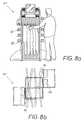
- FIG. 8a and 8b show a sales rack 41, where two grooved wall surfaces 10 are also provided for numerous holders 20, namely with a lateral offset to one another.
Landscapes
- Acyclic And Carbocyclic Compounds In Medicinal Compositions (AREA)
- Confectionery (AREA)
- Packaging For Recording Disks (AREA)
- Freezers Or Refrigerated Showcases (AREA)
Applications Claiming Priority (2)
| Application Number | Priority Date | Filing Date | Title |
|---|---|---|---|
| DE29606433U | 1996-04-06 | ||
| DE29606433U DE29606433U1 (de) | 1996-04-06 | 1996-04-06 | Verkaufsständer für Waren, insbesondere Schuhe |
Publications (2)
| Publication Number | Publication Date |
|---|---|
| EP0799590A2 true EP0799590A2 (fr) | 1997-10-08 |
| EP0799590A3 EP0799590A3 (fr) | 2000-12-13 |
Family
ID=8022313
Family Applications (1)
| Application Number | Title | Priority Date | Filing Date |
|---|---|---|---|
| EP97100572A Withdrawn EP0799590A3 (fr) | 1996-04-06 | 1997-01-16 | Dispositif de présentation de marchandises |
Country Status (3)
| Country | Link |
|---|---|
| EP (1) | EP0799590A3 (fr) |
| DE (1) | DE29606433U1 (fr) |
| PL (1) | PL319291A1 (fr) |
Cited By (2)
| Publication number | Priority date | Publication date | Assignee | Title |
|---|---|---|---|---|
| EP0956796A1 (fr) * | 1998-05-15 | 1999-11-17 | Volume Exquis (SARL) | Système de positionnement et de maintien d'objets sur une surface de base. |
| GB2422538A (en) * | 2005-01-31 | 2006-08-02 | Peter Catchpole | Clothing/footwear display stand which operates by magnetic attraction between the clothing/footwear and the stand |
Families Citing this family (3)
| Publication number | Priority date | Publication date | Assignee | Title |
|---|---|---|---|---|
| FR2905508A1 (fr) * | 2006-08-30 | 2008-03-07 | Daniel Rupin | Presentoir a bijoux |
| DE102010021741A1 (de) * | 2010-05-20 | 2011-11-24 | Octanorm-Vertriebs-GmbH für Bauelemente | Wandhalter für ein Magnetwandsystem |
| DE102010021740A1 (de) * | 2010-05-20 | 2011-11-24 | Octanorm-Vertriebs-GmbH für Bauelemente | Wandhalter für ein Magnetwandsystem |
Citations (1)
| Publication number | Priority date | Publication date | Assignee | Title |
|---|---|---|---|---|
| DE9207896U1 (de) | 1992-06-12 | 1992-09-03 | Markstahler + Barth GmbH + Co., 7500 Karlsruhe | Magnet-Träger für die Präsentation von Waren |
Family Cites Families (1)
| Publication number | Priority date | Publication date | Assignee | Title |
|---|---|---|---|---|
| SE9002942D0 (sv) * | 1990-09-14 | 1990-09-14 | Ahlberg & Co Ab | I ett stycke av plast format snaepplaasdon |
-
1996
- 1996-04-06 DE DE29606433U patent/DE29606433U1/de not_active Expired - Lifetime
-
1997
- 1997-01-16 EP EP97100572A patent/EP0799590A3/fr not_active Withdrawn
- 1997-04-04 PL PL31929197A patent/PL319291A1/xx unknown
Patent Citations (1)
| Publication number | Priority date | Publication date | Assignee | Title |
|---|---|---|---|---|
| DE9207896U1 (de) | 1992-06-12 | 1992-09-03 | Markstahler + Barth GmbH + Co., 7500 Karlsruhe | Magnet-Träger für die Präsentation von Waren |
Cited By (3)
| Publication number | Priority date | Publication date | Assignee | Title |
|---|---|---|---|---|
| EP0956796A1 (fr) * | 1998-05-15 | 1999-11-17 | Volume Exquis (SARL) | Système de positionnement et de maintien d'objets sur une surface de base. |
| FR2778541A1 (fr) * | 1998-05-15 | 1999-11-19 | Daniel Rupin | Systeme de positionnement et de maintien d'objets sur une surface de base |
| GB2422538A (en) * | 2005-01-31 | 2006-08-02 | Peter Catchpole | Clothing/footwear display stand which operates by magnetic attraction between the clothing/footwear and the stand |
Also Published As
| Publication number | Publication date |
|---|---|
| DE29606433U1 (de) | 1997-07-31 |
| PL319291A1 (en) | 1997-10-13 |
| EP0799590A3 (fr) | 2000-12-13 |
Similar Documents
| Publication | Publication Date | Title |
|---|---|---|
| DE3343066C2 (fr) | ||
| DE3705331A1 (de) | Montageeinheit fuer eine gedruckte schaltung | |
| DE3421505C2 (fr) | ||
| EP0799590A2 (fr) | Dispositif de présentation de marchandises | |
| DE202015106929U1 (de) | Beleuchtungsprofil und Regalbeleuchtung mit einem derartigen Beleuchtungsprofil | |
| EP1958305A1 (fr) | Dispositif de guidage d'un porte-conducteur | |
| DE3419660A1 (de) | Einkaufskorb | |
| DE8701868U1 (de) | Löschglied | |
| DE4334554C2 (de) | Kasten für elektrische Installationen | |
| EP1592026B1 (fr) | Aimant d'accrochage | |
| DE819705C (de) | Schild zur Phasenbezeichnung an Leitungsmasten | |
| DE2821256C2 (de) | Vorrichtung zur Preisauszeichnung in einem Verkaufskühlmöbel | |
| DE2623660C2 (de) | Vorrichtung zum Befestigen von parallelen Rohren auf einer Unterlage | |
| DE1298597B (de) | Tafel zur Halterung von Instrumenten | |
| DE2407076C3 (de) | Vorrichtung zur auswechselbaren Befestigung von Schildern mit einem ortsfest anzubringenden Halter und einem das Schild tragenden Gegenstück | |
| DE631774C (de) | Gehaeuse fuer Fensterbaskuele | |
| EP0598288A1 (fr) | Table de présentation pour carreaux | |
| DE7825983U1 (de) | Träger für Beschriftungselemente, insbesondere für den Ladenbau | |
| DE2123884A1 (de) | Anzeigetafel | |
| DE4242746A1 (de) | Tragplatte für Brücken und Rampen | |
| EP1580854A1 (fr) | Dispositif porte-étiquette pour armoire électrique | |
| DE7725258U1 (de) | Adapter für Kabelkanäle | |
| DE3039217C2 (de) | Vorrichtung zur Beschriftung von Informationsträgern | |
| DE29701715U1 (de) | Hinweisschild | |
| DE20105580U1 (de) | Lagerlift |
Legal Events
| Date | Code | Title | Description |
|---|---|---|---|
| PUAI | Public reference made under article 153(3) epc to a published international application that has entered the european phase |
Free format text: ORIGINAL CODE: 0009012 |
|
| AK | Designated contracting states |
Kind code of ref document: A2 Designated state(s): AT CH DE ES FR GB LI NL |
|
| PUAL | Search report despatched |
Free format text: ORIGINAL CODE: 0009013 |
|
| STAA | Information on the status of an ep patent application or granted ep patent |
Free format text: STATUS: THE APPLICATION HAS BEEN WITHDRAWN |
|
| AK | Designated contracting states |
Kind code of ref document: A3 Designated state(s): AT CH DE ES FR GB LI NL |
|
| 18W | Application withdrawn |
Withdrawal date: 20001125 |