EP0799676B1 - Poupée porte-pièces pour une rectifieuse avec déplacement linéaire automatique - Google Patents
Poupée porte-pièces pour une rectifieuse avec déplacement linéaire automatique Download PDFInfo
- Publication number
- EP0799676B1 EP0799676B1 EP19970500015 EP97500015A EP0799676B1 EP 0799676 B1 EP0799676 B1 EP 0799676B1 EP 19970500015 EP19970500015 EP 19970500015 EP 97500015 A EP97500015 A EP 97500015A EP 0799676 B1 EP0799676 B1 EP 0799676B1
- Authority
- EP
- European Patent Office
- Prior art keywords
- headstock
- slide
- run
- cylinder
- grinding machine
- Prior art date
- Legal status (The legal status is an assumption and is not a legal conclusion. Google has not performed a legal analysis and makes no representation as to the accuracy of the status listed.)
- Expired - Lifetime
Links
- 238000006073 displacement reaction Methods 0.000 title claims description 13
- 230000001105 regulatory effect Effects 0.000 claims description 10
- 230000008878 coupling Effects 0.000 claims description 4
- 238000010168 coupling process Methods 0.000 claims description 4
- 238000005859 coupling reaction Methods 0.000 claims description 4
- 238000005096 rolling process Methods 0.000 claims description 3
- 230000000452 restraining effect Effects 0.000 claims description 2
- 230000001276 controlling effect Effects 0.000 description 2
- 238000003754 machining Methods 0.000 description 2
- 235000015250 liver sausages Nutrition 0.000 description 1
- 238000005259 measurement Methods 0.000 description 1
- 230000003287 optical effect Effects 0.000 description 1
- 230000003252 repetitive effect Effects 0.000 description 1
- 238000006467 substitution reaction Methods 0.000 description 1
Images


Classifications
-
- B—PERFORMING OPERATIONS; TRANSPORTING
- B23—MACHINE TOOLS; METAL-WORKING NOT OTHERWISE PROVIDED FOR
- B23Q—DETAILS, COMPONENTS, OR ACCESSORIES FOR MACHINE TOOLS, e.g. ARRANGEMENTS FOR COPYING OR CONTROLLING; MACHINE TOOLS IN GENERAL CHARACTERISED BY THE CONSTRUCTION OF PARTICULAR DETAILS OR COMPONENTS; COMBINATIONS OR ASSOCIATIONS OF METAL-WORKING MACHINES, NOT DIRECTED TO A PARTICULAR RESULT
- B23Q1/00—Members which are comprised in the general build-up of a form of machine, particularly relatively large fixed members
- B23Q1/25—Movable or adjustable work or tool supports
- B23Q1/26—Movable or adjustable work or tool supports characterised by constructional features relating to the co-operation of relatively movable members; Means for preventing relative movement of such members
- B23Q1/28—Means for securing sliding members in any desired position
-
- B—PERFORMING OPERATIONS; TRANSPORTING
- B23—MACHINE TOOLS; METAL-WORKING NOT OTHERWISE PROVIDED FOR
- B23Q—DETAILS, COMPONENTS, OR ACCESSORIES FOR MACHINE TOOLS, e.g. ARRANGEMENTS FOR COPYING OR CONTROLLING; MACHINE TOOLS IN GENERAL CHARACTERISED BY THE CONSTRUCTION OF PARTICULAR DETAILS OR COMPONENTS; COMBINATIONS OR ASSOCIATIONS OF METAL-WORKING MACHINES, NOT DIRECTED TO A PARTICULAR RESULT
- B23Q1/00—Members which are comprised in the general build-up of a form of machine, particularly relatively large fixed members
- B23Q1/25—Movable or adjustable work or tool supports
- B23Q1/44—Movable or adjustable work or tool supports using particular mechanisms
- B23Q1/56—Movable or adjustable work or tool supports using particular mechanisms with sliding pairs only, the sliding pairs being the first two elements of the mechanism
- B23Q1/58—Movable or adjustable work or tool supports using particular mechanisms with sliding pairs only, the sliding pairs being the first two elements of the mechanism a single sliding pair
-
- B—PERFORMING OPERATIONS; TRANSPORTING
- B23—MACHINE TOOLS; METAL-WORKING NOT OTHERWISE PROVIDED FOR
- B23Q—DETAILS, COMPONENTS, OR ACCESSORIES FOR MACHINE TOOLS, e.g. ARRANGEMENTS FOR COPYING OR CONTROLLING; MACHINE TOOLS IN GENERAL CHARACTERISED BY THE CONSTRUCTION OF PARTICULAR DETAILS OR COMPONENTS; COMBINATIONS OR ASSOCIATIONS OF METAL-WORKING MACHINES, NOT DIRECTED TO A PARTICULAR RESULT
- B23Q16/00—Equipment for precise positioning of tool or work into particular locations not otherwise provided for
- B23Q16/001—Stops, cams, or holders therefor
-
- B—PERFORMING OPERATIONS; TRANSPORTING
- B24—GRINDING; POLISHING
- B24B—MACHINES, DEVICES, OR PROCESSES FOR GRINDING OR POLISHING; DRESSING OR CONDITIONING OF ABRADING SURFACES; FEEDING OF GRINDING, POLISHING, OR LAPPING AGENTS
- B24B41/00—Component parts such as frames, beds, carriages, headstocks
- B24B41/04—Headstocks; Working-spindles; Features relating thereto
-
- B—PERFORMING OPERATIONS; TRANSPORTING
- B24—GRINDING; POLISHING
- B24B—MACHINES, DEVICES, OR PROCESSES FOR GRINDING OR POLISHING; DRESSING OR CONDITIONING OF ABRADING SURFACES; FEEDING OF GRINDING, POLISHING, OR LAPPING AGENTS
- B24B5/00—Machines or devices designed for grinding surfaces of revolution on work, including those which also grind adjacent plane surfaces; Accessories therefor
- B24B5/36—Single-purpose machines or devices
- B24B5/42—Single-purpose machines or devices for grinding crankshafts or crankpins
Definitions
- the present invention relates to a grinding machine of horizontal rotating spindle with a headstock, as per the preamble of claim 1.
- An example of such a machine is disclosed by US 4 625 461 A.
- US-A-4625461 which represents the closest prior art, describes a grinding machine equipped with a CNC unit and having a headstock provided with an automatic linear displacement of variable run, where the grinding table is mobile in relation to the machine bed, and the headstock slides in relation to said table for spacing from the tailstock at a given measure according to the variable lenght of the workpiece, and both headstock and table have regulations means for their automatic relative displacement, which determine the different position of the headstock relative to the table and to the machine bed, provided with means for locking and realising the relative sliding between them automatically.
- the headstock slide runs along a guide-rail with a ball-bearing surface, fixed by screws to the grinder table.
- a position sensor generating an electrical signal is associated to a stop on the tail-stock to indicate any error in its movement in relation to a further stop which is movable.
- a headstock slide has its linear movement on guide-rails in the bed, with rollers bearing high loads and without play in the guides.
- Substitution of workpieces of different lengths in a single machining series means that the headstock must be moved, in controlled manner, over a long and variable run which, is obtained with a first device for regulating the variable run movement governed by the machine CNC where, in the first place, the headstock is secured to the grinder table and moves with it under the drive from the permanent motorised spindle on the machine bed, until the regulating device located at a reference point fixed on the bed stops the run.
- the second place with the headstock secured to the machine bed by the control element, the movement of the headstock in relation to the grinder table is released and now the table, carrying the tail-stock, slides under the control of the CNC to the distance programmed from the headstock.
- This second regulation device is located outside against the headstock housing.
- FIG. 1 is a face view of an embodiment of the headstock of a grinder with automatic linear movement, which is the object of the invention, showing the device for controlling the variable-length movement.
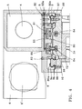
- FIG.2 is an elevation of the headstock in figure 1, showing the device for controlling the movement between two stops.
- FIG.3 is a transversal cross-section of the headstock along III-III in figure 1, showing the means for sliding the headstock in its automatic movement.
- FIG.4 is the transversal cross-section of the headstock in figure 3, showing the slide elements in detail.
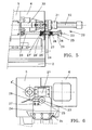
- FIGS. 5 and 6 are respectively elevation and profile views of the device for regulating the movement in figure 2.
- the grinding machine with a headstock 5,6,8 is shown which is the object of the invention, having a first device 13 for regulating its variable run displacements of a relatively large value, e.g. 100 mm, to obtain a measure 7 between the spindle support 4' and tail-stock support 3', such as that of a 300 mm crankshaft (not shown in drawings).
- a relatively large value e.g. 100 mm
- the headstock 5,6,8 with the horizontal drive spindle 4 slides on the grinder table 2, formed externally by the spindle housing 5 and the cabinet 6 housing the rotation servo-motor 6', both at the same height to form a single body supported by the headstock slide 8 which is coupled to two rolling units 9 as shown in figures 3 and 4, inserted on the headstock base plate 10, and the latter fixed to the grinder table 2 by the bolts 12.
- the grinder table 2 is mobile and has two longitudinal sectors 2 a and 2 b of differing profile, the first shown in figures 3 and 4 extending under the entire run of the headstock, while sector 2b of the table, shown in figure 6, of a known dovetail cross-section, extends to the rest of the table toward the tail-stock 3 end.
- the table 2 is driven by the grinder's internal continuous spindle 32 which is coupled to the table 2 by the shank nut 32', and driven by a servo-motor controlled by the grinder's CNC unit.
- the slide 8 and base pate 10 of the headstock are coupled as shown in figure 4 across a broken-profile coupling surface 80, where the running surfaces 80a are formed by the rolling units 9 extending right along the sector of the table 2 a , one on each side of the base plate 10, in the form of guide-rails 9 b joined by the lengthwise connecting flanges 88 and a number of commercial roller recirculation slides 9 a , aligned on each guide-rail 9 b and carrying the headstock slide 8, which is fixed to the roller recirculation slides 9 a by the bolts 82.
- the guide-rails 9a are secured to the headstock base-plate in parallel with the bolts 87.
- the headstock slide 8 has two pairs of hydraulic pistons 81 between the guide-rails 9 b , driven by a hydraulic circuit 83 with side input 83 a on the slide 8.
- the pistons 81 push the retaining bolts 84, whose square headstocks were restraining the slide 8 against the base plate 10 to stop it from sliding under the force of the disc springs 85.
- the distance between the coupled surfaces of the slide 8 and the base plate 10 when the slide is free to move is regulated by the shim 86 adjusting the bolt stop 84.
- the headstock displacements regulating device 13 shown in figures 1 and 3 comprises the positioning cylinder 15 whose support 15' is fastened to the machine bed 2' and whose rod 16 projects one shortened-cone retaining end 16', the microswitch 14 adjacent and connected to the cylinder 15, the support plate 19 forming part of the hood 5 with a housing 17 for said rod end 16', and a lug 18 belonging to the support plate 19 that presses the microswitch 14.
- the CNC is programmed for a movement of grinder table 2 according to the longitudinal shaft, equal to the difference of length between the new workpiece to be ground and the one it replaces.
- the headstock 1 is locked with the square-headstock bolts 84: with the headstock locked, the table 2 is moved in one direction until the microswitch 14 is operated and the headstock is held against the machine bed 2' by the rod 16. This is the headstock reference position for measurement of the length of movement.
- the movement of the slide 8 is released from the headstock by means of the pistons 81, and the table 2 with the tail-stock 3 moves a distance equalling the difference between the parts' lengths, while the headstock is restrained against the machine bed 2'.
- the regulating device 20 extends horizontally over the surface of the housing 5 opposite the support 3' for the workpiece, and consists of the cylinder 21 to drive the headstock 1 which is attached to the table 2 by a support plate 24, the piston 22 of the cylinder 21, the tie 23 which is movable with the piston 22, and parallel to it, and which crosses said support 24 and has two mobile stops 25 and 25' each of which is located on one side of the support 24, at an adjustable distance between them to define the repeated run of the headstock.
- the piston 22 for thrust on the headstock is connected to its housing 5 by a coupling element 30.
- Each mobile stop 25, 25' ends its run at the associated stops 27 and 27' secured to the support 24, and the two optical position sensors 26 associated with the fixed stops 27, 27' control the operation of the cylinder 21 to guarantee the correct length of movement.
- the tie 23 is made with a 10 mm diameter bar, for example, and the mobile stops 25 and 25' with a plate coaxial to the tie 23: a concave-convex washer 28 is secured against said plate with an elastic rubber washer 29 to dampen the impact against the fixed stops 27, 27'.
Landscapes
- Engineering & Computer Science (AREA)
- Mechanical Engineering (AREA)
- Constituent Portions Of Griding Lathes, Driving, Sensing And Control (AREA)
- Grinding Of Cylindrical And Plane Surfaces (AREA)
- Finish Polishing, Edge Sharpening, And Grinding By Specific Grinding Devices (AREA)
Claims (3)
- Rectifieuse à broche (4) à axe horizontal équipée d'une unité CNC, et dotée d'une poupée (5, 6) à déplacement linéaire pour la rectification des surfaces extérieures de pièces de diverses longueurs, où la table (2) de la rectifieuse est mobile par rapport au banc (2') de la machine et la poupée est coulissante par rapport à la table (2) au moyen d'un chariot (8) porte-poupée sur glissières doté d'unités de roulement (9), pour être placée à une mesure (7) déterminée en fonction de la longueur variable de la pièce, et toutes deux, la poupée (5,6) et la table (2), disposent de moyens de réglage (13, 20, 21, 31, 32) pour leur déplacement relatif automatique, caractérisé en ce que le déplacement automatique est variable et répété sur les deux courses par moyen de deux dispositifs (13, 20) pour le réglage automatique de chaque course, qui déterminera les différentes positions de la poupée par rapport à la table (2) et au banc (2') de la machine, le premier dispositif (13) comprenant un accouplement (8, 9, 10) à roulement entre le chariot (8) porte-poupée et la table (2) pourvu de moyens (81, 83, 84, 85) automatiques de blocage et de dégagement automatique du glissement de la poupée, et le second dispositif (20) réglant la course répétée comprend un cylindre (21) d'impulsion de la poupée (5,6) fixé à la table (2), une entretoise (23) parallèle au cylindre (21) et entraínée par le piston (22), deux butées mobiles (25, 25') sur cette entretoise (23) distantes entre elles en fonction de la longueur de la course, deux butées (27, 27') fixes sur la table (2) et deux capteurs (26, 26') associés à ces butées fixes (7, 27').
- La rectifieuse de la revendication 1, où l'accouplement (6,9,10) entre le chariot (8) porte-poupée et la table (2) comprend un circuit hydraulique (83) interne, une semelle (10) de poupée fixée à la table (2), deux unités de roulement (9) interposées entre le chariot (8) et la semelle (10), deux pistons (81) logés dans le chariot (8) et actionnés par ce circuit hydraulique (8), lesquels pour dégager le glissement tirent sur une vis (84) de blocage à tête carrée qui soutient la semelle (10) contre le chariot (8) sous la force d'un ressort (85).
- La rectifieuse de la revendication 1, où le dispositif (13) de réglage du déplacement à course variable comprend un cylindre (15) de positionnement de la poupée (5,6) par rapport à un point de référence du banc (2'9, une tige (16) de retenue de la poupée contre le banc (2') et un microrupteur (14) fixé à ce cylindre (159, qui commande la tige (16) de retenue après le déplacement initial de la table (2) et de la poupée.
Applications Claiming Priority (2)
| Application Number | Priority Date | Filing Date | Title |
|---|---|---|---|
| ES9600789 | 1996-04-02 | ||
| ES9600789A ES2141637B1 (es) | 1996-04-02 | 1996-04-02 | Cabezal pieza con desplazamiento lineal automatico para una rectificadora. |
Publications (2)
| Publication Number | Publication Date |
|---|---|
| EP0799676A1 EP0799676A1 (fr) | 1997-10-08 |
| EP0799676B1 true EP0799676B1 (fr) | 2001-04-11 |
Family
ID=8294409
Family Applications (1)
| Application Number | Title | Priority Date | Filing Date |
|---|---|---|---|
| EP19970500015 Expired - Lifetime EP0799676B1 (fr) | 1996-04-02 | 1997-01-22 | Poupée porte-pièces pour une rectifieuse avec déplacement linéaire automatique |
Country Status (3)
| Country | Link |
|---|---|
| EP (1) | EP0799676B1 (fr) |
| DE (1) | DE69704512T2 (fr) |
| ES (1) | ES2141637B1 (fr) |
Families Citing this family (2)
| Publication number | Priority date | Publication date | Assignee | Title |
|---|---|---|---|---|
| CA2335626A1 (fr) * | 1998-06-25 | 1999-12-29 | Unova U.K. Limited | Appareil et procede de rectification de pieces composites |
| CN116511925A (zh) * | 2023-06-05 | 2023-08-01 | 樟树市兴隆高新材料有限公司 | 一种模具钢高精度磨铣装置 |
Family Cites Families (5)
| Publication number | Priority date | Publication date | Assignee | Title |
|---|---|---|---|---|
| US3763600A (en) * | 1972-04-21 | 1973-10-09 | Landis Tool Co | Carriage positioning device for a grinding machine |
| CH666215A5 (de) * | 1984-01-13 | 1988-07-15 | Schaudt Maschinenbau Gmbh | Verfahren zum einstellen der laengsposition einer werkstueckstuetzeinheit oder eines aehnlichen maschinenelementes einer rundschleifmaschine. |
| DE3524438C2 (de) * | 1985-07-09 | 1994-01-27 | Schaudt Maschinenbau Gmbh | Einrichtung zur Zylinderfehlerkompensation an einer Schleifmaschine |
| DE3734720A1 (de) | 1987-10-14 | 1989-04-27 | Chiron Werke Gmbh | Werkzeugmaschine |
| SE463447B (sv) * | 1989-04-19 | 1990-11-26 | Uva Ab | Saett vid datorstyrd omstaellning av slipmaskin samt datorstyrd slipmaskin, skaerskilt rundslipmaskin |
-
1996
- 1996-04-02 ES ES9600789A patent/ES2141637B1/es not_active Expired - Fee Related
-
1997
- 1997-01-22 DE DE1997604512 patent/DE69704512T2/de not_active Expired - Fee Related
- 1997-01-22 EP EP19970500015 patent/EP0799676B1/fr not_active Expired - Lifetime
Also Published As
| Publication number | Publication date |
|---|---|
| DE69704512T2 (de) | 2001-09-27 |
| ES2141637B1 (es) | 2000-11-01 |
| ES2141637A1 (es) | 2000-03-16 |
| DE69704512D1 (de) | 2001-05-17 |
| EP0799676A1 (fr) | 1997-10-08 |
Similar Documents
| Publication | Publication Date | Title |
|---|---|---|
| US5115901A (en) | Automatic adjustment of pallet workpiece support members | |
| US4766703A (en) | Adjustable support rest for a cylinder grinding machines or the like | |
| US5346058A (en) | Automatic adjustment of pallet workpiece support members | |
| EP0167659B1 (fr) | Dispositif pour le roulage de chantournement des tourillons et des manetons | |
| SK39995A3 (en) | Grinding machine utilizing multiple, parallel, abrasive belts for simultaneously grinding surfaces on a workpiece | |
| US5060780A (en) | Pallets for supporting workpieces and automatic adjustment of pallet workpiece support members | |
| US4607461A (en) | Accurate positioning apparatus | |
| US3097568A (en) | Machine tool | |
| SK39895A3 (en) | Locking mechanism for multiple belt grinding machine | |
| US5251404A (en) | Belt grinder for crankshaft pins | |
| EP0799676A1 (fr) | Poupée porte-pièces pour une rectifieuse avec déplacement linéaire automatique | |
| JPS61188050A (ja) | 機械加工中の自動誤差補正装置 | |
| US5249394A (en) | Chuck indexing method | |
| US4170159A (en) | Linear positioning apparatus | |
| US5255778A (en) | Automatic adjustment of pallet workpiece support members | |
| JP3012691B2 (ja) | 板の縁を選択的に成形する方法および装置 | |
| US3233521A (en) | Rail leveling device | |
| US5099978A (en) | Automatic adjustment of pallet workpiece support members | |
| DE3721573A1 (de) | Schleifscheiben-positionsabtasteinrichtung | |
| US4190390A (en) | Apparatus for machining critical surfaces of railroad truck side frames | |
| US4729232A (en) | Machines for pressure forming surface configurations on a rotary workpiece | |
| US4524545A (en) | Grinding machine | |
| NL8901027A (nl) | Inrichting voor het tweezijdig kopslijpen van snijfrezen. | |
| US3138998A (en) | Surface finishing apparatus | |
| SU1077767A2 (ru) | Механизм подачи шлифовальной бабки |
Legal Events
| Date | Code | Title | Description |
|---|---|---|---|
| PUAI | Public reference made under article 153(3) epc to a published international application that has entered the european phase |
Free format text: ORIGINAL CODE: 0009012 |
|
| AK | Designated contracting states |
Kind code of ref document: A1 Designated state(s): DE FR GB IT |
|
| 17P | Request for examination filed |
Effective date: 19980218 |
|
| 17Q | First examination report despatched |
Effective date: 19990813 |
|
| GRAG | Despatch of communication of intention to grant |
Free format text: ORIGINAL CODE: EPIDOS AGRA |
|
| GRAG | Despatch of communication of intention to grant |
Free format text: ORIGINAL CODE: EPIDOS AGRA |
|
| GRAH | Despatch of communication of intention to grant a patent |
Free format text: ORIGINAL CODE: EPIDOS IGRA |
|
| GRAH | Despatch of communication of intention to grant a patent |
Free format text: ORIGINAL CODE: EPIDOS IGRA |
|
| GRAA | (expected) grant |
Free format text: ORIGINAL CODE: 0009210 |
|
| AK | Designated contracting states |
Kind code of ref document: B1 Designated state(s): DE FR GB IT |
|
| ITF | It: translation for a ep patent filed | ||
| REF | Corresponds to: |
Ref document number: 69704512 Country of ref document: DE Date of ref document: 20010517 |
|
| ET | Fr: translation filed | ||
| REG | Reference to a national code |
Ref country code: GB Ref legal event code: IF02 |
|
| PLBE | No opposition filed within time limit |
Free format text: ORIGINAL CODE: 0009261 |
|
| STAA | Information on the status of an ep patent application or granted ep patent |
Free format text: STATUS: NO OPPOSITION FILED WITHIN TIME LIMIT |
|
| 26N | No opposition filed | ||
| PGFP | Annual fee paid to national office [announced via postgrant information from national office to epo] |
Ref country code: GB Payment date: 20040116 Year of fee payment: 8 |
|
| PGFP | Annual fee paid to national office [announced via postgrant information from national office to epo] |
Ref country code: FR Payment date: 20040129 Year of fee payment: 8 |
|
| PGFP | Annual fee paid to national office [announced via postgrant information from national office to epo] |
Ref country code: DE Payment date: 20040220 Year of fee payment: 8 |
|
| PG25 | Lapsed in a contracting state [announced via postgrant information from national office to epo] |
Ref country code: IT Free format text: LAPSE BECAUSE OF NON-PAYMENT OF DUE FEES;WARNING: LAPSES OF ITALIAN PATENTS WITH EFFECTIVE DATE BEFORE 2007 MAY HAVE OCCURRED AT ANY TIME BEFORE 2007. THE CORRECT EFFECTIVE DATE MAY BE DIFFERENT FROM THE ONE RECORDED. Effective date: 20050122 Ref country code: GB Free format text: LAPSE BECAUSE OF NON-PAYMENT OF DUE FEES Effective date: 20050122 |
|
| PG25 | Lapsed in a contracting state [announced via postgrant information from national office to epo] |
Ref country code: DE Free format text: LAPSE BECAUSE OF NON-PAYMENT OF DUE FEES Effective date: 20050802 |
|
| GBPC | Gb: european patent ceased through non-payment of renewal fee |
Effective date: 20050122 |
|
| PG25 | Lapsed in a contracting state [announced via postgrant information from national office to epo] |
Ref country code: FR Free format text: LAPSE BECAUSE OF NON-PAYMENT OF DUE FEES Effective date: 20050930 |
|
| REG | Reference to a national code |
Ref country code: FR Ref legal event code: ST |