EP0799691A2 - Presse isostatique - Google Patents
Presse isostatique Download PDFInfo
- Publication number
- EP0799691A2 EP0799691A2 EP97103570A EP97103570A EP0799691A2 EP 0799691 A2 EP0799691 A2 EP 0799691A2 EP 97103570 A EP97103570 A EP 97103570A EP 97103570 A EP97103570 A EP 97103570A EP 0799691 A2 EP0799691 A2 EP 0799691A2
- Authority
- EP
- European Patent Office
- Prior art keywords
- press
- tool
- frame
- connecting plates
- guide
- Prior art date
- Legal status (The legal status is an assumption and is not a legal conclusion. Google has not performed a legal analysis and makes no representation as to the accuracy of the status listed.)
- Ceased
Links
- 230000007246 mechanism Effects 0.000 claims abstract description 16
- 238000004519 manufacturing process Methods 0.000 claims abstract description 5
- 238000000465 moulding Methods 0.000 claims abstract description 3
- 125000006850 spacer group Chemical group 0.000 claims description 9
- 229910010293 ceramic material Inorganic materials 0.000 claims description 2
- 239000000463 material Substances 0.000 abstract description 3
- 238000003825 pressing Methods 0.000 description 8
- 238000010276 construction Methods 0.000 description 4
- 230000006978 adaptation Effects 0.000 description 3
- 238000000034 method Methods 0.000 description 3
- 230000008569 process Effects 0.000 description 3
- 239000000919 ceramic Substances 0.000 description 2
- 238000006243 chemical reaction Methods 0.000 description 2
- 238000005516 engineering process Methods 0.000 description 2
- 238000000462 isostatic pressing Methods 0.000 description 2
- 230000036316 preload Effects 0.000 description 2
- 230000009467 reduction Effects 0.000 description 2
- 238000010521 absorption reaction Methods 0.000 description 1
- 230000008901 benefit Effects 0.000 description 1
- 230000008859 change Effects 0.000 description 1
- 238000011161 development Methods 0.000 description 1
- 230000018109 developmental process Effects 0.000 description 1
- 239000008187 granular material Substances 0.000 description 1
- 230000002706 hydrostatic effect Effects 0.000 description 1
- 239000012528 membrane Substances 0.000 description 1
- 238000009420 retrofitting Methods 0.000 description 1
Images




Classifications
-
- B—PERFORMING OPERATIONS; TRANSPORTING
- B30—PRESSES
- B30B—PRESSES IN GENERAL
- B30B15/00—Details of, or accessories for, presses; Auxiliary measures in connection with pressing
- B30B15/04—Frames; Guides
-
- B—PERFORMING OPERATIONS; TRANSPORTING
- B30—PRESSES
- B30B—PRESSES IN GENERAL
- B30B11/00—Presses specially adapted for forming shaped articles from material in particulate or plastic state, e.g. briquetting presses, tabletting presses
- B30B11/001—Presses specially adapted for forming shaped articles from material in particulate or plastic state, e.g. briquetting presses, tabletting presses using a flexible element, e.g. diaphragm, urged by fluid pressure; Isostatic presses
- B30B11/002—Isostatic press chambers; Press stands therefor
Definitions
- the invention relates to an isostatic press for compacting powdery or granulated material, in particular ceramic material, according to the preamble of patent claim 1.
- the pulverulent material is compressed under hydrostatic pressure within a tool which is firmly positioned in a press frame above a tool plate.
- the closing force is usually applied via a hydraulic working cylinder, with which a guide cross-piece carrying a tool part or a tool part itself is moved on and against the tool.
- the working cylinder executes a stroke after ejecting the previously produced molded article in order to bring the guide cross-member into the closed position, after which the actual closing force for compressing the ceramic molded part is again via the Working cylinder is applied.
- the object of the invention is to provide an isostatic press which can be adapted to different applications in the manner of a modular system, but the press should nevertheless be of robust and simple construction.
- the invention is characterized by a two-stage drive device for the movable tool parts on the guide crossmember, a rapid movement of the guide crossmember being effected by a crank mechanism and the closing force being applied by a short-stroke cylinder which is arranged at the free end of the locking lever of the crank mechanism and directly on the guide cross acts.
- This short-stroke cylinder can also carry out additional tool movements, for example, the expansion of the press frame and the axial deflection of the pressed part in the case of isostatic To compensate for pressure reduction (pull-off movement). Since the pressing force is applied via the preload cylinder in the extended position of the crank drive, the crank drive can be dimensioned simply because the force is in the ideal position, i.e.
- the simple crank drive means that the space required for this unit within the press can be reduced, which in turn affects the design of the press frame.
- the press frame can be constructed from longitudinal bars designed as hollow profiles, which are connected by simple spacers, so that there is a stable press frame structure which is easy to assemble and disassemble due to the use of the screw connections. This allows a modular system to be implemented in conjunction with the specially selected drive device, which makes it possible, for example, to build a press for laboratory use with a single tool with a minimal degree of automation up to series production with multiple tools and a maximum degree of automation.
- an essential feature is that the same pressing technology is used in all stages of construction and expansion. This means that the user can transfer the data and knowledge developed on a laboratory scale to series production without changing the pressing technology. This possibility of expanding from the laboratory press to the production press is of great advantage, with all interfaces being prepared for the expansion on the press.
- the modular system manages with a few modular basic elements that can always be used when changing the press. When changing the press, for example, identical connecting plates, tool traverses, spacers and screw connections can be used and it is only necessary to replace the longitudinal spars adapted to a certain stroke with longer or shorter longitudinal spars. This enables universal conversion to a wide variety of applications, taking into account the customer's basic concept.
- an isostatic press can thus be built up for different pressing processes, for example for the pressing processes “lifting out”, “lifting out” with “filling around the mandrel”, “ejecting”, “ejecting” with “filling around the mandrel”, “ Lowering “,” Lowering “with” filling around the mandrel “and, for example,” swivel crossbar ", in which the tool crossbar is pivotally arranged so that the tool can be pivoted relative to the guide crossmember per work cycle.
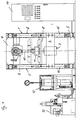
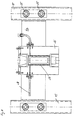
- Fig. 1 shows a schematic representation of a press for the isostatic pressing of moldings made of ceramic powdery material, which comprises a press frame, generally designated 1, here in a vertical construction, which consists of two side frame halves 2 and 3, which at their upper and lower End connected by connecting plates 4 and 5.
- a tool traverse 6 is fixed, in which the tool 7 is suspended and thus fastened.
- a drive device for moving a guide crossmember 8 guided on the press frame 1 is arranged, the drive device having a mechanical locking device, preferably in the form of a mechanical articulated drive, which in the preferred embodiment is designed as a crank drive 9, on its connecting rod-type locking lever 10, a hydraulic preload cylinder designed as a short-stroke cylinder 11 is arranged.
- the short-stroke cylinder 11 is arranged between the crank mechanism 9 and the guide crossmember 8 and thus acts directly on the guide crossmember 8.
- FIG. 1 also shows a laterally arranged isostatic pressing device 12 and a hydraulic unit 13 and, to the right of the press, a control cabinet 14 for the press, a detailed description of which can be dispensed with here.
- FIG. 1 shows an embodiment with only one mechanical locking device with a hydraulic pretensioning cylinder arranged above the tool 7, in which embodiment the crank mechanism has a stroke of 350 mm, for example.
- Fig. 1 is also shown with a dash-dotted line, the retracted, i.e. lifted off the tool 7 position of the guide cross member representing or receiving the upper tool upper part, the position of the guide cross bar 8 in a fully drawn line showing the downward position, the actual closing force is generated by the extension stroke of the short-stroke cylinder and also the locking in the pressing position.
- the short-stroke cylinder can also compensate for the expansion of the press frame and the axial deflection of the pressed part during isostatic pressure reduction (forcing movement).
- crank mechanism is only applied by pretensioning and pressing force in the extended position of the lever 10, so that a good force absorption is ensured via the mechanical locking device. It should only be mentioned in passing that the crank drive is driven by means of a frequency-controlled worm gear motor.
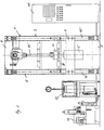
- the embodiment according to FIG. 2 differs from the press according to FIG. 1 only in the longer stroke of the crank mechanism 9, the height of the press frame being greater in adaptation to the larger stroke of the crank mechanism, here a stroke of 600 mm.
- This can be done by simply retrofitting the press by replacing the shorter bars 15 of FIG. 1 with longer bars 15 ', the other components of the press apart from the longer locking lever 10' being the same components as in the press of FIG. 1 and to that extent are also provided with the same reference numerals.
- Only the tool accommodated in the tool traverse 6 is of different types and is therefore designated by 7 '.
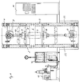
- the press is additionally equipped with a lower crank mechanism 16 arranged between the connecting plates 5, the closing lever 17 of which acts on a guide cross member 19 via a downstream short-stroke cylinder 18 in order to move the lower tool parts.
- 3 is constructed analogously to the press according to FIG. 1, but has, in adaptation to the two mechanical locking devices and the two short-stroke cylinders 11 and 18, longer bars 20, although here too the other basic press elements can be used in a modular manner.
- crank drives 9 and 16 are arranged on both sides of the tool traverse 6 receiving the tool 7, the lower crank drive 16 being characterized by a larger stroke length of, for example, 600 mm, with a stroke of 350 mm of the upper crank mechanism 9 differs.
- the structure is again identical, with the exception of the spars 22 of the press frame 1, which are longer due to the additional lower crank mechanism 21 including the short-stroke cylinder 18.
- FIGS. 1 to 4 show very clearly the modular principle of the press according to the invention, in which only in adaptation to a different number of crank drives with one-sided or two-sided arrangement with respect to the tool traverse and / or a longer working stroke accordingly longer bars of the press frame are used, but the rest of the components can still be used.
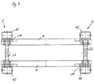
- FIG. 7 shows that the press frame 1 is constructed approximately in the construction of FIG. 1 from four longitudinal spars 15, two of which are connected in pairs by simple spacers 23 to the two side frame halves 2 and 3 (see Fig. 6). The two side frame halves 2 and 3 are finally connected to one another at the upper and lower end region of the bars 15 by connecting plates 4 and 5, respectively.
- Fig. 5 shows that the upper and lower connecting plates 4 and 5 at the upper and lower ends of the corresponding spar 15 are arranged. As can be seen from FIG.
- two connecting plates 4 and 5 are arranged in the upper end area and in the lower end area, between which the crank mechanism is suspended in each case by screw connections.
- the spacers 23, as can best be seen from FIG. 6, are arranged just below or just above the corresponding connecting plates 4 and 5.
- both the connecting plates 4 and 5 and the spacers 23 are connected via screw connections to the spars 15 and expediently via welded flanges 24 and 25. Because of these screw connections between the connecting plates, the spacers and the Holmen offers a quick change opportunity in the sense of the desired modular system.
- FIGS. 8 and 9 show the tool traverse, which in turn is composed of two connecting plates 6a and 6b arranged opposite one another, which are connected to the bars 15 by means of fastening screw bolts.
- the tool 7 is accommodated between the connecting plates 6a and 6b of the tool traverse 6, again by screwing and / or pinning.
- the tool traverse 6 is in this case firmly positioned with respect to the bars 15 via the fastening bolts 26.
- FIG. 8 finally shows a side view of the tool with tool block 26 and isostatic membrane 27 and the pressure medium supply 28 to the tool.
Landscapes
- Engineering & Computer Science (AREA)
- Mechanical Engineering (AREA)
- Physics & Mathematics (AREA)
- Fluid Mechanics (AREA)
- Press Drives And Press Lines (AREA)
- Press-Shaping Or Shaping Using Conveyers (AREA)
- Presses And Accessory Devices Thereof (AREA)
Applications Claiming Priority (2)
| Application Number | Priority Date | Filing Date | Title |
|---|---|---|---|
| DE19613047 | 1996-04-01 | ||
| DE1996113047 DE19613047A1 (de) | 1996-04-01 | 1996-04-01 | Isostatische Presse |
Publications (2)
| Publication Number | Publication Date |
|---|---|
| EP0799691A2 true EP0799691A2 (fr) | 1997-10-08 |
| EP0799691A3 EP0799691A3 (fr) | 1997-10-15 |
Family
ID=7790187
Family Applications (1)
| Application Number | Title | Priority Date | Filing Date |
|---|---|---|---|
| EP97103570A Ceased EP0799691A3 (fr) | 1996-04-01 | 1997-03-04 | Presse isostatique |
Country Status (3)
| Country | Link |
|---|---|
| EP (1) | EP0799691A3 (fr) |
| JP (1) | JPH106090A (fr) |
| DE (1) | DE19613047A1 (fr) |
Cited By (1)
| Publication number | Priority date | Publication date | Assignee | Title |
|---|---|---|---|---|
| WO2004085878A1 (fr) * | 2003-03-24 | 2004-10-07 | Evgenny Alexeevich Don | Mecanisme de force axoide equilibre et presse axoide |
Families Citing this family (6)
| Publication number | Priority date | Publication date | Assignee | Title |
|---|---|---|---|---|
| DE19846541A1 (de) * | 1998-10-09 | 2000-04-13 | Thyssen Krupp Ag | Rahmen für eine Reifenheizpresse |
| JP5026117B2 (ja) * | 2007-03-15 | 2012-09-12 | 住友重機械テクノフォート株式会社 | プレスフレーム |
| JP5026116B2 (ja) * | 2007-03-15 | 2012-09-12 | 住友重機械テクノフォート株式会社 | プレスフレーム |
| CN104416105A (zh) * | 2013-09-06 | 2015-03-18 | 天津市天锻压力机有限公司 | 具有四角调平功能的重型等温锻造压机 |
| CN104416102A (zh) * | 2013-09-06 | 2015-03-18 | 天津市天锻压力机有限公司 | 重型铝合金等温锻造液压机 |
| CN104842579A (zh) * | 2015-05-12 | 2015-08-19 | 天津太平洋超高压设备有限公司 | 粉末平板坯料的等静压模压液压机 |
Family Cites Families (17)
| Publication number | Priority date | Publication date | Assignee | Title |
|---|---|---|---|---|
| DE145169C (fr) * | ||||
| FR374317A (fr) * | 1906-04-13 | 1907-06-10 | Arthur Wilzin | Presse à commande hydro-mécanique |
| US2820250A (en) * | 1954-06-16 | 1958-01-21 | Adamson United Company | Press |
| DE1199482B (de) * | 1956-01-10 | 1965-08-26 | Weingarten Ag Maschf | Anwendung einer Presse zum Herstellen von Karosserieteilen aus Blech zum Pressen von glasfaserverstaerkten Kunstharzteilen |
| US3143007A (en) * | 1961-06-30 | 1964-08-04 | Earl A Thompson | Hydraulic assist for press |
| US3664784A (en) * | 1970-01-19 | 1972-05-23 | Pennwalt Corp | Compacting press |
| US3853053A (en) * | 1973-09-17 | 1974-12-10 | Hobart Mfg Co | Base assembly for a compactor |
| FR2254425A1 (en) * | 1973-12-13 | 1975-07-11 | Plastiremo | Moulding press with a modular fabricated frame - capable of rearrangement to suit various mould and clamp tool sizes |
| DE2431585A1 (de) * | 1974-07-01 | 1976-01-22 | 4 P Verpackungen Gmbh | Ausgleichsvorrichtung fuer laengenaenderungen bei arbeitsmaschinen mit zuganker |
| IT1063668B (it) * | 1976-07-22 | 1985-02-11 | Bettonica Luigi | Perfezionamenti alle presse idrauliche particolarmente destinate alla fabbricazione di piastrelle e piatti di materiale ceramico e simili |
| DE2935077C2 (de) * | 1979-08-30 | 1986-04-10 | Laeis GmbH, 5500 Trier | Presse für keramische Formlinge |
| US4376744A (en) * | 1980-09-02 | 1983-03-15 | Ptx-Pentronix, Inc. | Mechanical and fluid actuated ram for powder compacting press and method of compacting powder material |
| DD232670A1 (de) * | 1984-12-27 | 1986-02-05 | Thuringia Sonneberg Veb | Presse |
| JPS6228220A (ja) * | 1985-07-31 | 1987-02-06 | Toyoda Gosei Co Ltd | 型締装置 |
| CH679139A5 (en) * | 1989-07-06 | 1991-12-31 | Scambia Ind Dev Ag | Equipment for pressing and/or pulling with two fixture blocks |
| DE3928533C2 (de) * | 1989-08-29 | 1995-04-06 | Dorstener Maschf Ag | Hydraulische Presse, insbesondere für die Baustein-Industrie |
| DE9312232U1 (de) * | 1993-08-16 | 1993-10-28 | Dorst - Maschinen- und Anlagen-Bau Otto Dorst u. Dipl. Ing. Walter Schlegel GmbH & Co, 82431 Kochel | Presse zum Druckgießen keramischer Formlinge |
-
1996
- 1996-04-01 DE DE1996113047 patent/DE19613047A1/de not_active Withdrawn
-
1997
- 1997-03-04 EP EP97103570A patent/EP0799691A3/fr not_active Ceased
- 1997-04-01 JP JP8301697A patent/JPH106090A/ja active Pending
Cited By (3)
| Publication number | Priority date | Publication date | Assignee | Title |
|---|---|---|---|---|
| WO2004085878A1 (fr) * | 2003-03-24 | 2004-10-07 | Evgenny Alexeevich Don | Mecanisme de force axoide equilibre et presse axoide |
| US7409883B2 (en) | 2003-03-24 | 2008-08-12 | Evgenny Alexeevich Don | Balanced power axoid mechanism and axoid press |
| CN100416134C (zh) * | 2003-03-24 | 2008-09-03 | 叶夫根尼·阿列克谢耶维奇·顿 | 轴面平衡动力机构和轴面压力机 |
Also Published As
| Publication number | Publication date |
|---|---|
| EP0799691A3 (fr) | 1997-10-15 |
| DE19613047A1 (de) | 1997-10-02 |
| JPH106090A (ja) | 1998-01-13 |
Similar Documents
| Publication | Publication Date | Title |
|---|---|---|
| EP0300223B1 (fr) | Dispositif pour fermer des moules, destiné à fabriquer des objets en matières synthétique thermoplastique | |
| EP0722820B2 (fr) | Dispositif de fermeture de moule sans colonnes | |
| DE3909757A1 (de) | Presse mit einem in die presse einsetzbaren werkzeuggestell | |
| EP2768662B1 (fr) | Presse | |
| DE3436075C1 (de) | Vorrichtung zur Ioesbaren Verbindung von Greiferschienenteilen der Greiferschienen in einer Transfer-Presse | |
| EP0799691A2 (fr) | Presse isostatique | |
| EP1106113A1 (fr) | Dispositif de positionnement | |
| DE3871595T2 (de) | System fuer das schnelle aufspannen von formen in einer horizontalen presse zum spritzgiessen von kunststoff. | |
| EP0317721A2 (fr) | Presse pour la fabrication d'articles sanitaires, en particulier de cuvettes de w.c., par moulage sous pression | |
| DE3323931A1 (de) | Hydraulische presse | |
| DE3303635A1 (de) | Hydraulische presse zum formpressen insbesondere grossflaechiger, duennwandiger werkstoffteile, wie karosserieteile | |
| DE4122567C2 (fr) | ||
| DE2423503B2 (de) | Vorrichtung zum herstellen von hohlkoerpern aus thermoplastischem kunststoff | |
| DE10342012A1 (de) | Spritzgießeinrichtung | |
| EP0585630A1 (fr) | Machine à mouler par injection | |
| DE3928533C2 (de) | Hydraulische Presse, insbesondere für die Baustein-Industrie | |
| EP0298318A2 (fr) | Cage de laminoir avec deux ou plusieurs paires de montants de cage | |
| DE102010038812B4 (de) | Presse zur Herstellung laminierter Bauteile größerer Länge | |
| DE19962759C1 (de) | Zwei-Platten-Spritzgiessmaschine | |
| EP1075882A2 (fr) | Système de verrouillage pour des presses à entraínement hydraulique | |
| DE19600461C2 (de) | Holmlose Zwei-Platten-Spritzgießmaschine mit einer beweglichen und einer feststehenden Formaufspannplatte | |
| AT522269B1 (de) | Formgebungsmaschine und/oder Baugruppe für eine Formgebungsmaschine | |
| DE60016464T2 (de) | Werkzeugzusammenbau | |
| EP0624441B1 (fr) | Presse à cadre | |
| DE2819190A1 (de) | Formvorrichtung, insbesondere spritzgussmaschine |
Legal Events
| Date | Code | Title | Description |
|---|---|---|---|
| PUAI | Public reference made under article 153(3) epc to a published international application that has entered the european phase |
Free format text: ORIGINAL CODE: 0009012 |
|
| PUAL | Search report despatched |
Free format text: ORIGINAL CODE: 0009013 |
|
| AK | Designated contracting states |
Kind code of ref document: A2 Designated state(s): BE DE ES FR GB IT |
|
| AK | Designated contracting states |
Kind code of ref document: A3 Designated state(s): BE DE ES FR GB IT |
|
| 17P | Request for examination filed |
Effective date: 19971124 |
|
| 17Q | First examination report despatched |
Effective date: 19991214 |
|
| RAP1 | Party data changed (applicant data changed or rights of an application transferred) |
Owner name: DORST-MASCHINEN- UND ANLAGENBAU GMBH & CO. |
|
| GRAG | Despatch of communication of intention to grant |
Free format text: ORIGINAL CODE: EPIDOS AGRA |
|
| STAA | Information on the status of an ep patent application or granted ep patent |
Free format text: STATUS: THE APPLICATION HAS BEEN REFUSED |
|
| 18R | Application refused |
Effective date: 20010921 |