EP0799771A1 - Mehrfunktionaler Behälter - Google Patents
Mehrfunktionaler Behälter Download PDFInfo
- Publication number
- EP0799771A1 EP0799771A1 EP97105092A EP97105092A EP0799771A1 EP 0799771 A1 EP0799771 A1 EP 0799771A1 EP 97105092 A EP97105092 A EP 97105092A EP 97105092 A EP97105092 A EP 97105092A EP 0799771 A1 EP0799771 A1 EP 0799771A1
- Authority
- EP
- European Patent Office
- Prior art keywords
- container
- container according
- ribs
- longitudinal
- lid
- Prior art date
- Legal status (The legal status is an assumption and is not a legal conclusion. Google has not performed a legal analysis and makes no representation as to the accuracy of the status listed.)
- Granted
Links
- 238000004806 packaging method and process Methods 0.000 claims description 6
- 238000005406 washing Methods 0.000 claims description 4
- XLYOFNOQVPJJNP-UHFFFAOYSA-N water Substances O XLYOFNOQVPJJNP-UHFFFAOYSA-N 0.000 description 8
- 235000013580 sausages Nutrition 0.000 description 3
- 230000006378 damage Effects 0.000 description 1
- 239000011888 foil Substances 0.000 description 1
- 238000003780 insertion Methods 0.000 description 1
- 230000037431 insertion Effects 0.000 description 1
- 239000000463 material Substances 0.000 description 1
- 235000013372 meat Nutrition 0.000 description 1
- 239000005022 packaging material Substances 0.000 description 1
- 239000010816 packaging waste Substances 0.000 description 1
- 230000002787 reinforcement Effects 0.000 description 1
- 229920006300 shrink film Polymers 0.000 description 1
- 239000002699 waste material Substances 0.000 description 1
Images


Classifications
-
- B—PERFORMING OPERATIONS; TRANSPORTING
- B65—CONVEYING; PACKING; STORING; HANDLING THIN OR FILAMENTARY MATERIAL
- B65D—CONTAINERS FOR STORAGE OR TRANSPORT OF ARTICLES OR MATERIALS, e.g. BAGS, BARRELS, BOTTLES, BOXES, CANS, CARTONS, CRATES, DRUMS, JARS, TANKS, HOPPERS, FORWARDING CONTAINERS; ACCESSORIES, CLOSURES, OR FITTINGS THEREFOR; PACKAGING ELEMENTS; PACKAGES
- B65D11/00—Containers having bodies formed by interconnecting or uniting two or more rigid, or substantially rigid, components made wholly or mainly of plastics material
- B65D11/20—Details of walls made of plastics material
- B65D11/22—Reinforcing for strengthening parts of members
-
- B—PERFORMING OPERATIONS; TRANSPORTING
- B65—CONVEYING; PACKING; STORING; HANDLING THIN OR FILAMENTARY MATERIAL
- B65D—CONTAINERS FOR STORAGE OR TRANSPORT OF ARTICLES OR MATERIALS, e.g. BAGS, BARRELS, BOTTLES, BOXES, CANS, CARTONS, CRATES, DRUMS, JARS, TANKS, HOPPERS, FORWARDING CONTAINERS; ACCESSORIES, CLOSURES, OR FITTINGS THEREFOR; PACKAGING ELEMENTS; PACKAGES
- B65D25/00—Details of other kinds or types of rigid or semi-rigid containers
- B65D25/38—Devices for discharging contents
- B65D25/40—Nozzles or spouts
- B65D25/42—Integral or attached nozzles or spouts
-
- B—PERFORMING OPERATIONS; TRANSPORTING
- B65—CONVEYING; PACKING; STORING; HANDLING THIN OR FILAMENTARY MATERIAL
- B65D—CONTAINERS FOR STORAGE OR TRANSPORT OF ARTICLES OR MATERIALS, e.g. BAGS, BARRELS, BOTTLES, BOXES, CANS, CARTONS, CRATES, DRUMS, JARS, TANKS, HOPPERS, FORWARDING CONTAINERS; ACCESSORIES, CLOSURES, OR FITTINGS THEREFOR; PACKAGING ELEMENTS; PACKAGES
- B65D81/00—Containers, packaging elements, or packages, for contents presenting particular transport or storage problems, or adapted to be used for non-packaging purposes after removal of contents
- B65D81/18—Containers, packaging elements, or packages, for contents presenting particular transport or storage problems, or adapted to be used for non-packaging purposes after removal of contents providing specific environment for contents, e.g. temperature above or below ambient
- B65D81/22—Containers, packaging elements, or packages, for contents presenting particular transport or storage problems, or adapted to be used for non-packaging purposes after removal of contents providing specific environment for contents, e.g. temperature above or below ambient in moist conditions or immersed in liquids
-
- B—PERFORMING OPERATIONS; TRANSPORTING
- B65—CONVEYING; PACKING; STORING; HANDLING THIN OR FILAMENTARY MATERIAL
- B65D—CONTAINERS FOR STORAGE OR TRANSPORT OF ARTICLES OR MATERIALS, e.g. BAGS, BARRELS, BOTTLES, BOXES, CANS, CARTONS, CRATES, DRUMS, JARS, TANKS, HOPPERS, FORWARDING CONTAINERS; ACCESSORIES, CLOSURES, OR FITTINGS THEREFOR; PACKAGING ELEMENTS; PACKAGES
- B65D81/00—Containers, packaging elements, or packages, for contents presenting particular transport or storage problems, or adapted to be used for non-packaging purposes after removal of contents
- B65D81/24—Adaptations for preventing deterioration or decay of contents; Applications to the container or packaging material of food preservatives, fungicides, pesticides or animal repellants
- B65D81/26—Adaptations for preventing deterioration or decay of contents; Applications to the container or packaging material of food preservatives, fungicides, pesticides or animal repellants with provision for draining away, or absorbing, or removing by ventilation, fluids, e.g. exuded by contents; Applications of corrosion inhibitors or desiccators
-
- Y—GENERAL TAGGING OF NEW TECHNOLOGICAL DEVELOPMENTS; GENERAL TAGGING OF CROSS-SECTIONAL TECHNOLOGIES SPANNING OVER SEVERAL SECTIONS OF THE IPC; TECHNICAL SUBJECTS COVERED BY FORMER USPC CROSS-REFERENCE ART COLLECTIONS [XRACs] AND DIGESTS
- Y10—TECHNICAL SUBJECTS COVERED BY FORMER USPC
- Y10S—TECHNICAL SUBJECTS COVERED BY FORMER USPC CROSS-REFERENCE ART COLLECTIONS [XRACs] AND DIGESTS
- Y10S206/00—Special receptacle or package
- Y10S206/802—Shirred sausage casing
Definitions
- the invention relates to a multifunctional container for the packaging, transport and washing of folding cases for wrapping individually filled products, the container formed by transverse and longitudinal side walls and a bottom being closed by a removable lid and having corner and middle posts as uprights , which are connected to each other by longitudinal beams.
- Such containers are known as volume containers with dimensions in accordance with the Euro standard for such containers for the packaging and transport of goods.
- the casings are packaged by the manufacturer in cartons, which are generally used for transport to the processor either individually or in groups Shrink films can be combined into transport units.
- the unpacked casings must also be soaked by the processor before filling so that they can be applied to a mandrel of a filling machine without difficulty. This means that the unpacked casings have to be placed in a container in which they can be soaked, which means that a further operation is required at the processor.
- the object of the invention is to improve a container of the type described above so that it has multiple functions can fulfill one after the other and, furthermore, no packaging material for the casings has to be disposed of.
- the folding sleeves are standing, stacked in several layers in the container and the individual layers are separated from one another by insert plates.
- the top layer of the stacked folding sleeves is expediently covered by an end plate which has holes and is reinforced by transverse and diagonal ribs.
- the bottom has a bottom underside with corrugated ribs, which extend transversely to the longitudinal extent of the container, and enclose the container on both sides of the mullion posts, which run in the depressions between two ribs and below the cover.
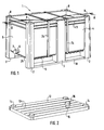
- a container 1 shown in perspective in FIG. 1 consists of longitudinal side walls 4 and transverse side walls 5 as well as a bottom 26 which has a corrugated bottom 9.
- the top of the container 1 closes a lid 12, as shown in Figure 2.
- the container 1 has four corner posts 2 and two middle posts 3 on the longitudinal side walls 4.
- the corner and middle posts 2, 3 form so-called uprights which are connected to one another by longitudinal cross members 10.
- the stability and stability of the container 1 is increased by the two longitudinal cross members 10.
- the corner posts 2 and the middle posts 3 are reinforced and protrude relative to the longitudinal and transverse side walls 4, 5.
- Container ribs 11 reinforce the upper area of the longitudinal and transverse side walls 4, 5 and run between the corner and middle posts 2, 3.
- the bottom 26 and the bottom underside 9 have a sufficient distance from the floor, which enables the fork of an underfloor vehicle to be easily brought under the underside of the floor in order to receive and transport the container 1.
- the outlet 6 which has an outlet closure 7 which is screwed onto a thread of the outlet 6, for example.
- the outlet 6 is as close as possible to the bottom 26 of the container 1.
- the underside 9 of the bottom is equipped with corrugated ribs which extend transversely to the longitudinal extent of the container 1.
- cross bands 24 are attached, which enclose the container 1 over its entire circumference. These cross bands run on the bottom bottom 9 in the depressions between two ribs and on the top of the container 1 below the lid, i.e. the lid rests on the cross belts 24.
- the cover 12 is shown in perspective, which is reinforced with cover ribs 13 in the longitudinal direction of the cover 12.
- cover ribs 13 At the four corners of the lid 12 there are upwardly curved knob receptacles 14, which are designed so that they rest on the knob 8 of the corner post 2 of the container 1 when it is closed with the lid.
- the inlet 15, which the inlet closure 16 closes, which is, for example, a rotary closure, is arranged near the one transverse edge of the cover 12.
- the inlet 15 can of course also be attached to a different location on the cover 12 than that shown.
- FIG. 3 shows a top view of the insert plate 17, which has holes 18 in several rows, the holes of adjacent rows being offset from one another.
- the container 1 there are generally a plurality of insert plates 17, the individual insert plate 17 separating adjacent layers of the goods to be stacked which are located one above the other.
- the holes 18 ensure that when the goods to be stacked are watered, water can flow freely from the one layer of stacked goods to the layer of stacked goods underneath.
- FIG. 4 shows a perspective top view of an end plate 19, which covers the uppermost layer of the stacked goods.
- the end plate 19 is provided with holes 20 and is reinforced by diagonal ribs 22 and transverse ribs 21.
- the reinforcement of the end plate 19 by the transverse ribs 21 and diagonal ribs 22 is necessary because the end plate 19, when the container 1 is filled with water, has to absorb high buoyancy forces and may. floats so far that it is pressed against the underside of the cover 12, whereby deformation and destruction can very easily occur with a non-reinforced end plate 19.
- the end plate 19 has a much higher weight than the insert plates 17 due to the transverse and longitudinal ribs and can therefore weigh down superimposed layers of the stacked goods accordingly, in order to counteract the strong buoyancy which, among other things. by air inclusions in the stacked goods and by the expansion of the stacked goods due to its moistening.
- the buoyancy of the stacked goods comes primarily from the fact that the specific weight of the stacked goods is somewhat smaller than the specific weight of water.
- FIG. 5 shows a longitudinal section through a container 1 which is filled with folding sleeves 23, which have the shape of caterpillars, for transport or shipping to the processor.
- the folding casings 23 are, for example, sausage casings which have to be watered before being filled with sausage meat so that they can be pushed onto a cornucopia of a filling machine in a smooth, stretchy manner.
- the container 1 shown accommodates, for example, five layers of folding sleeves 23, the first layer being located directly on the inside of the bottom 26.
- the individual layers of folding sleeves 23 are closed, ie the folding sleeves sit close together. In the drawing, gaps have been left in the individual layers for reasons of better clarity, while in practice the individual layer comprises folding sleeves 23 which are continuously adjacent to one another.
- the insert plates described above are located between the individual layers of the folding sleeves 23 17 with the holes 18.
- the insert plates 17 have some play with respect to the transverse side walls 5 and the longitudinal side walls 4, ie their edges do not rest against these walls.
- the uppermost layer of the stacked folding sleeves 23 is covered by the end plate 19, which has the holes 20, and is at a distance d from the top edge of the container 1 or, if this is closed with a lid 12, from the underside of the lid 12.
- This distance d is of the order of magnitude of the length of the standing folding sleeves 23 and serves to compensate for the buoyancy which arises from the washing of the folding sleeves 23.
- the buoyancy results from the lighter specific weight of the material of the folding sleeves compared to water, and from the expansion of the watered folding sleeves, which are up to about 1.5% longer than the length in the state watering, can enlarge.
- FIG. 6 of a container 1 closed with the lid 12 shows that two longitudinal bands 25, which are guided over the lid 12, enclose the container 1 between the lid ribs 13.
- transverse bands 24 which run between the upper edge of the container 1 and the lid 12 and also enclose the container 1.
- the container 1 is filled by the manufacturer of the folding sleeves for shipping with the dry folding sleeves 23, the insert plates 17 and the end plate 19 and serves as both a packaging and a transport container.
- the transverse straps 24 are first attached to both sides of the middle post 3, then the container is closed with the lid 12 and longitudinal straps 25 are placed over the outside of the lid 12 and passed around the container 1 and tensioned.
- the outlet 6 and the inlet 15 are generally closed.
- watering of the folding casings can be started at any time if necessary. This generally takes place over a period of at least 30 to 40 minutes and at water temperatures up to 50 ° C.
- the container 1 remains closed and enclosed by the longitudinal and transverse belts, and water is introduced into the container 1 via the open inlet 15.
- the folding sleeves 23 have been watered for a sufficient length of time, the longitudinal bands 25 and the cover 12 are removed, so that the folding sleeves 23 can be removed.
- the water can flow off partially or entirely via the open outlet 6 before the container 1 is opened, but also at a later point in time.
- the empty container 1 is reusable and will be returned to the manufacturer of the folding sleeves.
- the multiple function of the container 1 as a packaging, transport and washing container saves a great deal of time, since packaging of the folding sleeves for shipping is eliminated, as is unpacking and insertion into a container for watering. Another advantage is that the disposal of packaging waste is largely avoided.
Landscapes
- Engineering & Computer Science (AREA)
- Mechanical Engineering (AREA)
- Food Science & Technology (AREA)
- Packages (AREA)
- Cartons (AREA)
- External Artificial Organs (AREA)
Abstract
Description
- Die Erfindung betrifft einen mehrfunktionalen Behälter für die Verpackung, den Transport und die Wässerung von Falthüllen zur Umhüllung von einzeln abzufüllenden Produkten, wobei der durch Quer- und Längsseitenwände und einen Boden gebildete Behälter von einem abnehmbaren Deckel abgeschlossen ist und Eck- und Mittelpfosten als Steher aufweist, die durch Längstraversen miteinander verbunden sind.
- Derartige Behälter sind als Volumenbehälter mit Abmessungen gemäß der Euro-Norm für solche Behälter für die Verpackung und den Transport von Gütern bekannt.
- Auf dem Gebiet von gerafften Hüllen, die zu Raupen zusammengefügt sind und als Umhüllung von Nahrungsmitteln oder auch Nicht-Nahrungsmitteln verwendet werden, erfolgt beim Hersteller die Abpackung der Hüllen in Kartons, die im allgemeinen für den Transport zu dem Verarbeiter entweder einzeln oder zu mehreren mittels Schrumpffolien zu Transporteinheiten zusammengefaßt werden. Dabei ergibt sich das Problem, daß beim Verarbeiter durch die Verpackung sowohl Kartons als auch Folien als Abfall entsorgt werden müssen, was Zeit-, Platzprobleme und Kosten mit sich bringt. Die ausgepackten Hüllen müssen beim Verarbeiter auch noch vor dem Abfüllen gewässert werden, damit sie ohne Schwierigkeiten auf einen Fülldorn einer Füllmaschine aufgebracht werden können. Dies bedeutet, daß die ausgepackten Hüllen in einen Behälter eingebracht werden müssen, in welchem sie gewässert werden können, wodurch ein weiterer Arbeitsgang beim Verarbeiter erforderlich ist.
- Demgegenüber besteht die Aufgabe der Erfindung darin, einen Behälter der eingangs beschriebenen Art so zu verbessern, daß er mehrere Funktionen hintereinander erfüllen kann und darüberhinaus kein zu entsorgendes Verpakkungsmaterial für die Hüllen anfällt.
- Diese Aufgabe wird gemäß der Erfindung in der Weise gelöst, daß der Deckel mit einem Zulauf, den ein Zulaufverschluß abschließt, ausgestattet ist und daß in der einen Querseitenwand ein Ablauf mit einem Ablaufverschluß angebracht ist.
- In Ausgestaltung der Erfindung sind die Falthüllen stehend, in mehreren Lagen in dem Behälter gestapelt und sind die einzelnen Lagen durch Einlegeplatten voneinander getrennt. Dabei ist zweckmäßigerweise die oberste Lage der gestapelten Falthüllen von einer Abschlußplatte abgedeckt, die Löcher aufweist und durch Quer- und Diagonalrippen verstärkt ist.
- In Weiterbildung der Erfindung weist der Boden eine Bodenunterseite mit gewellten Rippen auf, die sich quer zur Längsausdehnung des Behälters erstrecken, und umschließen zu beiden Seiten der Mittelpfosten Querbänder den Behälter, die in den Senken zwischen zwei Rippen und unterhalb des Deckels verlaufen.
- Die weitere Ausgestaltung der Erfindung ergibt sich aus den Merkmalen der Patentansprüche 5 bis 10.
- Die Erfindung wird im folgenden anhand eines zeichnerisch dargestellten Ausführungsbeispiels näher erläutert. Es zeigen:
- Fig. 1
- eine perspektivische Ansicht des mehrfunktionalen Behälters, bei abgenommenen Deckel und verpackt mit Querbändern,
- Fig. 2
- eine perspektivische Ansicht des Deckels des Behälters nach Figur 1,
- Fig. 3
- eine Draufsicht auf eine gelochte Einlegeplatte, die zwei übereinander gestapelte Lagen von Falthüllen innerhalb des Behälters voneinander trennt,
- Fig. 4
- eine perspektivische Draufsicht auf eine gelochte und mit Rippen verstärkte Abschlußplatte als oberste Platte der übereinander gestapelten Lagen von Falthüllen innerhalb des Behälters,
- Fig. 5
- einen Längsschnitt entlang der Linie A-A in Figur 1 durch einen mit Falthüllen gefüllten, für den Transport vorbereiteten Behälter, bei abgenommenen Deckel und
- Fig. 6
- eine Draufsicht auf den mit einem Deckel verschlossenen und mit Quer- und Längsbändern verpackten Behälter.
- Ein in Figur 1 perspektivisch dargestellter Behälter 1 besteht aus Längsseitenwänden 4 und Querseitenwänden 5 sowie einem Boden 26, der eine gewellte Bodenunterseite 9 hat. Die Oberseite des Behälters 1 verschließt ein Deckel 12, wie er in Figur 2 dargestellt ist. In Figur 1 ist der Deckel abgenommen. Der Behälter 1 weist vier Eckpfosten 2 und zwei Mittelpfosten 3 an den Längsseitenwänden 4 auf. Die Eck- und Mittelpfosten 2, 3 bilden sogenannte Steher, die durch Längstraversen 10 miteinander verbunden sind. Durch die beiden Längstraversen 10 wird die Standfestigkeit und die Stabilität des Behälters 1 erhöht. Die Eckpfosten 2 und die Mittelpfosten 3 sind verstärkt ausgebildet und springen gegenüber den Längs- und Querseitenwänden 4, 5 vor. Behälterrippen 11 verstärken den oberen Bereich der Längs- und Querseitenwände 4, 5 und laufen zwischen den Eck- und Mittelpfosten 2, 3 um. Der Boden 26 bzw. die Boden-Unterseite 9 besitzen einen ausreichenden Bodenabstand, der es ermöglicht, daß die Gabel eines Unterflurfahrzeugs problemlos unter die Bodenunterseite gebracht werden kann, um den Behälter 1 aufzunehmen und zu transportieren.
- In der einen Querseitenwand 5 des Behälters 1 ist ein Ablauf 6 angebracht, der einen Ablaufverschluß 7 aufweist, der beispielsweise auf ein Gewinde des Ablaufs 6 aufgeschraubt ist. Wie aus Figur 1 ersichtlich ist, befindet sich der Ablauf 6 möglichst nahe dem Boden 26 des Behälters 1. Die Bodenunterseite 9 ist mit gewellten Rippen ausgestattet, die sich quer zur Längsausdehnung des Behälters 1 erstrecken. Zu beiden Seiten der Mittelpfosten 3 sind Querbänder 24 angebracht, die den Behälter 1 über seinen vollen Umfang umschließen. Diese Querbänder verlaufen auf der Bodenunterseite 9 in den Senken zwischen zwei Rippen und auf der Oberseite des Behälters 1 unterhalb des Deckels, d.h. der Deckel liegt auf den Querbändern 24 auf.
- In Figur 2 ist perspektivisch der Deckel 12 gezeigt, der mit Deckelrippen 13 in Längsrichtung des Deckels 12 verstärkt ist. An den vier Ecken des Deckels 12 befinden sich nach oben gewölbte Noppenaufnahmen 14, die so ausgebildet sind, daß sie auf Noppen 8 der Eckpfosten 2 des Behälters 1 aufliegen, wenn dieser mit dem Deckel verschlossen ist. Nahe der einen Querkante des Deckels 12 ist der Zulauf 15 angeordnet, den der Zulaufverschluß 16 abschließt, bei dem es sich beispielsweise um einen Drehverschluß handelt. Der Zulauf 15 kann selbstverständlich auch auf einer anderen Stelle des Deckels 12 als der gezeigten angebracht sein.
- In Figur 3 ist eine Draufsicht auf die Einlegeplatte 17 gezeigt, die Löcher 18 in mehreren Reihen aufweist, wobei die Löcher benachbarter Reihen zueinander versetzt sind. In dem Behälter 1 sind im allgemeinen mehrere Einlegeplatten 17 vorhanden, wobei die einzelne Einlegeplatte 17 benachbarte, übereinander befindliche Lagen des zu stapelnden Gutes voneinander trennt. Durch die Löcher 18 ist gewährleistet, daß beim Wässern des zu stapelnden Gutes Wasser ungehindert von der einen Lage Stapelgut zu der darunter befindlichen Lage Stapelgut fließen kann.
- Figur 4 zeigt eine perspektivische Draufsicht auf eine Abschlußplatte 19, die die oberste Lage des Stapelgutes abdeckt. Die Abschlußplatte 19 ist mit Löchern 20 ausgestattet und wird durch Diagonalrippen 22 und Querrippen 21 verstärkt. Die Verstärkung der Abschlußplatte 19 durch die Querrippen 21 und Diagonalrippen 22 ist erforderlich, da die Abschlußplatte 19, wenn der Behälter 1 mit Wasser gefüllt ist, hohe Auftriebskräfte aufnehmen muß und u.U. so weit aufschwimmt, daß sie gegen die Unterseite des Deckels 12 gedrückt wird, wodurch bei einer nichtverstärkten Abschlußplatte 19 sehr leicht Deformationen und auch Zerstörungen auftreten können. Hinzu kommt noch, daß die Abschlußplatte 19 durch die Quer- und Längsrippen ein wesentlich höheres Gewicht als die Einlegeplatten 17 hat und dadurch übereinanderliegende Lagen des Stapelgutes entsprechend beschweren kann, um dem starken Auftrieb entgegenzuwirken, der u.a. durch Lufteinschlüsse im Stapelgut und durch das Ausdehnen des Stapelguts infolge seiner Befeuchtung verstärkt wird. Der Auftrieb des Stapelgutes kommt dabei in erster Linie dadurch zustande, daß das spezifische Gewicht des Stapelgutes einiges kleiner als das spezifische Gewicht von Wasser ist.
- Figur 5 zeigt einen Längsschnitt durch einen Behälter 1, der für den Transport bzw. den Versand an den Verarbeiter mit Falthüllen 23 gefüllt ist, die die Gestalt von Raupen aufweisen. Bei den Falthüllen 23 handelt es sich beispielsweise um Wursthüllen, die vor dem Befüllen mit Wurstbrät gewässert werden müssen, damit sie geschmeidig, dehnbar und dadurch problemlos auf ein Füllhorn einer Füllmaschine aufgeschoben werden können. Der gezeigte Behälter 1 nimmt beispielsweise fünf Lagen von Falthüllen 23 auf, wobei die erste Lage unmittelbar auf der Innenseite des Bodens 26 aufsitzt. Die einzelnen Lagen von Falthüllen 23 sind geschlossen, d.h. die Falthüllen sitzen dicht nebeneinander. In der Zeichnung sind in den einzelnen Lagen aus Gründen der besseren Übersichtlichkeit Lücken gelassen worden, während in der Praxis die einzelne Lage durchgehend aneinander angrenzende Falthüllen 23 umfaßt. Zwischen den einzelnen Lagen der Falthüllen 23 befinden sich die voranstehend beschriebenen Einlegeplatten 17 mit den Löchern 18. Die Einlegeplatten 17 haben gegenüber den Querseitenwänden 5 und den Längsseitenwänden 4 etwas Spiel, d.h. sie liegen mit ihren Kanten nicht an diesen Wänden an. Die oberste Lage der gestapelten Falthüllen 23 ist von der Abschlußplatte 19 abgedeckt, die die Löcher 20 aufweist, und gegenüber der Oberkante des Behälters 1 bzw., falls dieser mit einem Deckel 12 verschlossen ist, gegenüber der Unterseite des Deckels 12 einen Abstand d aufweist. Dieser Abstand d liegt in der Größenordnung der Länge der stehenden Falthüllen 23 und dient zum Ausgleich des Auftriebs, der durch das Wässern der Falthüllen 23 entsteht. Wie zuvor schon erläutert wurde, ergibt sich der Auftrieb durch das leichtere spezifische Gewicht des Materials der Falthüllen, im Vergleich zu Wasser, und durch die Ausdehnung der gewässerten Falthüllen, die ihre Länge bis zu etwa 1,5 %, gegenüber der Länge im Zustand vor dem Wässern, vergrößern können.
- Ein Behälter 1, in welchem fünf Lagen von Falthüllen gestapelt sind, die jeweils durch Einlegeplatten 17 voneinander getrennt sind und eine oberste Lage von der Abschlußplatte 19 bedeckt ist, hat nach der Euro-Norm Außenmaße

- Die Draufsicht in Figur 6 auf einen mit dem Deckel 12 verschlossenen Behälter 1 läßt erkennen, daß zwischen den Deckelrippen 13 zwei Längsbänder 25, die über den Deckel 12 geführt sind, den Behälter 1 umschließen. Links und rechts von den Mittelpfosten 3 sind Querbänder 24 angeordnet, die zwischen der Oberkante des Behälters 1 und dem Deckel 12 verlaufen und gleichfalls den Behälter 1 umschließen.
- Der Behälter 1 wird von dem Hersteller der Falthüllen für den Versand mit den trockenen Falthüllen 23, den Einlegeplatten 17 und der Abschlußplatte 19 gefüllt und dient sowohl als Verpackungs- als auch als Transportbehälter. Für den Transport werden bei offenem Behälter 1 zunächst die Querbänder 24 zu beiden Seiten der Mittelpfosten 3 angebracht, danach wird der Behälter mit dem Deckel 12 verschlossen und Längsbänder 25 über die Außenseite des Deckels 12 gelegt und um den Behälter 1 herumgeführt und gespannt. Der Ablauf 6 und der Zulauf 15 sind dabei im allgemeinen geschlossen.
- Sobald der Behälter beim Weiterverarbeiter der Falthüllen, beispielsweise einem Metzger- oder Wurstwarenbetrieb, eingetroffen ist, kann bei Bedarf jederzeit mit dem Wässern der Falthüllen begonnen werden. Dies geschieht im allgemeinen über eine Zeitspanne von mindestens 30 bis 40 Minuten und bei Wassertemperaturen bis 50 °C. Während des Wässerns bleibt der Behälter 1 durch die Längs- und Querbänder ge- und umschlossen, und über den geöffneten Zulauf 15 wird Wasser in den Behälter 1 eingeleitet. Sobald die Falthüllen 23 ausreichend lang gewässert sind, werden die Längsbänder 25 und der Deckel 12 abgenommen, so daß die Falthüllen 23 entnommen werden können. Das Wasser kann schon vor dem Öffnen des Behälters 1, aber auch zu einem späteren Zeitpunkt, teilweise oder zur Gänze über den geöffneten Ablauf 6 abfließen. Der geleerte Behälter 1 ist wiederverwendbar und wird an den Hersteller der Falthüllen zurückgesandt.
- Durch die Mehrfachfunktion des Behälters 1 als Verpackungs-, Transport- und Wässerungsbehälter wird eine hohe Zeitersparnis erzielt, da das Verpacken der Falthüllen für den Versand entfällt, ebenso das Auspacken und Einlegen in einen Behälter zum Wässern. Ein weiterer Vorteil besteht darin, daß die Entsorgung von Verpackungsmüll größtenteils vermieden wird.
Claims (10)
- Mehrfunktionaler Behälter für die Verpackung, den Transport und die Wässerung von Falthüllen zur Umhüllung von einzeln abzufüllenden Produkten, wobei der durch Quer- und Längsseitenwände und einen Boden gebildete Behälter von einem abnehmbaren Deckel abgeschlossen ist und Eck- und Mittelpfosten als Steher aufweist, die durch Längstraversen miteinander verbunden sind, dadurch gekennzeichnet, daß der Deckel (12) mit einem Zulauf (15), den ein Zulaufverschluß (16) abschließt, ausgestattet ist und daß in der einen Querseitenwand (5) ein Ablauf (6) mit einem Ablaufverschluß (7) angebracht ist.
- Behälter nach Anspruch 1, dadurch gekennzeichnet, daß die Falthüllen (23) stehend, in mehreren Lagen in dem Behälter (1) gestapelt sind und daß die einzelnen Lagen durch gelochte Einlegeplatten (17) voneinander getrennt sind.
- Behälter nach Anspruch 2, dadurch gekennzeichnet, daß die oberste Lage der gestapelten Falthüllen (23) von einer Abschlußplatte (19) abgedeckt ist, die Löcher (20) aufweist und durch Quer(21)- und Diagonalrippen (22) verstärkt ist.
- Behälter nach Anspruch 1, dadurch gekennzeichnet, daß der Boden (26) eine Bodenunterseite (9) mit gewellten Rippen aufweist, die sich quer zur Längsausdehnung des Behälters (1) erstrecken und daß zu beiden Seiten der Mittelpfosten (3) Querbänder (24) den Behälter (1) umschließen, die in den Senken zwischen zwei Rippen und unterhalb des Deckels (12) verlaufen.
- Behälter nach Anspruch 1, dadurch gekennzeichnet, daß die Eckpfosten (2) und die Mittelpfosten (3) verstärkt sind, gegenüber den Längs-Querseitenwänden (4, 5) vorspringen und daß die Bodenunterseite (9) einen ausreichenden Bodenabstand aufweist, der die Aufnahme des Behälters (1) durch die Gabel eines Unterflurfahrzeugs zuläßt.
- Behälter nach Anspruch 1, dadurch gekennzeichnet, daß der Deckel (12) an den Ecken nach oben gewölbte Noppenaufnahmen (14) aufweist, die auf Noppen (8) der Eckpfosten (2) aufliegen.
- Behälter nach Anspruch 1, dadurch gekennzeichnet, daß zwei Längsbänder (25) außen den aufgesetzten Deckel (12) umschließen.
- Behälter nach Anspruch 1, dadurch gekennzeichnet, daß Behälterrippen (11) den oberen Bereich der Längs- und Querseitenwände (4, 5) verstärken und zwischen den Eck- und Mittelpfosten (2, 3) umlaufen.
- Behälter nach Anspruch 1, dadurch gekennzeichnet, daß der Deckel (12) durch Deckelrippen (13), die in Längsrichtung verlaufen, verstärkt ist.
- Behälter nach Anspruch 3, dadurch gekennzeichnet, daß die Abschlußplatte (19) einen Abstand d in der Größenordnung der Länge einer zu einer Raupe zusammengefügten Falthülle (23) von dem Deckel (12) einhält.
Applications Claiming Priority (2)
| Application Number | Priority Date | Filing Date | Title |
|---|---|---|---|
| DE19613068 | 1996-04-01 | ||
| DE19613068A DE19613068A1 (de) | 1996-04-01 | 1996-04-01 | Mehrfunktionaler Behälter |
Publications (2)
| Publication Number | Publication Date |
|---|---|
| EP0799771A1 true EP0799771A1 (de) | 1997-10-08 |
| EP0799771B1 EP0799771B1 (de) | 2000-06-28 |
Family
ID=7790202
Family Applications (1)
| Application Number | Title | Priority Date | Filing Date |
|---|---|---|---|
| EP97105092A Expired - Lifetime EP0799771B1 (de) | 1996-04-01 | 1997-03-26 | Mehrfunktionaler Behälter |
Country Status (6)
| Country | Link |
|---|---|
| US (1) | US5794779A (de) |
| EP (1) | EP0799771B1 (de) |
| AT (1) | ATE194118T1 (de) |
| DE (2) | DE19613068A1 (de) |
| DK (1) | DK0799771T3 (de) |
| ES (1) | ES2149523T3 (de) |
Families Citing this family (10)
| Publication number | Priority date | Publication date | Assignee | Title |
|---|---|---|---|---|
| GR1006814B (el) * | 2009-07-06 | 2010-06-25 | Παναγιωτης Κωνσταντινου Σαρμας | Δεξαμενη ωριμανσης και αποθηκευσης μαλακων τυριων αλμης |
| WO2012044940A2 (en) | 2010-10-01 | 2012-04-05 | Sara Lee Corporation | Systems and methods for providing a food product with additives |
| US9380804B2 (en) | 2012-07-12 | 2016-07-05 | The Hillshire Brands Company | Systems and methods for food product extrusion |
| CH707000A1 (de) | 2012-09-21 | 2014-03-31 | Kalt Maschb Ag | Käseform. |
| CA2943685A1 (en) | 2015-11-13 | 2017-05-13 | Kalt Maschinenbau Ag | A method and a device for the handling of cheese blocks |
| EP3167723A1 (de) | 2015-11-13 | 2017-05-17 | Kalt Maschinenbau AG | Verfahren und vorrichtung zur handhabung von käselaiben |
| CH712381B1 (de) | 2016-04-21 | 2021-05-14 | Kalt Maschb Ag | Käsefertiger. |
| CH714488A2 (de) | 2017-12-21 | 2019-06-28 | Kalt Maschb Ag | Pressdeckel für eine Käseform. |
| CH715264A2 (de) | 2018-08-20 | 2020-02-28 | Kalt Maschb Ag | Vorrichtung zur Käseherstellung. |
| CH716326A2 (de) | 2019-06-17 | 2020-12-30 | Kalt Maschb Ag | Verfahren und Vorrichtung zur Herstellung von Kräuterkäse. |
Citations (5)
| Publication number | Priority date | Publication date | Assignee | Title |
|---|---|---|---|---|
| US3471305A (en) * | 1966-06-13 | 1969-10-07 | Union Carbide Corp | Packaging of shirred food casings and package |
| US3904030A (en) * | 1973-05-10 | 1975-09-09 | Emerson Electric Co | Returnable packaging system |
| EP0212363A2 (de) * | 1985-08-22 | 1987-03-04 | Teepak, Inc. | Verpackung von nichtplissierten rohrförmigen Nahrungsumhüllungen |
| US5105947A (en) * | 1985-10-04 | 1992-04-21 | Plastech International, Inc. | Container having a replaceable pallet base |
| EP0482390A1 (de) * | 1990-10-10 | 1992-04-29 | Flemming Elvin-Jensen | Doppelwandiger Behälter |
Family Cites Families (2)
| Publication number | Priority date | Publication date | Assignee | Title |
|---|---|---|---|---|
| US5382190A (en) * | 1993-03-12 | 1995-01-17 | Viskase Corporation | Package of shirred food casings |
| DE4341338A1 (de) * | 1993-12-04 | 1995-06-08 | Schuetz Werke Gmbh Co Kg | Metallbehälter für den Transport und die Lagerung von Flüssigkeiten |
-
1996
- 1996-04-01 DE DE19613068A patent/DE19613068A1/de not_active Withdrawn
-
1997
- 1997-03-18 US US08/820,651 patent/US5794779A/en not_active Expired - Fee Related
- 1997-03-26 ES ES97105092T patent/ES2149523T3/es not_active Expired - Lifetime
- 1997-03-26 DK DK97105092T patent/DK0799771T3/da active
- 1997-03-26 AT AT97105092T patent/ATE194118T1/de not_active IP Right Cessation
- 1997-03-26 EP EP97105092A patent/EP0799771B1/de not_active Expired - Lifetime
- 1997-03-26 DE DE59701927T patent/DE59701927D1/de not_active Expired - Lifetime
Patent Citations (5)
| Publication number | Priority date | Publication date | Assignee | Title |
|---|---|---|---|---|
| US3471305A (en) * | 1966-06-13 | 1969-10-07 | Union Carbide Corp | Packaging of shirred food casings and package |
| US3904030A (en) * | 1973-05-10 | 1975-09-09 | Emerson Electric Co | Returnable packaging system |
| EP0212363A2 (de) * | 1985-08-22 | 1987-03-04 | Teepak, Inc. | Verpackung von nichtplissierten rohrförmigen Nahrungsumhüllungen |
| US5105947A (en) * | 1985-10-04 | 1992-04-21 | Plastech International, Inc. | Container having a replaceable pallet base |
| EP0482390A1 (de) * | 1990-10-10 | 1992-04-29 | Flemming Elvin-Jensen | Doppelwandiger Behälter |
Also Published As
| Publication number | Publication date |
|---|---|
| DK0799771T3 (da) | 2000-08-28 |
| EP0799771B1 (de) | 2000-06-28 |
| DE19613068A1 (de) | 1997-10-02 |
| ATE194118T1 (de) | 2000-07-15 |
| US5794779A (en) | 1998-08-18 |
| DE59701927D1 (de) | 2000-08-03 |
| ES2149523T3 (es) | 2000-11-01 |
Similar Documents
| Publication | Publication Date | Title |
|---|---|---|
| DE69734342T2 (de) | Umhüllender verpackungsträger mit einer oberen trennlasche | |
| DE2449952C3 (de) | Zellenschachtel für Eier | |
| DE3137726A1 (de) | Wellpappenbehaelter | |
| DE1586583A1 (de) | Verpackungsbehaelter | |
| DE69500528T2 (de) | Behälter | |
| DE2633642C3 (de) | Versandschachtel mit Palette aus Pappe | |
| CH620403A5 (de) | ||
| EP3105131B1 (de) | Verpackung für einen flexiblen behälter und transporteinheit | |
| EP0799771A1 (de) | Mehrfunktionaler Behälter | |
| DE2020465A1 (de) | Verpackungsbehaelter und ihre Herstellung | |
| DE4343960C2 (de) | Vorrichtung zum Sammeln und Verpacken von Verpackungen sowie Verwendung der Vorrichtung | |
| DE69125287T2 (de) | Verfahren zum herstellen einer schachtel mit integrierten eckenverstärkungen | |
| DE7118186U (de) | Schale zum Verpacken von Fleisch und dergl. | |
| DE29606060U1 (de) | Mehrfunktionaler Behälter | |
| DE2529429B2 (de) | Aufgussbeutel und verfahren zum verpacken von aufgussbeuteln | |
| CH539548A (de) | Aus mindestens einem Zuschnitt aus faltbarem steifem Werkstoff gefalteter Behälter mit Boden und Seitenteilen | |
| AT407147B (de) | Verpackung für in achterschleifen gelegtes, drahtförmiges material | |
| DE29708292U1 (de) | Häcksler-Verpackungsbehälter | |
| DE29712092U1 (de) | Grossverpackung für Massengut | |
| DE19954006B4 (de) | Verpackung, insbesondere aus Wellpappe | |
| DE2128214A1 (de) | Faltkarton | |
| DE202012000998U1 (de) | Flexibler Schüttgutbehälter | |
| AT385965B (de) | Rechteckbehaelter | |
| DE3939948C1 (de) | ||
| DE29502427U1 (de) | Großbeutel für schütt- und/oder fließfähige Güter |
Legal Events
| Date | Code | Title | Description |
|---|---|---|---|
| PUAI | Public reference made under article 153(3) epc to a published international application that has entered the european phase |
Free format text: ORIGINAL CODE: 0009012 |
|
| AK | Designated contracting states |
Kind code of ref document: A1 Designated state(s): AT BE DE DK ES FI FR GB GR IE IT NL PT SE |
|
| 17P | Request for examination filed |
Effective date: 19971024 |
|
| 17Q | First examination report despatched |
Effective date: 19990119 |
|
| GRAG | Despatch of communication of intention to grant |
Free format text: ORIGINAL CODE: EPIDOS AGRA |
|
| RAP1 | Party data changed (applicant data changed or rights of an application transferred) |
Owner name: KALLE NALO GMBH & CO. KG |
|
| GRAG | Despatch of communication of intention to grant |
Free format text: ORIGINAL CODE: EPIDOS AGRA |
|
| GRAH | Despatch of communication of intention to grant a patent |
Free format text: ORIGINAL CODE: EPIDOS IGRA |
|
| RBV | Designated contracting states (corrected) |
Designated state(s): AT BE DE DK ES FI FR GB GR IE IT NL PT SE |
|
| GRAH | Despatch of communication of intention to grant a patent |
Free format text: ORIGINAL CODE: EPIDOS IGRA |
|
| GRAA | (expected) grant |
Free format text: ORIGINAL CODE: 0009210 |
|
| ITF | It: translation for a ep patent filed | ||
| AK | Designated contracting states |
Kind code of ref document: B1 Designated state(s): AT BE DE DK ES FI FR GB GR IE IT NL PT SE |
|
| REF | Corresponds to: |
Ref document number: 194118 Country of ref document: AT Date of ref document: 20000715 Kind code of ref document: T |
|
| REG | Reference to a national code |
Ref country code: IE Ref legal event code: FG4D Free format text: GERMAN |
|
| REF | Corresponds to: |
Ref document number: 59701927 Country of ref document: DE Date of ref document: 20000803 |
|
| ET | Fr: translation filed | ||
| REG | Reference to a national code |
Ref country code: DK Ref legal event code: T3 |
|
| GBT | Gb: translation of ep patent filed (gb section 77(6)(a)/1977) |
Effective date: 20000901 |
|
| PG25 | Lapsed in a contracting state [announced via postgrant information from national office to epo] |
Ref country code: PT Free format text: LAPSE BECAUSE OF FAILURE TO SUBMIT A TRANSLATION OF THE DESCRIPTION OR TO PAY THE FEE WITHIN THE PRESCRIBED TIME-LIMIT Effective date: 20000928 |
|
| PG25 | Lapsed in a contracting state [announced via postgrant information from national office to epo] |
Ref country code: GR Free format text: LAPSE BECAUSE OF FAILURE TO SUBMIT A TRANSLATION OF THE DESCRIPTION OR TO PAY THE FEE WITHIN THE PRESCRIBED TIME-LIMIT Effective date: 20000929 |
|
| REG | Reference to a national code |
Ref country code: ES Ref legal event code: FG2A Ref document number: 2149523 Country of ref document: ES Kind code of ref document: T3 |
|
| PG25 | Lapsed in a contracting state [announced via postgrant information from national office to epo] |
Ref country code: IE Free format text: LAPSE BECAUSE OF NON-PAYMENT OF DUE FEES Effective date: 20010309 |
|
| REG | Reference to a national code |
Ref country code: IE Ref legal event code: FD4D |
|
| PLBE | No opposition filed within time limit |
Free format text: ORIGINAL CODE: 0009261 |
|
| STAA | Information on the status of an ep patent application or granted ep patent |
Free format text: STATUS: NO OPPOSITION FILED WITHIN TIME LIMIT |
|
| 26N | No opposition filed | ||
| REG | Reference to a national code |
Ref country code: GB Ref legal event code: IF02 |
|
| PGFP | Annual fee paid to national office [announced via postgrant information from national office to epo] |
Ref country code: NL Payment date: 20060305 Year of fee payment: 10 |
|
| PGFP | Annual fee paid to national office [announced via postgrant information from national office to epo] |
Ref country code: FR Payment date: 20060308 Year of fee payment: 10 |
|
| PGFP | Annual fee paid to national office [announced via postgrant information from national office to epo] |
Ref country code: AT Payment date: 20060313 Year of fee payment: 10 |
|
| PGFP | Annual fee paid to national office [announced via postgrant information from national office to epo] |
Ref country code: FI Payment date: 20060314 Year of fee payment: 10 |
|
| PGFP | Annual fee paid to national office [announced via postgrant information from national office to epo] |
Ref country code: IT Payment date: 20060331 Year of fee payment: 10 |
|
| PGFP | Annual fee paid to national office [announced via postgrant information from national office to epo] |
Ref country code: ES Payment date: 20060425 Year of fee payment: 10 |
|
| PGFP | Annual fee paid to national office [announced via postgrant information from national office to epo] |
Ref country code: BE Payment date: 20060512 Year of fee payment: 10 |
|
| PG25 | Lapsed in a contracting state [announced via postgrant information from national office to epo] |
Ref country code: FI Free format text: LAPSE BECAUSE OF NON-PAYMENT OF DUE FEES Effective date: 20070326 |
|
| PG25 | Lapsed in a contracting state [announced via postgrant information from national office to epo] |
Ref country code: SE Free format text: LAPSE BECAUSE OF NON-PAYMENT OF DUE FEES Effective date: 20070327 |
|
| EUG | Se: european patent has lapsed | ||
| PG25 | Lapsed in a contracting state [announced via postgrant information from national office to epo] |
Ref country code: AT Free format text: LAPSE BECAUSE OF NON-PAYMENT OF DUE FEES Effective date: 20070326 |
|
| GBPC | Gb: european patent ceased through non-payment of renewal fee |
Effective date: 20070326 |
|
| NLV4 | Nl: lapsed or anulled due to non-payment of the annual fee |
Effective date: 20071001 |
|
| BERE | Be: lapsed |
Owner name: *KALLE NALO G.M.B.H. & CO. K.G. Effective date: 20070331 |
|
| PG25 | Lapsed in a contracting state [announced via postgrant information from national office to epo] |
Ref country code: BE Free format text: LAPSE BECAUSE OF NON-PAYMENT OF DUE FEES Effective date: 20070331 |
|
| REG | Reference to a national code |
Ref country code: FR Ref legal event code: ST Effective date: 20071130 |
|
| PG25 | Lapsed in a contracting state [announced via postgrant information from national office to epo] |
Ref country code: NL Free format text: LAPSE BECAUSE OF NON-PAYMENT OF DUE FEES Effective date: 20071001 |
|
| PGFP | Annual fee paid to national office [announced via postgrant information from national office to epo] |
Ref country code: SE Payment date: 20060306 Year of fee payment: 10 |
|
| PG25 | Lapsed in a contracting state [announced via postgrant information from national office to epo] |
Ref country code: GB Free format text: LAPSE BECAUSE OF NON-PAYMENT OF DUE FEES Effective date: 20070326 |
|
| REG | Reference to a national code |
Ref country code: ES Ref legal event code: FD2A Effective date: 20070327 |
|
| PG25 | Lapsed in a contracting state [announced via postgrant information from national office to epo] |
Ref country code: FR Free format text: LAPSE BECAUSE OF NON-PAYMENT OF DUE FEES Effective date: 20070402 Ref country code: ES Free format text: LAPSE BECAUSE OF NON-PAYMENT OF DUE FEES Effective date: 20070327 |
|
| PGFP | Annual fee paid to national office [announced via postgrant information from national office to epo] |
Ref country code: GB Payment date: 20060322 Year of fee payment: 10 |
|
| PG25 | Lapsed in a contracting state [announced via postgrant information from national office to epo] |
Ref country code: IT Free format text: LAPSE BECAUSE OF NON-PAYMENT OF DUE FEES Effective date: 20070326 |
|
| PGFP | Annual fee paid to national office [announced via postgrant information from national office to epo] |
Ref country code: DK Payment date: 20100319 Year of fee payment: 14 |
|
| PGFP | Annual fee paid to national office [announced via postgrant information from national office to epo] |
Ref country code: DE Payment date: 20110330 Year of fee payment: 15 |
|
| REG | Reference to a national code |
Ref country code: DK Ref legal event code: EBP |
|
| PG25 | Lapsed in a contracting state [announced via postgrant information from national office to epo] |
Ref country code: DK Free format text: LAPSE BECAUSE OF NON-PAYMENT OF DUE FEES Effective date: 20110331 |
|
| REG | Reference to a national code |
Ref country code: DE Ref legal event code: R119 Ref document number: 59701927 Country of ref document: DE Effective date: 20121002 |
|
| PG25 | Lapsed in a contracting state [announced via postgrant information from national office to epo] |
Ref country code: DE Free format text: LAPSE BECAUSE OF NON-PAYMENT OF DUE FEES Effective date: 20121002 |