EP0799779A2 - Verteileinrichtung - Google Patents
Verteileinrichtung Download PDFInfo
- Publication number
- EP0799779A2 EP0799779A2 EP96118507A EP96118507A EP0799779A2 EP 0799779 A2 EP0799779 A2 EP 0799779A2 EP 96118507 A EP96118507 A EP 96118507A EP 96118507 A EP96118507 A EP 96118507A EP 0799779 A2 EP0799779 A2 EP 0799779A2
- Authority
- EP
- European Patent Office
- Prior art keywords
- conveyor
- articles
- conveying
- conveying device
- belt
- Prior art date
- Legal status (The legal status is an assumption and is not a legal conclusion. Google has not performed a legal analysis and makes no representation as to the accuracy of the status listed.)
- Granted
Links
- 230000001360 synchronised effect Effects 0.000 claims abstract description 4
- 238000006073 displacement reaction Methods 0.000 claims description 22
- 238000000151 deposition Methods 0.000 claims 1
- 230000001771 impaired effect Effects 0.000 description 3
- 238000000034 method Methods 0.000 description 3
- 239000011449 brick Substances 0.000 description 1
- 230000008021 deposition Effects 0.000 description 1
- 238000001514 detection method Methods 0.000 description 1
- 230000000149 penetrating effect Effects 0.000 description 1
- 230000035515 penetration Effects 0.000 description 1
Images
Classifications
-
- B—PERFORMING OPERATIONS; TRANSPORTING
- B65—CONVEYING; PACKING; STORING; HANDLING THIN OR FILAMENTARY MATERIAL
- B65G—TRANSPORT OR STORAGE DEVICES, e.g. CONVEYORS FOR LOADING OR TIPPING, SHOP CONVEYOR SYSTEMS OR PNEUMATIC TUBE CONVEYORS
- B65G47/00—Article or material-handling devices associated with conveyors; Methods employing such devices
- B65G47/74—Feeding, transfer, or discharging devices of particular kinds or types
- B65G47/84—Star-shaped wheels or devices having endless travelling belts or chains, the wheels or devices being equipped with article-engaging elements
- B65G47/841—Devices having endless travelling belts or chains equipped with article-engaging elements
-
- B—PERFORMING OPERATIONS; TRANSPORTING
- B65—CONVEYING; PACKING; STORING; HANDLING THIN OR FILAMENTARY MATERIAL
- B65G—TRANSPORT OR STORAGE DEVICES, e.g. CONVEYORS FOR LOADING OR TIPPING, SHOP CONVEYOR SYSTEMS OR PNEUMATIC TUBE CONVEYORS
- B65G47/00—Article or material-handling devices associated with conveyors; Methods employing such devices
- B65G47/52—Devices for transferring articles or materials between conveyors i.e. discharging or feeding devices
- B65G47/68—Devices for transferring articles or materials between conveyors i.e. discharging or feeding devices adapted to receive articles arriving in one layer from one conveyor lane and to transfer them in individual layers to more than one conveyor lane or to one broader conveyor lane, or vice versa, e.g. combining the flows of articles conveyed by more than one conveyor
- B65G47/71—Devices for transferring articles or materials between conveyors i.e. discharging or feeding devices adapted to receive articles arriving in one layer from one conveyor lane and to transfer them in individual layers to more than one conveyor lane or to one broader conveyor lane, or vice versa, e.g. combining the flows of articles conveyed by more than one conveyor the articles being discharged or distributed to several distinct separate conveyors or to a broader conveyor lane
Definitions
- the invention relates to a distribution device with a first conveying device which conveys articles one behind the other, a second or further conveying device / s which is arranged above the first conveying device and a displacement device which converts predetermined articles from the first conveying device to the second or a further conveying device.
- an article flow conveyed to a transporter is distributed to two or more transporters, for example because of the limited output of subsequent processing devices.
- the displacement device has means with which predetermined articles can be selectively lifted from the first conveyor device, with which these lifted articles can be transported synchronously with the first conveyor device into a receiving area of the second or a further conveyor device and with which the articles on the second or another conveyor can be placed in the receiving area.
- This displacement device is that it does not impair the conveying speed of the first conveying device.
- the conveying devices have chains or V-belts.
- the displacement device can have a belt, to which saddles are attached, which engage in the first conveying device from below between the chains or V-belts.
- the saddles form the means by which the predetermined articles are lifted off, transported further and placed on the second or a further conveying device.
- the belt runs at the same speed as that of the first conveyor.
- the second or a further conveyor device is also driven synchronously with the first conveyor device and with the displacement device. Furthermore, the conveying plane of the second or a further conveying device can be arranged parallel to the conveying plane of the first conveying device for a particularly simple deposition of the converted articles.
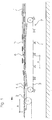
- FIG. 1 shows a side view of the distribution device according to the invention.
- Articles 2 are conveyed on a first conveyor device 1.
- the conveyor device 1 consists of two or more spaced-apart chains, belt or V-belts (not shown) which are rotated in the direction of the arrow by means of a motor.
- the articles 2 lie one behind the other on the chains or V-belts and are thus conveyed in the direction of the arrow by the conveyor device 1.
- a further second conveyor device 5 is provided, onto which predetermined articles from the article stream of the conveyor device 1 are to be distributed.
- This conveyor device 5 also consists of spaced-apart chains or V-belts, which are driven by another or the same motor. At the left end (FIG.
- the conveying device 5 has deflection rollers which are advantageously spaced apart in the same way as the chains or V-belts.
- the distribution device according to the invention contains a displacement device 7.
- this displacement device 7 has a band 3 to which saddles 4 are attached. The distance at which the saddles 4 are attached to the belt 3 corresponds to a multiple of the distance at which the articles 2 are conveyed on the conveyor device 1.
- the belt 3 of the displacement device 7 is driven at the same speed as that of the first conveyor device 1.
- the band 3 is deflected so that the saddles 4 attached to it from below through the chains or V-belts of the first Pass through conveyor 1, to the extent that the upper surface of the penetrating saddles reaches a height which is slightly above the conveyor level of the second conveyor 5, but the belt 3 of the displacement device 7 always below the chains or V-belts of the first conveyor 1 remains.
- the saddles 4 reach their highest point in the receiving area of the second conveyor device 5, which is located behind the deflection rollers 6 with respect to the conveying direction. After the saddles 4 have reached their highest point in the receiving area of the second conveyor 5, the band 3 of the displacement device 7 is guided so that the saddles 4 move again to a level below the conveyor 1 and then no longer reach through the first conveyor 1 .
- the two conveying devices 1, 5 and the displacement device 7 are advantageously driven at the same speed.
- the articles 2 lie at a predetermined distance on the chains or V-belts of the first conveyor device 1 and are conveyed by them in the direction of the arrow to the right.
- the saddles 4 are moved in the direction of the articles 2 by means of the belt 3 of the displacement device 7.
- the arrangement of the articles 2 on the conveyor 1 is so synchronized with the movement of the saddles 4 of the displacement device 7 that whenever an saddle reaches through the distance of the chains or V-belts of the first conveyor 1, an article 2 is arranged above it.
- the distance A of the saddles 4 is twice as large as the predetermined distance with which the articles 2 are conveyed on the first conveyor device 1, a saddle 4 engages under the chains or below every second article of the first conveyor device 1 V-belt through. With this penetration, the articles 2 are lifted from the saddle 4 by the first conveyor device 1. Thereupon they are no longer moved by the chains or V-belts of the first conveyor device 1. But since the tape of the transfer device 7 with the same horizontal speed as the chains or V-belts of the first conveyor 1 moves, the lifted article 2 lying on a saddle 4 is moved horizontally at the same horizontal speed and raised vertically to the maximum height of the saddle 4. At this highest point, the saddle 4 is located in the receiving area of the second conveyor device 5.
- the lifted article 2 is located above the conveying plane of the second conveyor device 5. At this height, the saddle 4 moves horizontally until it is also in spaced chains or V-belt engages the second conveyor 5. If the saddle 4 is then moved down again by guiding the belt 3 of the displacement device 7, the article 2 located on the saddle 4 is placed on the second conveyor device 5 and conveyed further by the latter.
- the speed of the article flow of the first conveying device 1 is in no way impaired by the repositioning.
- the arrangement of the saddles 4 on the belt 3 can be used to determine which article 2 is to be removed from the article flow of the first conveyor belt 1.
- the distribution device according to the invention becomes very flexible by simply moving the saddles 4 on the belt 3. Furthermore, complicated gripping or grasping of the articles to be distributed is not necessary, since they are simply lifted out of the first conveying device by the saddles 4.
Landscapes
- Engineering & Computer Science (AREA)
- Mechanical Engineering (AREA)
- Intermediate Stations On Conveyors (AREA)
- Structure Of Belt Conveyors (AREA)
- Branching, Merging, And Special Transfer Between Conveyors (AREA)
- Spinning Methods And Devices For Manufacturing Artificial Fibers (AREA)
Abstract
Description
- Die Erfindung betrifft eine Verteileinrichtung mit einer ersten Fördervorrichtung, die Artikel hintereinanderliegend fördert, einer zweiten oder weiteren Fördervorrichtung/en, die oberhalb der ersten Fördervorrichtung angeordnet ist und einer Versetzeinrichtung, welche vorbestimmte Artikel von der ersten Fördervorrichtung zur zweiten oder einer weiteren Fördervorrichtung umsetzt.
- Bei derartigen Verteileinrichtungen wird ein auf einen Transporteur geförderter Artikelstrom zum Beispiel wegen der begrenzten Leistung nachfolgender Bearbeitungseinrichtungen auf zwei oder mehr Transporteure verteilt.
- Bekannt ist es, den Artikelstrom mittels Weichen zu verteilen. Dabei werden die Artikel auf einer ersten Transportbahn, die beispielsweise durch zwei parallel verlaufende Keilriemen gebildet wird, hintereinanderliegend gefördert. Zur Verteilung einer bestimmten Anzahl von Artikeln wird eine Weiche, die beispielsweise von einer zweiten Transportbahn mit enger zusammenliegenden Keilriemen gebildet wird, in die erste Transportbahn eingetaucht. Die nun nachfolgenden Artikel werden mittels der Weiche umgelenkt und können so durch diese auf andere Transportbahnen verteilt werden. Der Vorgang wird beendet, indem die Weiche wieder aus der ersten Transportbahn herausgeschwenkt wird. Nachteilig bei dieser Einrichtung ist jedoch, daß der Zeitaufwand für das Eintauchen und Ausschwenken der Weiche die Leistung der Fördervorrichtung begrenzt.
- Weiterhin ist bekannt, mit einer Vorrichtung mit kreisförmig umlaufenden Gabeln oder Klemmvorrichtungen Artikel wahlweise oder alternierend aus einem Artikelstrom von einem ersten Förderband abzuheben und auf eine zweiter darüberliegende Transportbahn abzusetzen. Nachteilig an dieser Vorrichtung ist, daß durch die Richtungsänderung der Ziegel zum Zeitpunkt des Abhebens die Förderleistung begrenzt wird. Ferner wird die Förderleistung durch den komplizierten Klemm- bzw. Greifvorgang, mit dem die umlaufenden Gabeln die Artikel erfassen, begrenzt.
- Somit ist es die Aufgabe der vorliegenden Erfindung, eine Vorrichtung zu schaffen, mit der vorbestimmte Artikel aus einem Artikelstrom herausgenommen werden können, ohne daß die Geschwindigkeit des Artikelstroms durch den Verteilvorgang beeinträchtigt wird.
- Diese Aufgabe wird erfindungsgemäß durch die Merkmale des Patentanspruches 1 gelöst. Weitere Ausgestaltungen ergeben sich aus den Unteransprüchen.
- Bei der erfindungsgemäßen Verteileinrichtung werden Artikel, die hintereinanderliegend auf einer ersten Fördervorrichtung gefördert werden, mittels einer Versetzeinrichtung auf eine zweite oder weitere Fördervorrichtung/en, die oberhalb der ersten Fördervorrichtung angeordnet ist, umgesetzt. Die Versetzeinrichtung weist Mittel auf, mit denen vorbestimmte Artikel von der ersten Fördervorrichtung selektiv abgehoben werden können, mit denen diese abgehobenen Artikel synchron mit der ersten Fördervorrichtung in einen Aufnahmebereich der zweiten oder einer weiteren Fördervorrichtung transportiert werden können und mit denen die Artikel auf der zweiten oder einer weiteren Fördervorrichtung in dessen Aufnahmebereich abgesetzt werden können. Besonders vorteilhaft an dieser Versetzeinrichtung ist, daß sie die Fördergeschwindigkeit der ersten Fördervorrichtung nicht beeinträchtigt.
- In einer weiteren Ausgestaltung der Erfindung weisen die Fördervorrichtungen Ketten oder Keilriemen auf. Ferner kann die Versetzeinrichtung ein Band aufweisen, an welchem Sättel befestigt sind, die in die erste Fördervorrichtung von unten zwischen den Ketten oder Keilriemen eingreifen. Die Sättel bilden dabei die Mittel, mit denen die vorbestimmten Artikel abgehoben, weitertransportiert und auf der zweiten oder einer weiteren Fördervorrichtung abgesetzt werden. Dabei läuft das Band mit der gleichen Geschwindigkeit wie die der ersten Fördervorrichtung. Durch diese Synchronisation der Fördergeschwindigkeit, mit der die Artikel gefördert werden, mit der Geschwindigkeit des Bandes der Versetzeinrichtung wird wiederum erreicht, daß die Geschwindigkeit des Artikelstroms nicht beeinträchtigt wird. Desweiteren ist an dieser Ausgestaltung vorteilhaft, daß das Erfassen der vorbestimmten Artikel in besonders einfacher Weise durch ein Abheben dieser aufgrund der von unten durchgreifenden Sättel erfolgt.
- In einer weiteren vorteilhaften Ausgestaltung der Erfindung wird auch die zweite oder eine weitere Fördervorrichtung synchron mit der ersten Fördervorrichtung und mit der Versetzeinrichtung angetrieben. Ferner kann für ein besonderes einfaches Absetzen der umgesetzten Artikel die Förderebene der zweiten oder einer weiteren Fördervorrichtung parallel zur Förderebene der ersten Fördervorrichtung angeordnet sein.
- Ein Ausführungsbeispiel der Erfindung ist in der Zeichnung dargestellt und wird im folgenden näher beschrieben.
- Die einzige Figur 1 zeigt eine Seitenansicht der erfindungsgemäßen Verteileinrichtung.
- Es werden die Artikel 2 auf einer ersten Fördervorrichtung 1 gefördert. Die Fördervorrichtung 1 besteht aus zwei oder mehreren zueinander beabstandeten Ketten, Band- oder Keilriemen (nicht gezeigt), die mittels eines Motors in Richtung des Pfeils gedreht werden. Die Artikel 2 liegen hintereinander auf den Ketten oder Keilriemen und werden somit in Richtung des Pfeils von der Fördervorrichtung 1 gefördert. Ferner ist eine weitere zweite Fördervorrichtung 5 vorgesehen, auf die vorbestimmte Artikel aus dem Artikelstrom der Fördervorrichtung 1 verteilt werden sollen. Auch diese Fördervorrichtung 5 besteht aus zueinander beabstandeten Ketten oder Keilriemen, die von einem weiteren oder dem gleichen Motor angetrieben werden. Am linken Ende (Figur 1) weist die Fördervorrichtung 5 Umlenkrollen auf, die vorteilhafterweise in gleicher Weise wie die Ketten oder Keilriemen beabstandet sind. Ferner enthält die erfindungsgemäße Verteileinrichtung eine Versetzeinrichtung 7. Diese Versetzeinrichtung 7 weist in einem vorteilhaften Ausführungsbeispiel der Erfindung ein Band 3 auf, an dem Sättel 4 befestigt sind. Der Abstand, mit dem die Sättel 4 an dem Band 3 befestigt sind, entspricht einem Vielfachen des Abstands, mit dem die Artikel 2 auf der Fördervorrichtung 1 gefördert werden. Das Band 3 der Versetzeinrichtung 7 wird mit der gleichen Geschwindigkeit wie die der ersten Fördervorrichtung 1 angetrieben. Dabei wird das Band 3 so umgelenkt, daß die auf ihm befestigten Sättel 4 von unten durch die Ketten oder Keilriemen der ersten Fördervorrichtung 1 durchgreifen, und zwar soweit, daß die obere Fläche der durchgreifenden Sättel bis zu einer Höhe gelangt, die etwas oberhalb der Förderebene der zweiten Fördervorrichtung 5 ist, wobei jedoch das Band 3 der Versetzeinrichtung 7 immer unterhalb von den Ketten oder Keilriemen der ersten Fördervorrichtung 1 bleibt. Dabei erreichen die Sättel 4 ihren höchsten Punkt im Aufnahmebereich der zweiten Fördervorrichtung 5, der sich bezüglich der Förderrichtung hinter den Umlenkrollen 6 befindet. Nachdem die Sättel 4 ihren höchsten Punkt im Aufnahmebereich der Zweiten Fördervorrichtung 5 erreicht haben, ist das Band 3 der Versetzeinrichtung 7 so geführt, daß sich die Sättel 4 wieder auf ein Niveau unterhalb der Fördervorrichtung 1 bewegen und dann nicht mehr durch die erste Fördervorrichtung 1 greifen.
- Vorteilhafterweise werden die beiden Fördervorrichtungen 1, 5 und die Versetzeinrichtung 7 mit gleicher Geschwindigkeit angetrieben.
- Im folgenden soll das Umsetzen vorbestimmter Artikel 2 von der ersten Fördervorrichtung 1 auf die zweite Fördervorrichtung 5 mittels der Versetzeinrichtung 7 anhand der Figur näher erläutert werden:
- Die Artikel 2 liegen in einem vorbestimmten Abstand auf den Ketten oder Keilriemen der ersten Fördervorrichtung 1 und werden von diesen in Richtung des Pfeils nach rechts gefördert. Gleichzeitig werden die Sättel 4 mittels des Bandes 3 der Versetzeinrichtung 7 in Richtung der Artikel 2 bewegt. Die Anordnung der Artikel 2 auf der Fördervorrichtung 1 ist so mit der Bewegung der Sättel 4 der Versetzeinrichtung 7 synchronisiert, daß immer dann, wenn ein Sattel durch den Abstand der Ketten oder Keilriemen der ersten Fördervorrichtung 1 durchgreift, über ihm ein Artikel 2 angeordnet ist. Da beispielsweise in dem gezeigten Ausführungsbeispiel der Abstand A der Sättel 4 doppelt so groß ist wie der vorbestimmte Abstand, mit dem die Artikel 2 auf der ersten Fördervorrichtung 1 gefördert werden, greift ein Sattel 4 unterhalb jedes zweiten Artikels der ersten Fördervorrichtung 1 durch die Ketten oder Keilriemen durch. Bei diesem Durchgriff werden die Artikel 2 von dem Sattel 4 von der ersten Fördervorrichtung 1 abgehoben. Daraufhin werden sie nicht mehr von den Ketten oder Keilriemen der ersten Fördervorrichtung 1 weiterbewegt. Da sich aber das Band der Versetzeinrichtung 7 mit der gleichen horizontalen Geschwindigkeit wie die Ketten oder Keilriemen der ersten Fördervorrichtung 1 bewegt, wird der abgehobene Artikel 2 auf einem Sattel 4 liegend horizontal mit der gleichen horizontalen Geschwindigkeit weiterbewegt und vertikal bis zur maximalen Höhe des Sattels 4 angehoben. Bei diesem höchsten Punkt befindet sich der Sattel 4 im Aufnahmebereich der zweiten Fördervorrichtung 5. Dabei befindet sich der abgehobene Artikel 2 oberhalb der Förderebene der zweiten Fördervorrichtung 5. Auf dieser Höhe bewegt sich der Sattel 4 horizontal so weit, bis er auch in beabstandeten Ketten oder Keilriemen der zweiten Fördervorrichtung 5 eingreift. Wird nun der Sattel 4 durch die Führung des Bandes 3 der Versetzeinrichtung 7 wieder hinunterbewegt, wird der auf dem Sattel 4 befindliche Artikel 2 auf der zweiten Fördervorrichtung 5 abgesetzt und von dieser weitergefördert.
- Da für das Umsetzen einzig die Synchronisation der Fördergeschwindigkeit der ersten Fördervorrichtung 1 mit der Geschwindigkeit des Bandes 3 der Versetzeinrichtung 7 erforderlich ist, wird die Geschwindigkeit des Artikelstroms der ersten Fördervorrichtung 1 durch das Umsetzen in keiner Weise beeinträchtigt. Ferner kann durch die Anordnung der Sättel 4 auf dem Band 3 beliebig bestimmt werden, welcher Artikel 2 aus dem Artikelstrom des ersten Förderbandes 1 herausgenommen werden soll. Durch ein einfaches Versetzen der Sättel 4 auf dem Band 3 wird die erfindungsgemäße Verteileinrichtung sehr flexibel. Desweiteren ist ein kompliziertes Greifen oder Erfassen der zu verteilenden Artikel nicht nötig, da sie einfach von den Sätteln 4 von der ersten Fördervorrichtung herausgehoben werden.
Claims (5)
- Verteileinrichtung mit einer ersten Fördervorrichtung (1), die Artikel (2) hintereinanderliegend fördert, einer zweiten oder weiteren Fördervorrichtung/en (5), die oberhalb der ersten Fördervorrichtung (1) angeordnet ist/sind und einer Versetzeinrichtung (7), welche vorbestimmter Artikel (2) von der ersten Fördervorrichtung (1) zur zweiten oder einer weiteren Fördervorrichtung (5) umsetzt, dadurch gekennzeichnet, daß die Versetzeinrichtung (7) Mittel (3, 4) zum selektiven Abheben der vorbestimmten Artikel (2) von der ersten Fördervorrichtung (1), zum mit der ersten Fördervorrichtung (1) synchronen Transport der abgehobenen Artikel (2) in einen Aufnahmebereich der zweiten oder einer weiteren Fördervorrichtung (5) und zum Absetzen der Artikel (2) auf der zweiten oder der weiteren Fördervorrichtung (5) in dessen Aufnahmebereich aufweist.
- Verteileinrichtung gemäß Anspruch 1, dadurch gekennzeichnet, daß die erste und die zweite oder weitere Fördervorrichtung (1, 5) Ketten oder Keilriemen zur Aufnahme der Artikel (2) aufweisen und daß die Versetzeinrichtung (7) ein Band (3) aufweist, an welchem Sättel (4) befestigt sind, die in die erste Fördervorrichtung (1) von unten zwischen den Ketten oder Keilriemen eingreifen, wobei das Band mit der gleichen Geschwindigkeit wie die der ersten Fördervorrichtung (1) läuft.
- Verteileinrichtung gemäß Anspruch 2, dadurch gekennzeichnet, daß der Abstand (A), in dem die Sättel (4) auf dem Band (3) angeordnet sind, einem Vielfachem des Abstands der auf der ersten Fördervorrichtung (1) zugeführten Artikel (2) entspricht.
- Verteileinrichtung gemäß einem der vorhergehenden Ansprüche, dadurch gekennzeichnet, daß die zweite oder eine weitere Fördervorrichtung (5) synchron mit der ersten (1) und mit der Versetzeinrichtung (7) angetrieben ist.
- Verteileinrichtung gemäß einem der vorhergehenden Ansprüche, dadurch gekennzeichnet, daß die Förderebene der ersten Fördervorrichtung (1) parallel zur Förderebene der zweiten oder weiteren Fördervorrichtung (5) ist.
Applications Claiming Priority (2)
| Application Number | Priority Date | Filing Date | Title |
|---|---|---|---|
| DE19612911 | 1996-04-01 | ||
| DE19612911A DE19612911A1 (de) | 1996-04-01 | 1996-04-01 | Verteileinrichtung |
Publications (3)
| Publication Number | Publication Date |
|---|---|
| EP0799779A2 true EP0799779A2 (de) | 1997-10-08 |
| EP0799779A3 EP0799779A3 (de) | 1998-06-24 |
| EP0799779B1 EP0799779B1 (de) | 2003-08-13 |
Family
ID=7790090
Family Applications (1)
| Application Number | Title | Priority Date | Filing Date |
|---|---|---|---|
| EP96118507A Expired - Lifetime EP0799779B1 (de) | 1996-04-01 | 1996-11-19 | Verteileinrichtung |
Country Status (3)
| Country | Link |
|---|---|
| EP (1) | EP0799779B1 (de) |
| AT (1) | ATE247061T1 (de) |
| DE (2) | DE19612911A1 (de) |
Family Cites Families (6)
| Publication number | Priority date | Publication date | Assignee | Title |
|---|---|---|---|---|
| US1813130A (en) * | 1928-09-12 | 1931-07-07 | Yrjo A Ahnger | Conveyer system |
| DE1963111A1 (de) * | 1969-12-17 | 1970-11-19 | Ganzhorn & Stirn | Verfahren und Vorrichtung zur Gefaessuebergabe von einem gleichfoermig laufenden Transporteur auf ein Fliessband |
| US4354590A (en) * | 1978-01-27 | 1982-10-19 | H. J. Langen & Sons Ltd. | Spacer escalator for spacing loads in carton loading machines |
| US4273496A (en) * | 1979-07-25 | 1981-06-16 | Papalexis Gregory C | Device for depanning freshly baked pizza or other baked goods |
| DE3141144C1 (de) * | 1981-10-16 | 1983-04-07 | C. Keller GmbH u. Co KG, 4530 Ibbenbüren | Vorrichtung zum Fördern von keramischen Formlingen, insbesondere Dachziegeln |
| DE8203977U1 (de) * | 1982-02-12 | 1983-12-08 | C. Keller GmbH u. Co KG, 4530 Ibbenbüren | Vorrichtung zur verzweigung eines stromes von keramischen formlingen, insbesondere dachziegeln, in zwei teilstroemen |
-
1996
- 1996-04-01 DE DE19612911A patent/DE19612911A1/de not_active Ceased
- 1996-11-19 AT AT96118507T patent/ATE247061T1/de not_active IP Right Cessation
- 1996-11-19 EP EP96118507A patent/EP0799779B1/de not_active Expired - Lifetime
- 1996-11-19 DE DE59610658T patent/DE59610658D1/de not_active Expired - Fee Related
Non-Patent Citations (1)
| Title |
|---|
| None |
Also Published As
| Publication number | Publication date |
|---|---|
| DE19612911A1 (de) | 1997-10-02 |
| DE59610658D1 (de) | 2003-09-18 |
| EP0799779B1 (de) | 2003-08-13 |
| ATE247061T1 (de) | 2003-08-15 |
| EP0799779A3 (de) | 1998-06-24 |
Similar Documents
| Publication | Publication Date | Title |
|---|---|---|
| DE69501159T2 (de) | Vorrichtung zum sortieren von einzeln geförderten gegenständen | |
| DE69407251T2 (de) | Vorrichtung zum Gruppieren von Gegenständen zum anschliessenden Verpacken | |
| DE69720125T2 (de) | Transporteinheit für Produkte | |
| DE68906464T2 (de) | Einrichtung zur Übertragung von Objekten von einer Zuführvorrichtung zu einer Aufnahmevorrichtung. | |
| DE69422661T2 (de) | Verfahren und Vorrichtung zum Einwickeln von Gegenständen | |
| CH666441A5 (de) | Vorrichtung zum schneiden mindestens eines segmentes von einem kontinuierlichen strang. | |
| DE2531133B2 (de) | Transfermaschine zum Bearbeiten, insbesondere Schleifen der beiden Seiten eines Brillenglases | |
| DE3779923T2 (de) | Foerderanlage. | |
| DE69807933T2 (de) | Zuführvorrichtung für auf einer schiene bewegliche warenträger | |
| DE3004935A1 (de) | Vorrichtung zum aufstellen und stapeln von liegend zugefuehrten gebaeckscheiben | |
| DE3505597C2 (de) | Vorrichtung zum Bilden von mit Abstand aufeinanderfolgenden, quer zur Transportrichtung ausgerichteten Querreihen von gefüllten Waffelschnitten | |
| DE1684038B1 (de) | Verfahren und Vorrichtung zum Bilden von Luecken in einer kontinuierlich gefoerderten Formlingsreihe | |
| DE4314644B4 (de) | Vorrichtung zum Ablegen flacher Gegenstände in Hochkantlage auf einem Transportband oder dergleichen | |
| DE1229899B (de) | Vorrichtung zum Einkasten von Flaschen | |
| EP0799779A2 (de) | Verteileinrichtung | |
| EP0588144A1 (de) | Sortiermaschine mit Fördereinrichtungen | |
| EP0400295A1 (de) | Vorrichtung zum Fördern und Vereinzeln von Gegenständen | |
| DE19950401A1 (de) | Vorrichtung zum Drehen von auf einer Federwindemaschine hergestellten Federn | |
| EP1535867B1 (de) | Transportvorrichtung und -verfahren für Tabakballen und -gebinde | |
| DE10028106A1 (de) | Vorrichtung zum Transportieren eines Gegenstandes oder einer Gegenstandsgruppe | |
| DE3844016A1 (de) | Vorrichtung zum drehen von rechteckigen behaeltern | |
| DE2127705C3 (de) | Vorrichtung zum Aufteilen eines Stroms von Gegenständen in mehrere Teilströme | |
| DE3116991A1 (de) | Vorrichtung zum foerdern von keramischen formlingen, insbesondere dachziegeln | |
| DE4134340A1 (de) | Vorrichtung zum ziehen eines langgestreckten profilkoerpers | |
| DE2819728A1 (de) | Vorrichtung zum stapeln und verblocken von kunststoffbeuteln |
Legal Events
| Date | Code | Title | Description |
|---|---|---|---|
| PUAI | Public reference made under article 153(3) epc to a published international application that has entered the european phase |
Free format text: ORIGINAL CODE: 0009012 |
|
| AK | Designated contracting states |
Kind code of ref document: A2 Designated state(s): AT BE CH DE FR GB IT LI NL |
|
| PUAL | Search report despatched |
Free format text: ORIGINAL CODE: 0009013 |
|
| RHK1 | Main classification (correction) |
Ipc: B65G 47/84 |
|
| AK | Designated contracting states |
Kind code of ref document: A3 Designated state(s): AT BE CH DE FR GB IT LI NL |
|
| 17P | Request for examination filed |
Effective date: 19980710 |
|
| 17Q | First examination report despatched |
Effective date: 20010830 |
|
| GRAH | Despatch of communication of intention to grant a patent |
Free format text: ORIGINAL CODE: EPIDOS IGRA |
|
| GRAH | Despatch of communication of intention to grant a patent |
Free format text: ORIGINAL CODE: EPIDOS IGRA |
|
| GRAA | (expected) grant |
Free format text: ORIGINAL CODE: 0009210 |
|
| AK | Designated contracting states |
Designated state(s): AT BE CH DE FR GB IT LI NL |
|
| PG25 | Lapsed in a contracting state [announced via postgrant information from national office to epo] |
Ref country code: NL Free format text: LAPSE BECAUSE OF FAILURE TO SUBMIT A TRANSLATION OF THE DESCRIPTION OR TO PAY THE FEE WITHIN THE PRESCRIBED TIME-LIMIT Effective date: 20030813 |
|
| REG | Reference to a national code |
Ref country code: GB Ref legal event code: FG4D Free format text: NOT ENGLISH |
|
| REG | Reference to a national code |
Ref country code: CH Ref legal event code: EP |
|
| GBT | Gb: translation of ep patent filed (gb section 77(6)(a)/1977) | ||
| REF | Corresponds to: |
Ref document number: 59610658 Country of ref document: DE Date of ref document: 20030918 Kind code of ref document: P |
|
| PG25 | Lapsed in a contracting state [announced via postgrant information from national office to epo] |
Ref country code: AT Free format text: LAPSE BECAUSE OF NON-PAYMENT OF DUE FEES Effective date: 20031119 |
|
| PG25 | Lapsed in a contracting state [announced via postgrant information from national office to epo] |
Ref country code: LI Free format text: LAPSE BECAUSE OF NON-PAYMENT OF DUE FEES Effective date: 20031130 Ref country code: CH Free format text: LAPSE BECAUSE OF NON-PAYMENT OF DUE FEES Effective date: 20031130 |
|
| NLV1 | Nl: lapsed or annulled due to failure to fulfill the requirements of art. 29p and 29m of the patents act | ||
| ET | Fr: translation filed | ||
| PG25 | Lapsed in a contracting state [announced via postgrant information from national office to epo] |
Ref country code: DE Free format text: LAPSE BECAUSE OF NON-PAYMENT OF DUE FEES Effective date: 20040602 |
|
| PLBE | No opposition filed within time limit |
Free format text: ORIGINAL CODE: 0009261 |
|
| STAA | Information on the status of an ep patent application or granted ep patent |
Free format text: STATUS: NO OPPOSITION FILED WITHIN TIME LIMIT |
|
| REG | Reference to a national code |
Ref country code: CH Ref legal event code: PL |
|
| 26N | No opposition filed |
Effective date: 20040514 |
|
| PGFP | Annual fee paid to national office [announced via postgrant information from national office to epo] |
Ref country code: BE Payment date: 20041208 Year of fee payment: 9 |
|
| PG25 | Lapsed in a contracting state [announced via postgrant information from national office to epo] |
Ref country code: IT Free format text: LAPSE BECAUSE OF NON-PAYMENT OF DUE FEES Effective date: 20051119 |
|
| PG25 | Lapsed in a contracting state [announced via postgrant information from national office to epo] |
Ref country code: BE Free format text: LAPSE BECAUSE OF NON-PAYMENT OF DUE FEES Effective date: 20051130 |
|
| PGFP | Annual fee paid to national office [announced via postgrant information from national office to epo] |
Ref country code: GB Payment date: 20051214 Year of fee payment: 10 |
|
| GBPC | Gb: european patent ceased through non-payment of renewal fee |
Effective date: 20061119 |
|
| PG25 | Lapsed in a contracting state [announced via postgrant information from national office to epo] |
Ref country code: GB Free format text: LAPSE BECAUSE OF NON-PAYMENT OF DUE FEES Effective date: 20061119 |
|
| BERE | Be: lapsed |
Owner name: HANS *LINGL ANLAGENBAU UND VERFAHRENSTECHNIK G.M.B Effective date: 20051130 |
|
| REG | Reference to a national code |
Ref country code: FR Ref legal event code: ST Effective date: 20080229 |
|
| PG25 | Lapsed in a contracting state [announced via postgrant information from national office to epo] |
Ref country code: FR Free format text: LAPSE BECAUSE OF NON-PAYMENT OF DUE FEES Effective date: 20031130 |