EP0799785A2 - Commande pour l'entraînement de levage de piles d'une machine de traitement de feuilles - Google Patents
Commande pour l'entraînement de levage de piles d'une machine de traitement de feuilles Download PDFInfo
- Publication number
- EP0799785A2 EP0799785A2 EP97104474A EP97104474A EP0799785A2 EP 0799785 A2 EP0799785 A2 EP 0799785A2 EP 97104474 A EP97104474 A EP 97104474A EP 97104474 A EP97104474 A EP 97104474A EP 0799785 A2 EP0799785 A2 EP 0799785A2
- Authority
- EP
- European Patent Office
- Prior art keywords
- support plate
- stack support
- measuring device
- stack
- measured value
- Prior art date
- Legal status (The legal status is an assumption and is not a legal conclusion. Google has not performed a legal analysis and makes no representation as to the accuracy of the status listed.)
- Granted
Links
Images
Classifications
-
- B—PERFORMING OPERATIONS; TRANSPORTING
- B65—CONVEYING; PACKING; STORING; HANDLING THIN OR FILAMENTARY MATERIAL
- B65H—HANDLING THIN OR FILAMENTARY MATERIAL, e.g. SHEETS, WEBS, CABLES
- B65H31/00—Pile receivers
- B65H31/04—Pile receivers with movable end support arranged to recede as pile accumulates
- B65H31/12—Devices relieving the weight of the pile or permitting or effecting movement of the pile end support during piling
-
- B—PERFORMING OPERATIONS; TRANSPORTING
- B65—CONVEYING; PACKING; STORING; HANDLING THIN OR FILAMENTARY MATERIAL
- B65H—HANDLING THIN OR FILAMENTARY MATERIAL, e.g. SHEETS, WEBS, CABLES
- B65H1/00—Supports or magazines for piles from which articles are to be separated
- B65H1/08—Supports or magazines for piles from which articles are to be separated with means for advancing the articles to present the articles to the separating device
-
- B—PERFORMING OPERATIONS; TRANSPORTING
- B65—CONVEYING; PACKING; STORING; HANDLING THIN OR FILAMENTARY MATERIAL
- B65H—HANDLING THIN OR FILAMENTARY MATERIAL, e.g. SHEETS, WEBS, CABLES
- B65H2511/00—Dimensions; Position; Numbers; Identification; Occurrences
- B65H2511/20—Location in space
-
- B—PERFORMING OPERATIONS; TRANSPORTING
- B65—CONVEYING; PACKING; STORING; HANDLING THIN OR FILAMENTARY MATERIAL
- B65H—HANDLING THIN OR FILAMENTARY MATERIAL, e.g. SHEETS, WEBS, CABLES
- B65H2513/00—Dynamic entities; Timing aspects
- B65H2513/40—Movement
-
- B—PERFORMING OPERATIONS; TRANSPORTING
- B65—CONVEYING; PACKING; STORING; HANDLING THIN OR FILAMENTARY MATERIAL
- B65H—HANDLING THIN OR FILAMENTARY MATERIAL, e.g. SHEETS, WEBS, CABLES
- B65H2551/00—Means for control to be used by operator; User interfaces
- B65H2551/10—Command input means
-
- B—PERFORMING OPERATIONS; TRANSPORTING
- B65—CONVEYING; PACKING; STORING; HANDLING THIN OR FILAMENTARY MATERIAL
- B65H—HANDLING THIN OR FILAMENTARY MATERIAL, e.g. SHEETS, WEBS, CABLES
- B65H2553/00—Sensing or detecting means
- B65H2553/51—Encoders, e.g. linear
-
- B—PERFORMING OPERATIONS; TRANSPORTING
- B65—CONVEYING; PACKING; STORING; HANDLING THIN OR FILAMENTARY MATERIAL
- B65H—HANDLING THIN OR FILAMENTARY MATERIAL, e.g. SHEETS, WEBS, CABLES
- B65H2801/00—Application field
- B65H2801/03—Image reproduction devices
- B65H2801/21—Industrial-size printers, e.g. rotary printing press
Definitions
- the invention relates to a control for the stacking stroke drive of a sheet processing machine according to the preamble of claim 1.
- the sheets to be printed are removed from the top of a sheet stack, fed to a system via a feed table, and from there to a first printing unit.
- the printed sheets are deposited in the delivery on the top of a sheet stack in the work cycle of the machine.
- the stack support plates carrying the feeder or delivery stack are mounted so that they can be moved in height in the feeder or delivery arm by means of assigned stack lifting drives.
- touching devices are provided which cooperate with the top of the sheet stack, by means of which the stack support plate is moved in the feeder in such a way that the top of the sheet stack remains in an intended height range.
- the lowering of the stack support plate of the sheet stack in the delivery takes place analogously, the control assigned to the motor of the stack lifting drive also causing the lowering of the stack support plate here in accordance with the signals of the stack height sensing.
- the stack support plates in the feeder and delivery of sheetfed offset presses are not only designed for tracking movements to compensate for sheet removal or sheet storage, but can also be moved over longer, especially programmed, distances for automatic or fully automatic stack changes (non-stop operation). Furthermore, when manually changing the stack in the feeder or delivery, the stack support plate has to be moved all the way down to the bottom of the printing room in order to insert a new sheet stack or to remove the full stack from the stack support plate in the delivery. These movements of the stack support plates are also executed after a command input by an operator.
- the corresponding movement processes for the stack support plates must be carried out as quickly as possible (minimizing the time for a non-stop stack change), on the other hand, for reasons of personal protection or to avoid malfunctions in certain areas, a predetermined maximum speed must not be exceeded. It must also be ensured that the stack support plate is always moved only in the physically possible area in order to avoid damage to the linear drive or the devices in the feeder or delivery arm.
- a device for controlling the stack carrier in printing machines in which the stack carrier is connected to an electrical path measuring device for the continuous detection of its position and for the transmission of measurement data to a programmable computer.
- the displacement measuring device is designed as a rotary potentiometer, which is connected to the rotating element (rotor) of the stack carrier suspension.
- a connection to the chain wheel shaft of the stacking stroke drive should preferably be provided. The coupling of potentiometers takes place with the interposition of a reduction gear.
- the object of the present invention is therefore to further develop a control for the stack lifting drive in accordance with the preamble of claim 1, so that with avoidance of the above-mentioned disadvantages, the measured value device for the stacking stroke drive can be brought into a functional state for moving the stacking support plate without time-consuming operating actions.
- the signal of the control evaluating the displacement measuring device or an upstream evaluation unit in the present position of the stack support plate with the drive motor switched off a value corresponding to the position of the stack support plate can be entered, this reference value in connection with the current measured value for the others Traversing processes are saved and evaluated. It can thus be provided in particular that the distance between the upper edge of the stacking support plate and, for example, the lower edge of a device of the delivery arm or the delivery housing can be recorded and fed to the control / evaluation unit via a switchable input device (laptop or hand-held terminal). It can be provided that a predetermined value is subtracted from this value, for example by means of a measuring stick or measuring tape.
- This entered value is then further processed by the control / evaluation unit in such a way that this value, in conjunction with the measured values acquired via the measured value device, is offset to a reference point for the further travel processes.
- the advantage of the invention is particularly to be seen in the fact that, for example, after replacing the chains or other interventions in the stacking hoist, the stack support plate does not have to be moved into a predetermined position in order to then adjust and fix the measuring system, which is designed in particular as an angle encoder.
- the controller or the one connected downstream of the angle encoder determines Evaluation unit in connection with the parameterization with regard to the maximum travel height of the stack support plate, other equipment features (machine or feeder and / or boom on base etc.) and the angle value currently supplied by the angle encoder in particular at the time of the measured value input the starting point for all further travel processes of the stack support plate.
- any position of the stacking support plate within the boom or the feeder corresponds exactly to a digital angle value . If this angular value of the current position of the stacking support plate is then assigned to the measured value of the stacking support plate to be entered via the hand terminal or laptop, all subsequent travel operations of the stacking support plate can be carried out by the control system, since a corresponding reference has been created.
- the measured value for creating the above-mentioned reference for the travel processes of the stack support plate is specified via a laptop or hand terminal to be connected. Furthermore, provision can also be made for this measured value to be entered via the control station of the printing press in a separate menu mode or via an input device already available elsewhere in selectable units (for example mm or inches) along with the corresponding conversion.
- a special input menu is then to be provided, the measurement specification for the measured value to be entered being able to be shown on a display.
- Such a menu can also be used to enter other parameters or settings for the feeder or the delivery arm as well as the corresponding movement processes of the stacking support plate. This applies in particular to an expansion of the travel options if additional devices for in particular an automatic stack change (non-stop operation) are retrofitted.
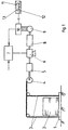
- a stack 2 of an feeder or delivery arm of a sheet-fed offset printing machine, not shown, located on a stack support plate 1 can be moved vertically via chains 3 connected to the stack support plate 1.
- the chains 3 are operatively connected to a drivable sprocket shaft 4, which is coupled to a motor 6 via a gear 5.
- the motor 6 is also assigned an electrically releasable brake, which is not shown in the figure, and in particular manages that when the power is switched off or other emergency or dangerous situations, the stack support plate 1 can be locked in the respective position.
- the reduction of the reduction gear 8 for coupling the angle encoder 9 is such that the entire travel of the stack support plate 1, especially between the floor and a maximum attainable upper position within a feeder or boom, does not quite cause one revolution of the rotor of the angle encoder 9.
- a movement of the stack support plate 1 between the floor indicated in the figure and a maximum attainable upper position means that the digital values of the angle encoder always assume different values and the positions of the stack support plate 1 clearly represent values.
- the angle encoder 9 is direct via the reduction gear connected to the shaft of the motor 6.
- the reduction gear 8 can also be attached to the gear 5 of the sprocket shaft 4 or to the sprocket shaft 4. It is decisive according to the invention that the entire travel path of the stack support plate 1 produces less than one revolution of the angle encoder 9 or that the entire travel path of the stack support plate 1 is mapped to an area ⁇ 360 ° of the rotor of the angle transmitter 9.
- the angle encoder 9 is designed as an absolute angle encoder, ie corresponding digital signals can be taken from it on a number of lines supplying binary signals or in the form of a serial data stream directly after switching on the devices, the rotor position (encoder disk) of the latter.
- the angle transmitter 9 is connected to a downstream evaluation unit 10, via which the current vertical position of the stack support plate 1 within the feeder or delivery arm can be determined after input of a reference value.
- the input reference value is assigned to the digital angle value currently present when the input is made, so that all positions (positions) of the stack support plate 1 in the feeder / delivery arm can now be determined and approached by specifying a digital angle value.
- the evaluation unit 10 by means of which the digital signals of the angle encoder 9 are converted in accordance with the information given above, is operatively connected to a controller 7, by means of which the energization of the motor 6 is in accordance with the signals of the angle encoder 9 or its values converted via the evaluation unit 10 to move to predetermined positions of the stack support plate 1.
- these traversing processes can be carried out by manual operating commands or also programmed.
- the controller 7 is not only able to carry out a position control for moving to predetermined positions, but also to control the speed of the travel process, which can be determined from a signal of the angle encoder 9, in order to maintain predetermined speed values.
- the controller 7 is in operative connection with a controller, not shown, of the printing press, which is indicated in FIG. 1 (arrow).
- the control 7 of the motor 6 can also be used to control other drive elements of the feeder or boom, which are not yet shown.
- an input device 11 in the form of a handheld terminal or laptop with keyboard 12 and a display device 13 (display) can be connected to the evaluation unit 10 connected downstream of the angle encoder 9. This is done via a standardized interface, which is accessible in the area of the feeder or the delivery arm. This interface (plug connection) can also be attached to a bus belonging to the control of the printing press, the evaluation unit 10 of the angle transmitter 9 being connected to this bus system (not shown in FIG. 1).
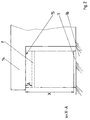
- Fig. 2 shows in principle a cantilever 14 of an offset printing machine, not shown.
- the stack support plate 1 rests on the floor 16.
- the distance X between the upper edge of the stacking support plate 1 and the lower edge of the cantilever 14 marked with the reference mark 15 is measured by means of a measuring tape or a scale.
- dimension A represents the distance from the lower edge 15 of the boom 14 to the uppermost position of the stacking support plate 1 ′, shown in broken lines in FIG. 2.
- the size x XA is thus the distance of the current position of the stack support plate 1 from the maximum upper position within the boom 14.
- the value x obtained in accordance with the information given above is then fed via the input device 11 to the evaluation unit 10, whereupon the latter enters the measured value of the current detectable angular position of the Assigned angle encoder 9 and converted accordingly for the further positioning processes.
Landscapes
- Engineering & Computer Science (AREA)
- Mechanical Engineering (AREA)
- Controlling Sheets Or Webs (AREA)
- Sheets, Magazines, And Separation Thereof (AREA)
- Pile Receivers (AREA)
Applications Claiming Priority (2)
| Application Number | Priority Date | Filing Date | Title |
|---|---|---|---|
| DE19613290 | 1996-04-03 | ||
| DE19613290A DE19613290C1 (de) | 1996-04-03 | 1996-04-03 | Steuerung für den Stapelhubantrieb einer bogenverarbeitenden Maschine |
Publications (3)
| Publication Number | Publication Date |
|---|---|
| EP0799785A2 true EP0799785A2 (fr) | 1997-10-08 |
| EP0799785A3 EP0799785A3 (fr) | 1998-01-28 |
| EP0799785B1 EP0799785B1 (fr) | 2000-07-19 |
Family
ID=7790346
Family Applications (1)
| Application Number | Title | Priority Date | Filing Date |
|---|---|---|---|
| EP97104474A Expired - Lifetime EP0799785B1 (fr) | 1996-04-03 | 1997-03-15 | Commande pour l'entraínement de levage de piles d'une machine de traitement de feuilles |
Country Status (4)
| Country | Link |
|---|---|
| EP (1) | EP0799785B1 (fr) |
| JP (1) | JP2804260B2 (fr) |
| AT (1) | ATE194811T1 (fr) |
| DE (2) | DE19613290C1 (fr) |
Cited By (1)
| Publication number | Priority date | Publication date | Assignee | Title |
|---|---|---|---|---|
| EP0799783A3 (fr) * | 1996-04-03 | 1998-01-28 | MAN Roland Druckmaschinen AG | Dispositif pour contrÔler le moteur de l'élévateur de pile d'une machine à imprimer des feuilles |
Families Citing this family (2)
| Publication number | Priority date | Publication date | Assignee | Title |
|---|---|---|---|---|
| DE10242255C5 (de) * | 2001-10-10 | 2011-06-09 | Heidelberger Druckmaschinen Ag | Flächige Bedruckstoffe verarbeitende Maschine |
| DE10322435B3 (de) * | 2003-05-19 | 2004-06-17 | Man Roland Druckmaschinen Ag | Stapelhubantrieb für eine Bogen verarbeitende Maschine |
Family Cites Families (8)
| Publication number | Priority date | Publication date | Assignee | Title |
|---|---|---|---|---|
| US4228396A (en) * | 1978-05-26 | 1980-10-14 | Dataproducts Corporation | Electronic tachometer and combined brushless motor commutation and tachometer system |
| US4535463A (en) * | 1981-10-13 | 1985-08-13 | Minolta Camera Co., Ltd. | Apparatus for detecting number of remaining sheets |
| DE3140795C2 (de) * | 1981-10-14 | 1985-03-21 | Jungheinrich Unternehmensverwaltung Kg, 2000 Hamburg | Höhenmeßeinrichtung für Stapelgeräte |
| DE3618728A1 (de) * | 1985-06-04 | 1986-12-04 | Ricoh Co., Ltd., Tokio/Tokyo | Steuerungseinrichtung fuer die papierzufuehrung in einem kopiergeraet |
| JP2595828B2 (ja) * | 1991-04-22 | 1997-04-02 | 株式会社日立製作所 | エレベーター装置 |
| DE4207305C2 (de) * | 1992-03-07 | 1996-09-19 | Heidelberger Druckmasch Ag | Vorrichtung zur Steuerung des Stapelträgers in Druckmaschinen |
| DE19613288C2 (de) * | 1996-04-03 | 1999-06-17 | Roland Man Druckmasch | Steuerung für den Stapelhubantrieb einer bogenverarbeitenden Maschine |
| DE19613287C2 (de) * | 1996-04-03 | 1999-03-04 | Roland Man Druckmasch | Stapelhubantrieb für eine bogenverarbeitende Maschine |
-
1996
- 1996-04-03 DE DE19613290A patent/DE19613290C1/de not_active Expired - Fee Related
-
1997
- 1997-03-15 DE DE59702036T patent/DE59702036D1/de not_active Expired - Fee Related
- 1997-03-15 EP EP97104474A patent/EP0799785B1/fr not_active Expired - Lifetime
- 1997-03-15 AT AT97104474T patent/ATE194811T1/de not_active IP Right Cessation
- 1997-04-03 JP JP9085326A patent/JP2804260B2/ja not_active Expired - Fee Related
Cited By (1)
| Publication number | Priority date | Publication date | Assignee | Title |
|---|---|---|---|---|
| EP0799783A3 (fr) * | 1996-04-03 | 1998-01-28 | MAN Roland Druckmaschinen AG | Dispositif pour contrÔler le moteur de l'élévateur de pile d'une machine à imprimer des feuilles |
Also Published As
| Publication number | Publication date |
|---|---|
| JP2804260B2 (ja) | 1998-09-24 |
| ATE194811T1 (de) | 2000-08-15 |
| EP0799785A3 (fr) | 1998-01-28 |
| EP0799785B1 (fr) | 2000-07-19 |
| JPH1053343A (ja) | 1998-02-24 |
| DE19613290C1 (de) | 1997-06-05 |
| DE59702036D1 (de) | 2000-08-24 |
Similar Documents
| Publication | Publication Date | Title |
|---|---|---|
| DE102007057455B4 (de) | Druckmaschine mit Druckplattenmanipulationseinrichtung | |
| EP3515849B1 (fr) | Procédé et dispositif d'enlèvement d'un rouleau de bande de matériau d'un support de rouleau, presse rotative ainsi que dispositif de surveillance d'un état de charge | |
| EP4017826B1 (fr) | Unité de commande et procédé d'actionnement d'un moyen de transport | |
| DE69204410T2 (de) | Vorrichtung und Verfahren zum Zuführen vorgearbeiteter Teilen zu einer Formvorrichtung, insbesondere zu einer Presse. | |
| DE19613288C2 (de) | Steuerung für den Stapelhubantrieb einer bogenverarbeitenden Maschine | |
| DE3541277A1 (de) | Steuervorrichtung fuer einen druckmaschinenantriebsmotor oder dergleichen | |
| AT503916A4 (de) | Vereinzelungsvorrichtung | |
| EP0799784B1 (fr) | Entraínement de levage de piles pour une machine de traitement de feuilles | |
| EP0799785A2 (fr) | Commande pour l'entraînement de levage de piles d'une machine de traitement de feuilles | |
| DE10054792A1 (de) | Flurförderzeug mit einer Vorrichtung zum Erfassen der Hubhöhe | |
| DE4207305C2 (de) | Vorrichtung zur Steuerung des Stapelträgers in Druckmaschinen | |
| EP3895301A1 (fr) | Dispositif équipé d'un moteur électrique pour la mise à disposition de matériau d'emballage et procédé pour faire fonctionner un dispositif de mise à disposition de matériau d'emballage | |
| DE102004002307A1 (de) | Verfahren zur Synchronisation von Haupt- und Hilfsstapel | |
| DE102006062980B3 (de) | Detektor zur Schließpunkterfassung im Farbkasten | |
| DE2226118A1 (de) | Steuervorrichtung für einen Metallband-Vorschub | |
| AT501792B1 (de) | Überlastsicherung in einem stapelhubwerk | |
| EP0894755A1 (fr) | Dispositif de positionnement pour un changeur automatique de pile | |
| DE10330579C5 (de) | Vorrichtung zum Regeln der Weite des Farbspaltes bei einer Druckmaschine | |
| DE102006054006B4 (de) | Verschleißdetektor für Farbkastenfolien | |
| EP1002751B1 (fr) | Dispositif pour le positionnement de supports de piles dans le margeur ou le dispositif de sortie d'une machine à imprimer des feuilles | |
| EP4403300A1 (fr) | Ensemble d'appareils, installation, fonctionnement automatisé de machines et procédé de chargement et de déchargement d'une machine de traitement | |
| EP1036659B1 (fr) | Dispositif pour commander des organes de réglage d'une machine à imprimer par ajustage à distance | |
| DE102005018890A1 (de) | Sicherheitseinrichtung in bedruckstoffverarbeitenden Maschinen | |
| EP2033919B1 (fr) | Machine à imprimer dotée d'une protection électrique contre l'écrasement | |
| CH654780A5 (en) | Apparatus for advancing and withdrawing units to be exchanged of a machine |
Legal Events
| Date | Code | Title | Description |
|---|---|---|---|
| PUAI | Public reference made under article 153(3) epc to a published international application that has entered the european phase |
Free format text: ORIGINAL CODE: 0009012 |
|
| 17P | Request for examination filed |
Effective date: 19970326 |
|
| AK | Designated contracting states |
Kind code of ref document: A2 Designated state(s): AT CH DE FR GB IT LI NL |
|
| PUAL | Search report despatched |
Free format text: ORIGINAL CODE: 0009013 |
|
| AK | Designated contracting states |
Kind code of ref document: A3 Designated state(s): AT CH DE FR GB IT LI NL |
|
| 17Q | First examination report despatched |
Effective date: 19980915 |
|
| GRAG | Despatch of communication of intention to grant |
Free format text: ORIGINAL CODE: EPIDOS AGRA |
|
| GRAG | Despatch of communication of intention to grant |
Free format text: ORIGINAL CODE: EPIDOS AGRA |
|
| GRAH | Despatch of communication of intention to grant a patent |
Free format text: ORIGINAL CODE: EPIDOS IGRA |
|
| GRAH | Despatch of communication of intention to grant a patent |
Free format text: ORIGINAL CODE: EPIDOS IGRA |
|
| ITF | It: translation for a ep patent filed | ||
| GRAA | (expected) grant |
Free format text: ORIGINAL CODE: 0009210 |
|
| AK | Designated contracting states |
Kind code of ref document: B1 Designated state(s): AT CH DE FR GB IT LI NL |
|
| REF | Corresponds to: |
Ref document number: 194811 Country of ref document: AT Date of ref document: 20000815 Kind code of ref document: T |
|
| ET | Fr: translation filed | ||
| REG | Reference to a national code |
Ref country code: CH Ref legal event code: NV Representative=s name: E. BLUM & CO. PATENTANWAELTE Ref country code: CH Ref legal event code: EP |
|
| GBT | Gb: translation of ep patent filed (gb section 77(6)(a)/1977) |
Effective date: 20000719 |
|
| REF | Corresponds to: |
Ref document number: 59702036 Country of ref document: DE Date of ref document: 20000824 |
|
| PLBE | No opposition filed within time limit |
Free format text: ORIGINAL CODE: 0009261 |
|
| STAA | Information on the status of an ep patent application or granted ep patent |
Free format text: STATUS: NO OPPOSITION FILED WITHIN TIME LIMIT |
|
| 26N | No opposition filed | ||
| REG | Reference to a national code |
Ref country code: GB Ref legal event code: IF02 |
|
| PGFP | Annual fee paid to national office [announced via postgrant information from national office to epo] |
Ref country code: CH Payment date: 20030218 Year of fee payment: 7 |
|
| PGFP | Annual fee paid to national office [announced via postgrant information from national office to epo] |
Ref country code: GB Payment date: 20030226 Year of fee payment: 7 |
|
| PGFP | Annual fee paid to national office [announced via postgrant information from national office to epo] |
Ref country code: NL Payment date: 20030228 Year of fee payment: 7 |
|
| PGFP | Annual fee paid to national office [announced via postgrant information from national office to epo] |
Ref country code: FR Payment date: 20030314 Year of fee payment: 7 |
|
| PG25 | Lapsed in a contracting state [announced via postgrant information from national office to epo] |
Ref country code: GB Free format text: LAPSE BECAUSE OF NON-PAYMENT OF DUE FEES Effective date: 20040315 |
|
| PG25 | Lapsed in a contracting state [announced via postgrant information from national office to epo] |
Ref country code: LI Free format text: LAPSE BECAUSE OF NON-PAYMENT OF DUE FEES Effective date: 20040331 Ref country code: CH Free format text: LAPSE BECAUSE OF NON-PAYMENT OF DUE FEES Effective date: 20040331 |
|
| PG25 | Lapsed in a contracting state [announced via postgrant information from national office to epo] |
Ref country code: NL Free format text: LAPSE BECAUSE OF NON-PAYMENT OF DUE FEES Effective date: 20041001 |
|
| GBPC | Gb: european patent ceased through non-payment of renewal fee |
Effective date: 20040315 |
|
| REG | Reference to a national code |
Ref country code: CH Ref legal event code: PL |
|
| PG25 | Lapsed in a contracting state [announced via postgrant information from national office to epo] |
Ref country code: FR Free format text: LAPSE BECAUSE OF NON-PAYMENT OF DUE FEES Effective date: 20041130 |
|
| NLV4 | Nl: lapsed or anulled due to non-payment of the annual fee |
Effective date: 20041001 |
|
| REG | Reference to a national code |
Ref country code: FR Ref legal event code: ST |
|
| PGFP | Annual fee paid to national office [announced via postgrant information from national office to epo] |
Ref country code: AT Payment date: 20050311 Year of fee payment: 9 |
|
| PG25 | Lapsed in a contracting state [announced via postgrant information from national office to epo] |
Ref country code: IT Free format text: LAPSE BECAUSE OF NON-PAYMENT OF DUE FEES;WARNING: LAPSES OF ITALIAN PATENTS WITH EFFECTIVE DATE BEFORE 2007 MAY HAVE OCCURRED AT ANY TIME BEFORE 2007. THE CORRECT EFFECTIVE DATE MAY BE DIFFERENT FROM THE ONE RECORDED. Effective date: 20050315 |
|
| PG25 | Lapsed in a contracting state [announced via postgrant information from national office to epo] |
Ref country code: AT Free format text: LAPSE BECAUSE OF NON-PAYMENT OF DUE FEES Effective date: 20060315 |
|
| PGFP | Annual fee paid to national office [announced via postgrant information from national office to epo] |
Ref country code: DE Payment date: 20070316 Year of fee payment: 11 |
|
| PG25 | Lapsed in a contracting state [announced via postgrant information from national office to epo] |
Ref country code: DE Free format text: LAPSE BECAUSE OF NON-PAYMENT OF DUE FEES Effective date: 20081001 |