EP0799998B1 - Pompe à piston rotatif avec des moyens de retenue magnétiques - Google Patents
Pompe à piston rotatif avec des moyens de retenue magnétiques Download PDFInfo
- Publication number
- EP0799998B1 EP0799998B1 EP97104154A EP97104154A EP0799998B1 EP 0799998 B1 EP0799998 B1 EP 0799998B1 EP 97104154 A EP97104154 A EP 97104154A EP 97104154 A EP97104154 A EP 97104154A EP 0799998 B1 EP0799998 B1 EP 0799998B1
- Authority
- EP
- European Patent Office
- Prior art keywords
- pump
- magnet
- rotor
- magnets
- drive shaft
- Prior art date
- Legal status (The legal status is an assumption and is not a legal conclusion. Google has not performed a legal analysis and makes no representation as to the accuracy of the status listed.)
- Expired - Lifetime
Links
- 238000006073 displacement reaction Methods 0.000 claims description 4
- 239000000463 material Substances 0.000 claims description 4
- 238000005086 pumping Methods 0.000 claims 2
- 230000000717 retained effect Effects 0.000 claims 1
- XEEYBQQBJWHFJM-UHFFFAOYSA-N Iron Chemical compound [Fe] XEEYBQQBJWHFJM-UHFFFAOYSA-N 0.000 abstract description 4
- 229910052742 iron Inorganic materials 0.000 abstract description 2
- 238000007789 sealing Methods 0.000 description 4
- 238000004140 cleaning Methods 0.000 description 2
- 230000000694 effects Effects 0.000 description 2
- 238000012423 maintenance Methods 0.000 description 2
- 244000052616 bacterial pathogen Species 0.000 description 1
- 230000015572 biosynthetic process Effects 0.000 description 1
- 238000009395 breeding Methods 0.000 description 1
- 230000001488 breeding effect Effects 0.000 description 1
- 238000010438 heat treatment Methods 0.000 description 1
- 239000012535 impurity Substances 0.000 description 1
- 238000004519 manufacturing process Methods 0.000 description 1
- 238000010327 methods by industry Methods 0.000 description 1
Images


Classifications
-
- F—MECHANICAL ENGINEERING; LIGHTING; HEATING; WEAPONS; BLASTING
- F04—POSITIVE - DISPLACEMENT MACHINES FOR LIQUIDS; PUMPS FOR LIQUIDS OR ELASTIC FLUIDS
- F04C—ROTARY-PISTON, OR OSCILLATING-PISTON, POSITIVE-DISPLACEMENT MACHINES FOR LIQUIDS; ROTARY-PISTON, OR OSCILLATING-PISTON, POSITIVE-DISPLACEMENT PUMPS
- F04C15/00—Component parts, details or accessories of machines, pumps or pumping installations, not provided for in groups F04C2/00 - F04C14/00
- F04C15/0057—Driving elements, brakes, couplings, transmission specially adapted for machines or pumps
- F04C15/0061—Means for transmitting movement from the prime mover to driven parts of the pump, e.g. clutches, couplings, transmissions
- F04C15/0073—Couplings between rotors and input or output shafts acting by interengaging or mating parts, i.e. positive coupling of rotor and shaft
-
- F—MECHANICAL ENGINEERING; LIGHTING; HEATING; WEAPONS; BLASTING
- F04—POSITIVE - DISPLACEMENT MACHINES FOR LIQUIDS; PUMPS FOR LIQUIDS OR ELASTIC FLUIDS
- F04C—ROTARY-PISTON, OR OSCILLATING-PISTON, POSITIVE-DISPLACEMENT MACHINES FOR LIQUIDS; ROTARY-PISTON, OR OSCILLATING-PISTON, POSITIVE-DISPLACEMENT PUMPS
- F04C15/00—Component parts, details or accessories of machines, pumps or pumping installations, not provided for in groups F04C2/00 - F04C14/00
- F04C15/0042—Systems for the equilibration of forces acting on the machines or pump
-
- F—MECHANICAL ENGINEERING; LIGHTING; HEATING; WEAPONS; BLASTING
- F04—POSITIVE - DISPLACEMENT MACHINES FOR LIQUIDS; PUMPS FOR LIQUIDS OR ELASTIC FLUIDS
- F04C—ROTARY-PISTON, OR OSCILLATING-PISTON, POSITIVE-DISPLACEMENT MACHINES FOR LIQUIDS; ROTARY-PISTON, OR OSCILLATING-PISTON, POSITIVE-DISPLACEMENT PUMPS
- F04C2230/00—Manufacture
- F04C2230/60—Assembly methods
-
- F—MECHANICAL ENGINEERING; LIGHTING; HEATING; WEAPONS; BLASTING
- F04—POSITIVE - DISPLACEMENT MACHINES FOR LIQUIDS; PUMPS FOR LIQUIDS OR ELASTIC FLUIDS
- F04C—ROTARY-PISTON, OR OSCILLATING-PISTON, POSITIVE-DISPLACEMENT MACHINES FOR LIQUIDS; ROTARY-PISTON, OR OSCILLATING-PISTON, POSITIVE-DISPLACEMENT PUMPS
- F04C2240/00—Components
- F04C2240/10—Stators
-
- F—MECHANICAL ENGINEERING; LIGHTING; HEATING; WEAPONS; BLASTING
- F04—POSITIVE - DISPLACEMENT MACHINES FOR LIQUIDS; PUMPS FOR LIQUIDS OR ELASTIC FLUIDS
- F04C—ROTARY-PISTON, OR OSCILLATING-PISTON, POSITIVE-DISPLACEMENT MACHINES FOR LIQUIDS; ROTARY-PISTON, OR OSCILLATING-PISTON, POSITIVE-DISPLACEMENT PUMPS
- F04C2240/00—Components
- F04C2240/20—Rotors
-
- Y—GENERAL TAGGING OF NEW TECHNOLOGICAL DEVELOPMENTS; GENERAL TAGGING OF CROSS-SECTIONAL TECHNOLOGIES SPANNING OVER SEVERAL SECTIONS OF THE IPC; TECHNICAL SUBJECTS COVERED BY FORMER USPC CROSS-REFERENCE ART COLLECTIONS [XRACs] AND DIGESTS
- Y10—TECHNICAL SUBJECTS COVERED BY FORMER USPC
- Y10S—TECHNICAL SUBJECTS COVERED BY FORMER USPC CROSS-REFERENCE ART COLLECTIONS [XRACs] AND DIGESTS
- Y10S403/00—Joints and connections
- Y10S403/01—Magnetic
Definitions
- the invention relates to a pump, in particular a Rotary lobe pump with at least one in a pump chamber rotating rotor, which protrudes into the pump chamber End of a drive shaft can be pushed.
- Rotary lobe pumps are characterized by the fact that they Conveying goods particularly gently. Besides, hers is Pump chamber easily accessible and can be after the Effectively clean the removal of the rotors. For these reasons Rotary lobe pumps meet high hygienic requirements and are preferred in the production of food, in pharmaceutical process engineering or in Biotechnology used.
- a disadvantage of the known holder is that the release and especially the assembly of the bracket is very complex. So a tool is necessary to loosen the screws and the bracket, the two encompassing the shaft and the sleeve Has half shells to remove. To be sufficient To allow good handling of the brackets must be sufficient there should be free space around the brackets. The distance between the pump chamber and the clutch housing large that a person’s hand fits in between. The cumbersome handling of the clip makes the maintenance and Cleaning work on the pump is relatively complex.
- the object of the invention is to provide a pump in particular To create a rotary lobe pump whose at least one rotor is easily removable from the drive shaft and whose pump chamber can be cleaned easily and thoroughly can.
- the object is achieved by a pump according to the Claim 1 solved.
- the rotors attached to the drive shaft is that the rotors after removing the front housing wall with a few Handles from the one that forms the rotor housing Pump chamber protruding ends of the drive shaft deducted can be made without the need for additional tools.
- the rotor of the Drive shaft pulled by the front housing wall with the magnet inside is turned over so that the magnet attracts the rotor.
- the assembly of a rotor a drive shaft is so comfortable that it too can be done mechanically.
- the holder according to the invention carries through the magnets also help to make the pump particularly compact can be because there is no separate space for handling the connection between the rotor and drive shaft is necessary.
- the magnetic forces can be from permanent magnets or generated by electromagnets.
- Permanent magnets have the advantage of being large magnetic Forces even without an additional electrical supply be available.
- the permanent magnets anywhere in the rotors or the housing parts to be built in. Electromagnets have the Advantage that the magnetic force on and off as required can be switched off. Removing the rotors at switched off magnet is particularly simple.
- the magnetic holder has the advantage that it all pump types, one on a drive shaft have attached rotor, is applicable.
- Rotary lobe pumps are a particularly advantageous axial one Bracket of the rotors (rotary pistons) on the drive shaft possible if the rotor or one connected to the rotor Part in particular a sleeve from the magnetic force is pressed against a stop.
- the attack is there advantageously an edge or a ring of the Surrounds the drive shaft.
- the easy handling of the front housing cover and the rotors becomes one convenient maintenance and cleaning of the pump chamber one Rotary lobe pump made possible in a few simple steps.
- the rotary lobe pump according to the invention has the advantage that none in the pump chamber except in the sealing hub There are gaps in which goods to be conveyed settle and to Can be a breeding ground for germs.
- the rotary lobe pump is a magnet ring-shaped around the end of the sleeve formed on the rotor arranged. This magnet works with an attractive force on an annular projection running around the shaft or a ring-shaped magnet.
- magnets are in the rear housing wall of the pump chamber facing surfaces of the rotor installed.
- magnets in the rear case wall to install which in particular put together into a ring are. This creates an even attractive force reached.
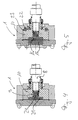
- FIGS. 1 to 5 each show a pump chamber 1 a rotary lobe pump.
- the pump chamber 1 has a housing 2, which is closed by a front housing wall 3 is.
- the front housing wall 3 is with screws 4 on Housing 2 attached and sealed with a seal 5.
- the housing 2 has a front housing wall 3 parallel rear housing wall 6.
- a sealing hub 7 trained bore through which a drive shaft 8 in the Pump chamber 1 is introduced.
- the summarize in the bore 11 of the rotary piston 10 located teeth in a Tooth profile 12, which is located on the end 9.
- the Hole 11 is not continuous.
- An axial extension is in shape on the rotary piston 10 molded on a sleeve 13 which surrounds the drive shaft 8 and which passes through the sealed hub 7.
- the seal 20, which surrounds the hub 7 is thus on the sleeve 13.
- the sleeve 13 abuts with a screwed-in edge 13a Stop 14 on, which surrounds the drive shaft 8 in a ring.
- the stop 14 limits the axial displacement of the Rotary piston 10 in the direction of the rear housing wall 6.
- In the inner wall of the sleeve 13 is screwed into a groove which is a sealing ring (O-ring) 20a. This o-ring 20a seals the sleeve 13 against the drive shaft 8, so that no impurities to the stop 14 forming radially aligned surface can reach.
- the axial displacement of the rotary piston in the direction the front housing wall 3 by magnetic forces caused by two magnets 15 and 16 become.
- the magnet 15 is in the front housing wall 3 installed, while the magnet 16 in the rotary piston 10 is installed behind a thin wall 17.
- the magnets 15 and 16 are poled so that they repel each other.
- the magnet 15 is in a blind hole 18 in the front housing wall 3 used which is closed with a lid 19.
- the repulsive force of the magnets also presses the rotary piston 10 the attached sleeve 13 against the stop 14, so that a Moving the rotary piston on the drive shaft 8 is impossible.
- the axial force of the magnets sufficient to close a mechanical seal.
- a magnet 21 installed in the rotary piston 10 such that it an attractive force on the end 9 of the drive shaft 8 from ferritic material in particular iron.
- the Distance between the end 9 and the magnet 21 is very small and is designed so that the attractive force in the expansion of the rotary piston 10 is easy to overcome.
- FIG 3 a pump chamber 1 is shown, the one Rotary piston 10, which of the magnets 22 in the rear housing wall 6 are installed is tightened. To the attracting force are also in the wings of the Rotary piston 10 magnets 23 installed, the corresponding are polarized in the same direction. The magnets 22 and 23 are arranged concentrically around the drive shaft 8.
- Figure 4 corresponds to that Figure 2 except for the fact that to support the attractive forces of the magnet 21 on the end 9 of the Drive shaft 10 an additional magnet 24 in the end 9 built-in. Both magnets 21 and 24 have the same polarity, so that an attractive force arises.
- the centrally located and the ring-shaped magnets are shaped so that there is no imbalance when the pump is running.
Landscapes
- Engineering & Computer Science (AREA)
- Mechanical Engineering (AREA)
- General Engineering & Computer Science (AREA)
- Details And Applications Of Rotary Liquid Pumps (AREA)
- Rotary Pumps (AREA)
- Vaporization, Distillation, Condensation, Sublimation, And Cold Traps (AREA)
Claims (11)
- Pompe, en particulier pompe à piston rotatif, avec au moins un rotor (10) tournant dans une chambre de pompe, qui est coulissant sur une extrémité (9), en saillie dans la chambre de pompe (1), d'un arbre d'entraínement (8),
caractérisée en ce qu'une force magnétique maintient à sa position axiale le rotor (10) ou une pièce reliée au rotor. - Pompe selon la revendication 1,
caractérisée en ce que la force magnétique pousse le rotor (10) ou la pièce reliée au rotor contre une butée (14) qui empêche une translation du rotor (10) sur l'arbre d'entraínement (8). - Pompe selon la revendication 1 ou 2,
caractérisée en ce qu'au moins un aimant permanent, qui agit sur un fer ferritique ou un autre aimant, engendre la force magnétique. - Pompe selon l'une des revendications précédentes,
caractérisée en ce qu'au moins un électro-aimant, qui agit sur un fer ferritique ou un autre aimant, engendre la force magnétique. - Pompe selon l'une des revendications précédentes,
caractérisée en ce que, sur le rotor (10), est monté un manchon (13) qui entoure l'arbre d'entraínement (8), un joint d'étanchéité, en particulier un joint d'étanchéité à anneau torique (20a), étant disposé entre le manchon (13) et l'arbre d'entraínement (8). - Pompe selon l'une des revendications précédentes,
caractérisée en ce que la pompe est une pompe à piston rotatif avec au moins deux rotors (10) réalisés sous forme de pistons rotatifs. - Pompe selon l'une des revendications précédentes,
caractérisée en ce qu'un aimant (15) est disposé dans la paroi de carter (3) antérieure et un aimant (16) dans la face frontale antérieure du piston rotatif tournée vers la paroi de carter (3) antérieure, les pôles des aimants (15, 16) étant dirigés de telle manière que les aimants se repoussent. - Pompe selon l'une des revendications précédentes,
caractérisée en ce que, dans le piston rotatif (10), est disposé un aimant (21) qui exerce sur l'extrémité antérieure (9) de l'arbre d'entraínement (8) une force attractive. - Pompe selon l'une des revendications précédentes,
caractérisée en ce que des aimants (23), qui exercent une force attractive sur la paroi de carter (6) arrière, sont disposés dans les ailettes du piston rotatif (10). - Pompe selon la revendication 9,
caractérisée en ce que des aimants (22), dont les pôles sont orientés de telle manière que les aimants exercent une force attractive sur les aimants (23) des ailettes, sont disposés dans la paroi de carter (6) arrière. - Pompe selon l'une des revendications précédentes,
caractérisée en ce qu'un aimant (21) est disposé dans le piston rotatif (10) et un aimant (24) dans l'extrémité antérieure (9) de l'arbre d'entraínement (8), les pôles des aimants (21, 24) étant orientés de telle manière que les aimants s'attirent.
Applications Claiming Priority (2)
| Application Number | Priority Date | Filing Date | Title |
|---|---|---|---|
| DE19613148A DE19613148A1 (de) | 1996-04-03 | 1996-04-03 | Drehkolbenpumpe mit magnetischer Rotorhalterung |
| DE19613148 | 1996-04-03 |
Publications (2)
| Publication Number | Publication Date |
|---|---|
| EP0799998A1 EP0799998A1 (fr) | 1997-10-08 |
| EP0799998B1 true EP0799998B1 (fr) | 1999-04-14 |
Family
ID=7790252
Family Applications (1)
| Application Number | Title | Priority Date | Filing Date |
|---|---|---|---|
| EP97104154A Expired - Lifetime EP0799998B1 (fr) | 1996-04-03 | 1997-03-12 | Pompe à piston rotatif avec des moyens de retenue magnétiques |
Country Status (4)
| Country | Link |
|---|---|
| US (1) | US5957677A (fr) |
| EP (1) | EP0799998B1 (fr) |
| AT (1) | ATE178976T1 (fr) |
| DE (2) | DE19613148A1 (fr) |
Families Citing this family (8)
| Publication number | Priority date | Publication date | Assignee | Title |
|---|---|---|---|---|
| DE19812976C2 (de) * | 1998-03-24 | 2000-05-04 | Siemens Ag | Flüssigkeitsringverdichter |
| RU2205980C2 (ru) * | 1999-08-27 | 2003-06-10 | Джеймс Б. ТАЙБЕН | Насос (варианты) |
| US6244842B1 (en) * | 1999-11-09 | 2001-06-12 | James B. Tieben | Pump |
| MXPA01004187A (es) * | 1999-08-27 | 2003-06-06 | B Tieben James | Bomba. |
| DE10024020A1 (de) * | 2000-05-16 | 2001-11-22 | Schlafhorst & Co W | Offenend-Spinnrotor |
| WO2013120483A1 (fr) | 2012-02-17 | 2013-08-22 | Netzsch Mohnopumpen Gmbh | Pompe à pistons rotatifs |
| US9500208B2 (en) * | 2014-04-25 | 2016-11-22 | Apple Inc. | Magnetic preloading of joints |
| CN111946613B (zh) * | 2020-08-25 | 2022-02-22 | 扬州大学 | 一种基于层流边界层和旋转磁场的微型圆盘泵设计方法 |
Family Cites Families (16)
| Publication number | Priority date | Publication date | Assignee | Title |
|---|---|---|---|---|
| DE1060482B (de) * | 1958-06-28 | 1959-07-02 | Gossen & Co Gmbh P | Einstellbare Innenlagerung fuer Kernmagnetmesswerke |
| US3080170A (en) * | 1959-01-02 | 1963-03-05 | Magnetic Seal Corp | Seal providing for substantial axial movement |
| DE2056661C3 (de) * | 1970-11-18 | 1975-03-27 | Eisenwerke Kaiserslautern Gmbh, 6750 Kaiserslautern | Verdrängerflügel für eine Drehkolbenpumpe zum Fördern zähflüssiger, gegebenenfalls inhomogener, korrosiver Medien |
| DE2206237A1 (de) * | 1972-02-10 | 1973-08-23 | Skf Kugellagerfabriken Gmbh | Lagerung fuer schnellaufende wellen oder achsen |
| DE2337226A1 (de) * | 1973-07-21 | 1975-02-06 | Maschf Augsburg Nuernberg Ag | Vakuumpumpe mit einem im innenraum ihres gehaeuses gelagerten laeufer |
| GB8333929D0 (en) * | 1983-12-20 | 1984-02-01 | Ssp Pumps | Rotary pumps |
| DE8815196U1 (de) * | 1988-12-07 | 1989-02-16 | Lewitz, Reinwald, 3100 Celle | Schwebe-Dreh-Flasche |
| NL9000785A (nl) * | 1990-04-03 | 1991-11-01 | Boer B V De | Verdringerpomp. |
| NL9001875A (nl) * | 1990-07-17 | 1992-02-17 | Bombas Stork S A | Lobbenrotorpomp. |
| DE4024067A1 (de) * | 1990-07-28 | 1992-01-30 | Friedhelm Schneider | Zahnradpumpe fuer hochviskose fluessigkeiten |
| JP2983325B2 (ja) * | 1991-04-26 | 1999-11-29 | 株式会社日本自動車部品総合研究所 | スクロール型圧縮機 |
| US5129795A (en) * | 1991-05-31 | 1992-07-14 | Powerdyne Corporation | Motor driven pump |
| US5350283A (en) * | 1991-12-04 | 1994-09-27 | Ntn Corporation | Clean pump |
| DE4224736A1 (de) * | 1992-07-27 | 1994-02-03 | Luk Fahrzeug Hydraulik | Hydraulikmaschine |
| US5391068A (en) * | 1994-02-15 | 1995-02-21 | Eaton Corporation | Gear pump |
| DE4410656A1 (de) * | 1994-03-26 | 1995-09-28 | Balzers Pfeiffer Gmbh | Reibungspumpe |
-
1996
- 1996-04-03 DE DE19613148A patent/DE19613148A1/de not_active Withdrawn
-
1997
- 1997-03-12 EP EP97104154A patent/EP0799998B1/fr not_active Expired - Lifetime
- 1997-03-12 DE DE59700129T patent/DE59700129D1/de not_active Expired - Lifetime
- 1997-03-12 AT AT97104154T patent/ATE178976T1/de not_active IP Right Cessation
- 1997-03-31 US US08/829,932 patent/US5957677A/en not_active Expired - Fee Related
Also Published As
| Publication number | Publication date |
|---|---|
| DE19613148A1 (de) | 1997-10-09 |
| ATE178976T1 (de) | 1999-04-15 |
| DE59700129D1 (de) | 1999-05-20 |
| US5957677A (en) | 1999-09-28 |
| EP0799998A1 (fr) | 1997-10-08 |
Similar Documents
| Publication | Publication Date | Title |
|---|---|---|
| DE3331245C2 (fr) | ||
| DE2337226A1 (de) | Vakuumpumpe mit einem im innenraum ihres gehaeuses gelagerten laeufer | |
| EP0799998B1 (fr) | Pompe à piston rotatif avec des moyens de retenue magnétiques | |
| DE3420898A1 (de) | Freistehender kanister-aquarienfilter | |
| EP3289221A1 (fr) | Pompe à fluide | |
| DE69304447T2 (de) | Drehkolbenpumpe | |
| DE3204534C2 (de) | Elektromagnetisch betätigte Membranpumpe | |
| DE2035380A1 (de) | Staubsauger mit einem von einem Elektro motor angetriebenen Sauggeblase | |
| DE60313493T2 (de) | Vakuumpumpe | |
| DE3220614C2 (fr) | ||
| DE3927391A1 (de) | Vorrichtung zum beheizen des fahrgastraumes eines kraftfahrzeuges | |
| DE8536175U1 (de) | Flüssigkeitsgekühlter Elektromotor | |
| DE4222264C2 (de) | Kühlvorrichtung für ein Kraftfahrzeug | |
| DE4110488A1 (de) | Magnetkupplung | |
| DE19755537A1 (de) | Transportsicherung für einen Motorbausatz eines kollektorlosen Gleichstrommotors als Außenläufermotor | |
| EP3299627B1 (fr) | Pompe d'alimentation | |
| EP0793871A1 (fr) | Stator de moteur monte amovible sur le flasque d'un element cupuliforme a fente | |
| DE514444C (de) | Vorrichtung zur Befestigung eines drehbaren Poliermittels an einem Staubsauger | |
| DE8700115U1 (de) | Elektromagnetische Kupplung | |
| DE4123551A1 (de) | Ueberlappungsrotationspumpe | |
| EP0844723A2 (fr) | Pompe entraínée par un moteur électrique | |
| DE444482C (de) | Aus Elektromotor und mehrstufiger Luftfoerdervorrichtung bestehender Maschinensatz, im besonderen fuer elektrische Handstaubsauger | |
| DE60109577T2 (de) | Tangentielle Lüftungsvorrichtung | |
| EP1411246A2 (fr) | Pompe à engrènement interne avec une couronne de train planetaire et un pignon interactif | |
| EP3657649A1 (fr) | Unité rotative électrique |
Legal Events
| Date | Code | Title | Description |
|---|---|---|---|
| PUAI | Public reference made under article 153(3) epc to a published international application that has entered the european phase |
Free format text: ORIGINAL CODE: 0009012 |
|
| AK | Designated contracting states |
Kind code of ref document: A1 Designated state(s): AT BE CH DE DK ES FR GB IE IT LI NL SE |
|
| 17P | Request for examination filed |
Effective date: 19971002 |
|
| GRAG | Despatch of communication of intention to grant |
Free format text: ORIGINAL CODE: EPIDOS AGRA |
|
| 17Q | First examination report despatched |
Effective date: 19981118 |
|
| GRAG | Despatch of communication of intention to grant |
Free format text: ORIGINAL CODE: EPIDOS AGRA |
|
| GRAH | Despatch of communication of intention to grant a patent |
Free format text: ORIGINAL CODE: EPIDOS IGRA |
|
| GRAH | Despatch of communication of intention to grant a patent |
Free format text: ORIGINAL CODE: EPIDOS IGRA |
|
| GRAA | (expected) grant |
Free format text: ORIGINAL CODE: 0009210 |
|
| AK | Designated contracting states |
Kind code of ref document: B1 Designated state(s): AT BE CH DE DK ES FR GB IE IT LI NL SE |
|
| PG25 | Lapsed in a contracting state [announced via postgrant information from national office to epo] |
Ref country code: SE Free format text: THE PATENT HAS BEEN ANNULLED BY A DECISION OF A NATIONAL AUTHORITY Effective date: 19990414 Ref country code: NL Free format text: LAPSE BECAUSE OF FAILURE TO SUBMIT A TRANSLATION OF THE DESCRIPTION OR TO PAY THE FEE WITHIN THE PRESCRIBED TIME-LIMIT Effective date: 19990414 Ref country code: IT Free format text: LAPSE BECAUSE OF FAILURE TO SUBMIT A TRANSLATION OF THE DESCRIPTION OR TO PAY THE FEE WITHIN THE PRE;WARNING: LAPSES OF ITALIAN PATENTS WITH EFFECTIVE DATE BEFORE 2007 MAY HAVE OCCURRED AT ANY TIME BEFORE 2007. THE CORRECT EFFECTIVE DATE MAY BE DIFFERENT FROM THE ONE RECORDED.SCRIBED TIME-LIMIT Effective date: 19990414 Ref country code: GB Free format text: LAPSE BECAUSE OF NON-PAYMENT OF DUE FEES Effective date: 19990414 Ref country code: FR Free format text: LAPSE BECAUSE OF FAILURE TO SUBMIT A TRANSLATION OF THE DESCRIPTION OR TO PAY THE FEE WITHIN THE PRESCRIBED TIME-LIMIT Effective date: 19990414 Ref country code: ES Free format text: THE PATENT HAS BEEN ANNULLED BY A DECISION OF A NATIONAL AUTHORITY Effective date: 19990414 |
|
| REF | Corresponds to: |
Ref document number: 178976 Country of ref document: AT Date of ref document: 19990415 Kind code of ref document: T |
|
| REG | Reference to a national code |
Ref country code: CH Ref legal event code: EP |
|
| REG | Reference to a national code |
Ref country code: IE Ref legal event code: FG4D Free format text: GERMAN |
|
| REF | Corresponds to: |
Ref document number: 59700129 Country of ref document: DE Date of ref document: 19990520 |
|
| PG25 | Lapsed in a contracting state [announced via postgrant information from national office to epo] |
Ref country code: DK Free format text: LAPSE BECAUSE OF FAILURE TO SUBMIT A TRANSLATION OF THE DESCRIPTION OR TO PAY THE FEE WITHIN THE PRESCRIBED TIME-LIMIT Effective date: 19990714 |
|
| NLV1 | Nl: lapsed or annulled due to failure to fulfill the requirements of art. 29p and 29m of the patents act | ||
| EN | Fr: translation not filed | ||
| GBV | Gb: ep patent (uk) treated as always having been void in accordance with gb section 77(7)/1977 [no translation filed] |
Effective date: 19990414 |
|
| PG25 | Lapsed in a contracting state [announced via postgrant information from national office to epo] |
Ref country code: IE Free format text: LAPSE BECAUSE OF NON-PAYMENT OF DUE FEES Effective date: 19991206 |
|
| REG | Reference to a national code |
Ref country code: IE Ref legal event code: FD4D |
|
| PLBE | No opposition filed within time limit |
Free format text: ORIGINAL CODE: 0009261 |
|
| STAA | Information on the status of an ep patent application or granted ep patent |
Free format text: STATUS: NO OPPOSITION FILED WITHIN TIME LIMIT |
|
| PG25 | Lapsed in a contracting state [announced via postgrant information from national office to epo] |
Ref country code: AT Free format text: LAPSE BECAUSE OF NON-PAYMENT OF DUE FEES Effective date: 20000312 |
|
| PG25 | Lapsed in a contracting state [announced via postgrant information from national office to epo] |
Ref country code: BE Free format text: LAPSE BECAUSE OF NON-PAYMENT OF DUE FEES Effective date: 20000331 |
|
| 26N | No opposition filed | ||
| BERE | Be: lapsed |
Owner name: ALFA LAVAL FLOW G.M.B.H. Effective date: 20000331 |
|
| PG25 | Lapsed in a contracting state [announced via postgrant information from national office to epo] |
Ref country code: LI Free format text: LAPSE BECAUSE OF NON-PAYMENT OF DUE FEES Effective date: 20010331 Ref country code: CH Free format text: LAPSE BECAUSE OF NON-PAYMENT OF DUE FEES Effective date: 20010331 |
|
| REG | Reference to a national code |
Ref country code: CH Ref legal event code: PL |
|
| PGFP | Annual fee paid to national office [announced via postgrant information from national office to epo] |
Ref country code: DE Payment date: 20100318 Year of fee payment: 14 |
|
| PG25 | Lapsed in a contracting state [announced via postgrant information from national office to epo] |
Ref country code: DE Free format text: LAPSE BECAUSE OF NON-PAYMENT OF DUE FEES Effective date: 20111001 |
|
| REG | Reference to a national code |
Ref country code: DE Ref legal event code: R119 Ref document number: 59700129 Country of ref document: DE Effective date: 20111001 |