EP0800007A2 - Arbre de transmission comprenant un tube en matière plastique renforcée et un élément d'accouplement lié d'une manière rigide à l'extrémité du tube - Google Patents
Arbre de transmission comprenant un tube en matière plastique renforcée et un élément d'accouplement lié d'une manière rigide à l'extrémité du tube Download PDFInfo
- Publication number
- EP0800007A2 EP0800007A2 EP97102187A EP97102187A EP0800007A2 EP 0800007 A2 EP0800007 A2 EP 0800007A2 EP 97102187 A EP97102187 A EP 97102187A EP 97102187 A EP97102187 A EP 97102187A EP 0800007 A2 EP0800007 A2 EP 0800007A2
- Authority
- EP
- European Patent Office
- Prior art keywords
- plastic tube
- profile
- plug pin
- fibers
- cardan shaft
- Prior art date
- Legal status (The legal status is an assumption and is not a legal conclusion. Google has not performed a legal analysis and makes no representation as to the accuracy of the status listed.)
- Withdrawn
Links
Images
Classifications
-
- F—MECHANICAL ENGINEERING; LIGHTING; HEATING; WEAPONS; BLASTING
- F16—ENGINEERING ELEMENTS AND UNITS; GENERAL MEASURES FOR PRODUCING AND MAINTAINING EFFECTIVE FUNCTIONING OF MACHINES OR INSTALLATIONS; THERMAL INSULATION IN GENERAL
- F16D—COUPLINGS FOR TRANSMITTING ROTATION; CLUTCHES; BRAKES
- F16D1/00—Couplings for rigidly connecting two coaxial shafts or other movable machine elements
- F16D1/06—Couplings for rigidly connecting two coaxial shafts or other movable machine elements for attachment of a member on a shaft or on a shaft-end
-
- F—MECHANICAL ENGINEERING; LIGHTING; HEATING; WEAPONS; BLASTING
- F16—ENGINEERING ELEMENTS AND UNITS; GENERAL MEASURES FOR PRODUCING AND MAINTAINING EFFECTIVE FUNCTIONING OF MACHINES OR INSTALLATIONS; THERMAL INSULATION IN GENERAL
- F16B—DEVICES FOR FASTENING OR SECURING CONSTRUCTIONAL ELEMENTS OR MACHINE PARTS TOGETHER, e.g. NAILS, BOLTS, CIRCLIPS, CLAMPS, CLIPS OR WEDGES; JOINTS OR JOINTING
- F16B21/00—Means for preventing relative axial movement of a pin, spigot, shaft or the like and a member surrounding it; Stud-and-socket releasable fastenings
- F16B21/10—Means for preventing relative axial movement of a pin, spigot, shaft or the like and a member surrounding it; Stud-and-socket releasable fastenings by separate parts
- F16B21/16—Means for preventing relative axial movement of a pin, spigot, shaft or the like and a member surrounding it; Stud-and-socket releasable fastenings by separate parts with grooves or notches in the pin or shaft
- F16B21/18—Means for preventing relative axial movement of a pin, spigot, shaft or the like and a member surrounding it; Stud-and-socket releasable fastenings by separate parts with grooves or notches in the pin or shaft with circlips or like resilient retaining devices, i.e. resilient in the plane of the ring or the like; Details
-
- F—MECHANICAL ENGINEERING; LIGHTING; HEATING; WEAPONS; BLASTING
- F16—ENGINEERING ELEMENTS AND UNITS; GENERAL MEASURES FOR PRODUCING AND MAINTAINING EFFECTIVE FUNCTIONING OF MACHINES OR INSTALLATIONS; THERMAL INSULATION IN GENERAL
- F16C—SHAFTS; FLEXIBLE SHAFTS; ELEMENTS OR CRANKSHAFT MECHANISMS; ROTARY BODIES OTHER THAN GEARING ELEMENTS; BEARINGS
- F16C3/00—Shafts; Axles; Cranks; Eccentrics
- F16C3/02—Shafts; Axles
- F16C3/026—Shafts made of fibre reinforced resin
-
- B—PERFORMING OPERATIONS; TRANSPORTING
- B29—WORKING OF PLASTICS; WORKING OF SUBSTANCES IN A PLASTIC STATE IN GENERAL
- B29K—INDEXING SCHEME ASSOCIATED WITH SUBCLASSES B29B, B29C OR B29D, RELATING TO MOULDING MATERIALS OR TO MATERIALS FOR MOULDS, REINFORCEMENTS, FILLERS OR PREFORMED PARTS, e.g. INSERTS
- B29K2105/00—Condition, form or state of moulded material or of the material to be shaped
- B29K2105/06—Condition, form or state of moulded material or of the material to be shaped containing reinforcements, fillers or inserts
- B29K2105/08—Condition, form or state of moulded material or of the material to be shaped containing reinforcements, fillers or inserts of continuous length, e.g. cords, rovings, mats, fabrics, strands or yarns
- B29K2105/10—Cords, strands or rovings, e.g. oriented cords, strands or rovings
- B29K2105/101—Oriented
- B29K2105/108—Oriented arranged in parallel planes and crossing at substantial angles
-
- F—MECHANICAL ENGINEERING; LIGHTING; HEATING; WEAPONS; BLASTING
- F16—ENGINEERING ELEMENTS AND UNITS; GENERAL MEASURES FOR PRODUCING AND MAINTAINING EFFECTIVE FUNCTIONING OF MACHINES OR INSTALLATIONS; THERMAL INSULATION IN GENERAL
- F16C—SHAFTS; FLEXIBLE SHAFTS; ELEMENTS OR CRANKSHAFT MECHANISMS; ROTARY BODIES OTHER THAN GEARING ELEMENTS; BEARINGS
- F16C2326/00—Articles relating to transporting
- F16C2326/01—Parts of vehicles in general
- F16C2326/06—Drive shafts
-
- F—MECHANICAL ENGINEERING; LIGHTING; HEATING; WEAPONS; BLASTING
- F16—ENGINEERING ELEMENTS AND UNITS; GENERAL MEASURES FOR PRODUCING AND MAINTAINING EFFECTIVE FUNCTIONING OF MACHINES OR INSTALLATIONS; THERMAL INSULATION IN GENERAL
- F16D—COUPLINGS FOR TRANSMITTING ROTATION; CLUTCHES; BRAKES
- F16D1/00—Couplings for rigidly connecting two coaxial shafts or other movable machine elements
- F16D1/10—Quick-acting couplings in which the parts are connected by simply bringing them together axially
- F16D1/108—Quick-acting couplings in which the parts are connected by simply bringing them together axially having retaining means rotating with the coupling and acting by interengaging parts, i.e. positive coupling
- F16D1/116—Quick-acting couplings in which the parts are connected by simply bringing them together axially having retaining means rotating with the coupling and acting by interengaging parts, i.e. positive coupling the interengaging parts including a continuous or interrupted circumferential groove in the surface of one of the coupling parts
-
- F—MECHANICAL ENGINEERING; LIGHTING; HEATING; WEAPONS; BLASTING
- F16—ENGINEERING ELEMENTS AND UNITS; GENERAL MEASURES FOR PRODUCING AND MAINTAINING EFFECTIVE FUNCTIONING OF MACHINES OR INSTALLATIONS; THERMAL INSULATION IN GENERAL
- F16D—COUPLINGS FOR TRANSMITTING ROTATION; CLUTCHES; BRAKES
- F16D1/00—Couplings for rigidly connecting two coaxial shafts or other movable machine elements
- F16D1/10—Quick-acting couplings in which the parts are connected by simply bringing them together axially
- F16D2001/103—Quick-acting couplings in which the parts are connected by simply bringing them together axially the torque is transmitted via splined connections
-
- F—MECHANICAL ENGINEERING; LIGHTING; HEATING; WEAPONS; BLASTING
- F16—ENGINEERING ELEMENTS AND UNITS; GENERAL MEASURES FOR PRODUCING AND MAINTAINING EFFECTIVE FUNCTIONING OF MACHINES OR INSTALLATIONS; THERMAL INSULATION IN GENERAL
- F16D—COUPLINGS FOR TRANSMITTING ROTATION; CLUTCHES; BRAKES
- F16D2200/00—Materials; Production methods therefor
- F16D2200/006—Materials; Production methods therefor containing fibres or particles
Definitions
- the invention is based on a propeller shaft according to the preamble of claim 1, as described, for example, in a publication in DE-Z ATZ Automobiltechnische Zeitschrift 96 (1994), pages 612 to 617, W. Hoffman et al. "The second generation of fiber composite cardan shafts" emerges as known. In an earlier volume of the same journal ATZ Automobiltechnische Zeitschrift 91 (1989), pages 149 to 152 by W. Hoffman published another article on the topic "Fiber composite material in the drive train", in which the "first generation” of fiber composite cardan shafts was published is reported.
- the drive shafts described have an endless fiber-reinforced plastic pipe of the same diameter over the entire length and - at least in the second generation - an articulated connector body made of short-fiber reinforced plastic, which is non-rotatably glued to the plastic pipe by means of a plug-in plug inserted into the plastic pipe.
- the circumference of the plug pin shown is provided with axially extending adhesive receiving grooves which are axially closed at the free end of the plug pin by a circumferential bead.
- EP 318 818 B1 In connection with the adhesive-related design of the connection point, reference can be made to EP 318 818 B1.
- the inner surface of the plastic tube is smooth due to the manufacturing process - the fibers are inclined at about 10 to 12 ° against the axial direction.
- the possible peak loads on the cardan shafts are determined by the adhesive connection and the maximum peak temperatures that occur during vehicle operation. The largest mentioned in the cited reference Load values are around 3300 Nm at room temperature and around 2900 Nm at 100 ° C
- shell parts which are grooved on the inside and which form a further sleeve are inserted between two adjacent individual layers in such a way that the grooves of the shell parts with the beads of the inner sleeve correspond to one another in terms of shape and position and deform the meandering between the two enclosed layers .
- This deformation merges into a cylindrical wall of the tube due to a profile on the sleeve or the shell parts that runs out toward the plastic tube.
- a disadvantage of this prior art is that the tubes have to be manufactured individually, which is not only cumbersome and too expensive for large-scale production, but also what makes different manufacturing facilities necessary for manufacturing different lengths of shafts. So this production is inefficient and non-universal.
- a composite shaft with integrated metal parts at the end also has the functional disadvantage that a stiffness jump due to the different strengths at the transition from the metal to the fiber-reinforced plastic and the various elasticity modules of the materials involved, which can lead to play in operation.
- the plug pin of the metal joint connection body is provided on the outer circumference with a fine axially aligned profile.
- the plug pin is pre-stressed into the plastic pipe, which has an undersize on the inside, with the sharp-edged profiling digging axially into the pipe wall and creating a pipe-side counter-profile itself.
- a bandage is applied to the pipe end, which prevents the pipe wall from expanding radially.
- this connection can be subjected to high static and dynamic loads even at elevated temperatures, this torsionally rigid connection can only be made laboriously on the one hand, and on the other hand there is an undesirable jump in stiffness between the pipe end and the joint connection body. This jump in stiffness would be omitted if the metal joint was replaced by an articulated connecting body, but the latter would loosen due to an unavoidable tendency of the plastic to creep under the pretension, particularly at elevated temperatures, so that such a cardan shaft would not be able to withstand loads.
- the object of the invention is to improve the generic drive shaft in such a way that it can be economically manufactured in large quantities and universally for different lengths of demand, but that it is also higher than the known drive shafts of comparable design even at temperatures above 140 ° C is resilient, so it also meets high functional requirements.
- an internal profile can be formed over the entire length of the tube during the manufacturing process, into which the plug pins of an articulated connecting body can be inserted in a form-fitting manner without any significant pretensioning.
- a continuous production process known per se namely the pulling / winding process, also called pull winding process, can be used - but does not have to - with which a quasi-endless plastic pipe can be produced in a rational manner with high productivity, from which any length of use can then be cut to length.
- the torque connection in the area of the pipe ends can withstand high loads even at elevated temperatures. Thanks to the sliding fit, but also with the slight press fit of the plug-in connection, no high permanent stresses occur and, consequently, no creep occurs, so that plastic can also be used on the side of the joint connector body without further notice. This can save considerable weight.
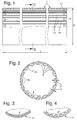
- the plastic tube 1 shown in FIG. 1 for a cardan shaft is reinforced with continuous fibers or continuous fiber strands - so-called rovings - 3 and 5, which are embedded in a thermosetting matrix material.
- the plastic tube has the same diameter D over its entire length L and, because of this, offers the geometric requirement to produce the tube in a rational, continuous, quasi-endless process according to the known pull-wrap or pull-winding process, which is not is only rational and cost-effective, but also creates the possibility of being able to produce any required length of plastic pipes without any significant conversion and investment costs. Different diameters of the plastic tube can also be produced after a certain, quickly accomplished changeover effort.
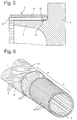
- the plastic tube 1 is connected in a rotationally fixed manner at its ends to an articulated connecting body 6, this torque connection being brought about by a plug pin 7 inserted into the plastic tube.
- the connection should be mechanically particularly high load even at elevated temperatures.
- the multilayer plastic tube 1 is provided on the one hand with an inner layer 2 with axially aligned fibers 3, on which at least one double layer 6 with fibers 5 arranged symmetrically to the axial direction at an angle ⁇ ⁇ is applied.
- the axially aligned fibers 3 increase the bending stiffness of the plastic tube, which is particularly important for the suitability of the cardan shaft for high speeds.
- the inclined fibers 5 give the plastic tube a high torsional stiffness required for torque transmission.
- a further double layer also called plus / minus position in technical jargon
- inclined fibers that is to say a total of two double layers with differently inclined fibers, in the plastic tube.
- the number of double layers and the required angle of inclination ⁇ ⁇ of the fibers within the double layers are selected or determined depending on the load data specified for the respective application according to customary design criteria.
- the entire length of the plastic tube is provided on the inside with an axially aligned, constant profile 8 in the manner of a spline profile, which consists of the matrix material and, if appropriate, axially aligned fibers or fiber strands embedded therein is formed.
- This profiling can be easily generated due to the process and does not require any special treatment of the pipe ends; the profiling is available at every axial position of the plastic pipe and allows any length of pipe to be produced.
- the plug 7 is on its outer circumference with a corresponding negative shape Provide counter-profiling 9, which positively engages in the inner profiling 8 of the plastic tube.
- the plug pin is fitted with a sliding fit or, if necessary, a light press fit with the profiling of the plastic tube.
- the selected fit between the spigot and the plastic tube must be selected so that, on the one hand, there is a good, ie play-free, centering between the parts to be joined, which avoids uncontrolled imbalances, but on the other hand there are no significant permanent stresses due to a tight fit that lead to creeping of the plastic Joining parts would lead.
- the joint connection body 6 is also made of plastic, namely of fiber-reinforced plastic.
- FIGS. 2, 3 or 4 Different cross-sectional shapes can be provided for the corresponding profiles 8 and 9, as shown in FIGS. 2, 3 or 4.
- the profiling 8 of the plastic tube 1 shown in FIG. 2 has - viewed in a developed stretch position - trapezoidal beads 13 and roughly similarly shaped grooves 14, which have a relatively large circumferential pitch, whereas the profiling 8 'of the tube 1' according to FIG. 3 by closely divided , triangular beads or grooves is determined. Viewed in cross section, both profile shapes have straight profile flanks.
- the further exemplary embodiment shown in FIG. 4 of a coarsely divided profiling 8 ′′ has convexly curved profile flanks in cross section.
- the profiling Based on the wall thickness 5 of the plastic tube measured at the deepest point of a groove 14, the profiling extends in the radial direction - dimension p - to about 33 to 100%. Based on the total wall thickness of the plastic tube measured over the beads 13, the radial height p of the profiling is approximately 25 to 50%.
- glass fibers, carbon fibers or aramid fibers can be used for the individual layers, these fiber materials can also be used mixed within one layer.
- the aim is to achieve a fiber volume fraction of 60 to 70%, in which such a fiber composite obtains its highest strength.
- Various curable synthetic resins are suitable as the matrix material, however, due to its favorable property profile, epoxy resin is used particularly frequently in connection with fiber-reinforced plastic pipes.
- the spigot in the plastic tube 1 is also secured in the axial direction, especially since the spigot is only fitted with a sliding fit or light press fit quality in the tube end.
- This axial securing can, for example, be effected mechanically by means of a snap-in connection shown in FIG. 5 by means of a spring snap ring 10 which engages in a circumferential groove 11 of both the plastic tube 1 and in a circumferential groove 12 of the plug-in pin.
- the plug-in groove 12 is with its inner diameter by at least the wire diameter smaller than the inner diameter of the spring snap ring 10 in the installed state, so that the spring snap ring can deflect radially inwards during installation.
- the spring snap ring Before assembling the joint body, the spring snap ring is inserted into the groove 12 and then the plug pin with its profile is inserted axially into the profile of the plastic tube.
- the beads 13 of the tube profiling are beveled on the end face and elastically press the spring snap ring radially inward when pushed in, as a result of which they "lift” it radially onto the inside of the beads 13.
- the ring 10 springs open again and mechanically locks the tube 1 and the plug pin 7 against axial pulling out.
- the axial securing can instead also be effected, for example, by gluing.
- a two-component adhesive the two components of which are applied in microencapsulated form to at least one of the contact surfaces, preferably to the plug pins.
- the microencapsulated two-component adhesive that has already been applied, for example, by the manufacturer of the joint connector body forms a dry, non-slip coating on the profile 9 of the plug pin, which has a certain mechanical resistance and storage stability and makes the joint connector body prepared for bonding transportable and manageable.
- the plug-in pin with its profile is pushed axially into the profile of the plastic tube with a certain amount of force. Due to the resulting shear stress on the adhesive application, the microcapsules are automatically destroyed, so that the two adhesive components mix when the plug is pushed in and the adhesive then sets.
- the axially securing adhesive is not claimed under the influence of torque and consequently does not need to meet the high quality demands to be made of a torque-transmitting adhesive between the joint connecting body and the plastic pipe.
Landscapes
- Engineering & Computer Science (AREA)
- General Engineering & Computer Science (AREA)
- Mechanical Engineering (AREA)
- Ocean & Marine Engineering (AREA)
- Shafts, Cranks, Connecting Bars, And Related Bearings (AREA)
Applications Claiming Priority (2)
| Application Number | Priority Date | Filing Date | Title |
|---|---|---|---|
| DE19613857 | 1996-04-06 | ||
| DE19613857A DE19613857C2 (de) | 1996-04-06 | 1996-04-06 | Gelenkwelle mit verstärktem Kunststoffrohr und mit einem endseitig drehfest verbundenen Gelenkanschlußkörper |
Publications (2)
| Publication Number | Publication Date |
|---|---|
| EP0800007A2 true EP0800007A2 (fr) | 1997-10-08 |
| EP0800007A3 EP0800007A3 (fr) | 1998-04-15 |
Family
ID=7790690
Family Applications (1)
| Application Number | Title | Priority Date | Filing Date |
|---|---|---|---|
| EP97102187A Withdrawn EP0800007A3 (fr) | 1996-04-06 | 1997-02-12 | Arbre de transmission comprenant un tube en matière plastique renforcée et un élément d'accouplement lié d'une manière rigide à l'extrémité du tube |
Country Status (4)
| Country | Link |
|---|---|
| US (1) | US5851152A (fr) |
| EP (1) | EP0800007A3 (fr) |
| JP (1) | JP3495553B2 (fr) |
| DE (1) | DE19613857C2 (fr) |
Cited By (4)
| Publication number | Priority date | Publication date | Assignee | Title |
|---|---|---|---|---|
| US5851152A (en) * | 1996-04-06 | 1998-12-22 | Mercedes-Benz Ag | Drive shaft with reinforced plastic tube and a joint-connecting body connected nonrotatably endwise |
| DE102009018417A1 (de) * | 2009-04-22 | 2010-10-28 | Ifa-Technologies Gmbh | Schwingungstilger-Anordnung |
| EP2163776A3 (fr) * | 2008-09-10 | 2013-08-28 | Bayerische Motoren Werke | Arbre de transmission pour véhicules |
| EP2467609B1 (fr) * | 2009-08-19 | 2014-03-05 | Bayerische Motoren Werke Aktiengesellschaft | Dispositif de transmission de couple |
Families Citing this family (32)
| Publication number | Priority date | Publication date | Assignee | Title |
|---|---|---|---|---|
| JP3296328B2 (ja) * | 1999-05-11 | 2002-06-24 | 株式会社豊田自動織機 | 繊維強化プラスチック製パイプ |
| US6279221B1 (en) * | 1999-09-08 | 2001-08-28 | Visteon Global Tech., Inc. | Vehicle driveshaft |
| US6352385B1 (en) * | 2000-07-31 | 2002-03-05 | General Electric Company | Mechanical coupling for cooperating rotatable members |
| US6620475B1 (en) * | 2000-08-10 | 2003-09-16 | Hydril Company | Structure for wound fiber reinforced plastic tubing and method for making |
| DE10159641A1 (de) * | 2001-12-05 | 2003-06-18 | Bayerische Motoren Werke Ag | Gelenkwellenvorrichtung |
| US20030114231A1 (en) * | 2001-12-14 | 2003-06-19 | Visteon Global Technologies, Inc. | Integrally stiffened composite drive shaft |
| KR100783905B1 (ko) * | 2006-08-18 | 2007-12-10 | 현대자동차주식회사 | 복합재료로 구성된 자동차용 하이브리드 드라이브샤프트 |
| US7922593B2 (en) * | 2008-10-23 | 2011-04-12 | American Axle & Manufacturing, Inc. | Driveshaft assembly |
| DE102008056018A1 (de) | 2008-11-05 | 2010-05-06 | Rolls-Royce Deutschland Ltd & Co Kg | Triebwerkswelle für ein Gasturbinentriebwerk |
| DE102010004856B4 (de) * | 2010-01-18 | 2013-03-28 | Daimler Ag | Verbindungsanordnung sowie Verfahren zum Herstellen einer solchen Verbindungsanordnung |
| GB201015680D0 (en) * | 2010-09-20 | 2010-10-27 | Syncromesh Systems Ltd | Improvements in and relating to stuctural tubes |
| DE102011085962B4 (de) | 2011-11-08 | 2014-02-27 | Leichtbau-Zentrum Sachsen Gmbh | Innenprofilierte Welle aus Faserverbundwerkstoff mit Lasteinleitungselementen und Verfahren zur Herstellung |
| US10012263B2 (en) | 2012-09-28 | 2018-07-03 | Abb Research, Ltd | Rotors for rotating machines with hollow fiber-reinforced composite shaft |
| WO2014055221A2 (fr) | 2012-10-01 | 2014-04-10 | Abb Research Ltd. | Rotors de machines électriques |
| CN103775521B (zh) * | 2012-10-17 | 2016-08-17 | 万向钱潮股份有限公司 | 等速万向节的连接结构及连接方法 |
| DE102012022198A1 (de) * | 2012-11-13 | 2014-05-28 | Rolls-Royce Deutschland Ltd & Co Kg | Welle eines Gasturbinentriebwerks, insbesondere einer Radialwelle oder einer zur Maschinenachse in einem Winkel angeordneten Welle |
| DE102012022260A1 (de) * | 2012-11-13 | 2014-05-28 | Rolls-Royce Deutschland Ltd & Co Kg | Verfahren zur Herstellung einer Welle eines Gasturbinentriebwerks, insbesondere einer Radialwelle oder einer zur Maschinenachse in einem Winkel angeordneten Welle |
| US9777579B2 (en) | 2012-12-10 | 2017-10-03 | General Electric Company | Attachment of composite article |
| US9797257B2 (en) | 2012-12-10 | 2017-10-24 | General Electric Company | Attachment of composite article |
| BE1022119B1 (fr) * | 2014-09-09 | 2016-02-17 | Bd Invent S.A. | Arbre de transmission et son procede de fabrication |
| DE102017208757A1 (de) | 2017-05-23 | 2018-11-29 | Audi Ag | Torsionsstab für einen Stabilisator eines Kraftfahrzeugs sowie Stabilisator und Verfahren zur Herstellung eines Stabilisators |
| US11179967B2 (en) | 2017-05-30 | 2021-11-23 | Shimano Inc. | Bicycle hub assembly |
| US11059541B2 (en) | 2017-05-30 | 2021-07-13 | Shimano Inc. | Bicycle hub assembly |
| US10946931B2 (en) * | 2017-09-22 | 2021-03-16 | Shimano Inc. | Bicycle rear sprocket assembly and bicycle drive train |
| US10377174B2 (en) | 2017-08-09 | 2019-08-13 | Shimano Inc. | Bicycle hub assembly |
| US11332213B2 (en) * | 2017-05-30 | 2022-05-17 | Shimano Inc. | Bicycle rear sprocket assembly and bicycle drive train |
| US11220309B2 (en) * | 2017-05-30 | 2022-01-11 | Shimano Inc. | Bicycle rear sprocket assembly |
| US10752320B2 (en) | 2017-09-22 | 2020-08-25 | Shimano Inc. | Bicycle rear hub assembly |
| JP6507209B2 (ja) * | 2017-09-19 | 2019-04-24 | 本田技研工業株式会社 | 回転駆動力伝達機構 |
| CN111779755A (zh) * | 2019-04-04 | 2020-10-16 | 士荣企业股份有限公司 | 动力传动轴总成 |
| US11585277B2 (en) * | 2020-09-17 | 2023-02-21 | Raytheon Technologies Corporation | Stiffened rotor shaft for a gas turbine engine |
| US20240110592A1 (en) * | 2022-09-30 | 2024-04-04 | Goodrich Corporation | Flexible composite drive shaft |
Family Cites Families (34)
| Publication number | Priority date | Publication date | Assignee | Title |
|---|---|---|---|---|
| US3638455A (en) * | 1970-07-08 | 1972-02-01 | Uniroyal Inc | Filament-wound resin torsion tubes with molded end splines |
| US3750489A (en) * | 1972-06-07 | 1973-08-07 | Caterpillar Tractor Co | Composite drive assembly |
| DE2356245A1 (de) * | 1973-11-10 | 1975-06-05 | Giovanni Marchetti | Hohlwelle, insbesondere fuer rollaeden |
| US4014184A (en) * | 1975-01-27 | 1977-03-29 | Stark Martin H | Propeller shaft liner and inserting apparatus |
| GB1573877A (en) * | 1977-03-24 | 1980-08-28 | Atomic Energy Of Australia | Formation of reinforced plastic tubing |
| US4171626A (en) * | 1978-03-27 | 1979-10-23 | Celanese Corporation | Carbon fiber reinforced composite drive shaft |
| US4187135A (en) * | 1978-03-27 | 1980-02-05 | Celanese Corporation | Fiber reinforced composite shaft with metallic connector sleeves mounted by longitudinal groove interlock |
| US4238540A (en) * | 1979-05-29 | 1980-12-09 | Celanese Corporation | Fiber reinforced composite shaft with metallic connector sleeves mounted by connector ring interlock |
| US4279275A (en) * | 1979-08-06 | 1981-07-21 | Ford Aerospace & Communications Corporation | Mechanical joinder of composite shaft to metallic end members |
| DE2951399A1 (de) * | 1979-12-20 | 1981-07-02 | VEB Sportgeräte, DDR 6080 Schmalkalden | Verfahren und einrichtung zur herstellung von faserverstaerkten gegenstaenden |
| DE3007896C2 (de) * | 1980-03-01 | 1985-03-07 | Daimler-Benz Ag, 7000 Stuttgart | Anschlußverbindung für durch Faserkunststoffrohre gebildete Hohlwellen, insbesondere für Kraftfahrzeuge |
| DE3115328A1 (de) * | 1981-04-15 | 1982-11-04 | Gerhard Hans Otto 6095 Ginsheim-Gustavsburg Rasch | Wellenverbinder |
| DE8222839U1 (de) * | 1982-08-13 | 1983-05-05 | Arendts, Franz Joseph, Prof., 8000 München | Anschlußverbindung für treibende oder angetriebene Hohlwellen aus Faserverbundwerkstoff |
| DE3331789A1 (de) * | 1982-09-29 | 1984-03-29 | Dana Corp., 43697 Toledo, Ohio | Verfahren zur herstellung einer antriebswelle |
| GB2133499B (en) * | 1982-11-16 | 1985-10-09 | Honda Motor Co Ltd | Shafts incorporating fibre-reinforced plastics |
| DE3428327A1 (de) * | 1984-08-01 | 1986-02-13 | Gesenkschmiede Schneider Gmbh, 7080 Aalen | Hohlwelle mit in laengsrichtung angebrachten versteifungsrippen |
| FR2576645B1 (fr) * | 1985-01-28 | 1988-03-25 | Aerospatiale | Procede pour la solidarisation d'un element a l'extremite d'un tube de materiau composite et dispositif ainsi obtenu |
| DE3528629A1 (de) * | 1985-08-09 | 1987-02-12 | Man Technologie Gmbh | Verfahren zur herstellung eines rotorrohres |
| US4663819A (en) * | 1985-11-04 | 1987-05-12 | Eagle-Picher Industries, Inc. | Method of mounting a metal yoke to a composite tube |
| US5261991A (en) * | 1986-04-30 | 1993-11-16 | Dana Corporation | Composite tubular elements and methods of fabrication |
| DE3740908A1 (de) * | 1987-12-03 | 1989-06-22 | Uni Cardan Ag | Anordnung mit klebeverbindung zwischen einer nabe und einem rohr |
| DE3821549A1 (de) * | 1988-06-23 | 1989-12-28 | Siemens Ag | Faserverstaerkte druck- oder zugstange aus kunststoffmaterial |
| FR2661227B1 (fr) * | 1990-04-20 | 1997-09-19 | Volkswagen Ag | Procede de realisation d'un arbre, en particulier d'un arbre de cardan, forme d'un assemblage d'un tube de matiere synthetique armee de fibres et d'un element de raccordement en materiau rigide. |
| DE4119359C2 (de) * | 1990-06-23 | 1997-03-13 | Gkn Glaenzer Spicer | Antriebswelle |
| JPH04347006A (ja) * | 1991-05-24 | 1992-12-02 | Sumitomo Metal Ind Ltd | 繊維強化プラスチック製駆動軸 |
| EP0547379A3 (en) * | 1991-12-18 | 1993-08-11 | Hughes Aircraft Company | Microencapsulated polyurea adhesives |
| DE4207839C2 (de) * | 1992-03-12 | 1993-12-16 | Loehr & Bromkamp Gmbh | Nabenbefestigung |
| FR2696513B1 (fr) * | 1992-10-06 | 1994-12-23 | Gkn Automotive Ag | Organe mécanique tubulaire tel qu'un arbre de transmission de véhicule automobile. |
| US5601493A (en) * | 1992-10-22 | 1997-02-11 | Sumitomo Chemical Company Limited | Drive shaft made of fiber reinforced plastics, and method for connecting pipe made of fire-reinforced plastics |
| JPH06200951A (ja) * | 1992-10-22 | 1994-07-19 | Sumitomo Chem Co Ltd | 繊維強化樹脂製駆動力伝達用シャフトおよび繊維強化樹脂製パイプの接合方法 |
| DE4322236C2 (de) * | 1993-07-03 | 1995-11-23 | Wicona Bausysteme Gmbh | Vorrichtung zur Verbindung von vorzugsweise aus Metall bestehenden Hohlprofilen |
| JP3453832B2 (ja) * | 1994-02-17 | 2003-10-06 | 株式会社豊田自動織機 | 繊維強化複合材料製駆動シャフト及びその製造方法 |
| US5632685A (en) * | 1995-12-04 | 1997-05-27 | Dana Corporation | End fitting for drive shaft assembly and method of manufacturing same |
| DE19613857C2 (de) * | 1996-04-06 | 1999-05-27 | Daimler Chrysler Ag | Gelenkwelle mit verstärktem Kunststoffrohr und mit einem endseitig drehfest verbundenen Gelenkanschlußkörper |
-
1996
- 1996-04-06 DE DE19613857A patent/DE19613857C2/de not_active Expired - Fee Related
-
1997
- 1997-02-12 EP EP97102187A patent/EP0800007A3/fr not_active Withdrawn
- 1997-04-01 US US08/829,957 patent/US5851152A/en not_active Expired - Fee Related
- 1997-04-04 JP JP10077897A patent/JP3495553B2/ja not_active Expired - Fee Related
Cited By (5)
| Publication number | Priority date | Publication date | Assignee | Title |
|---|---|---|---|---|
| US5851152A (en) * | 1996-04-06 | 1998-12-22 | Mercedes-Benz Ag | Drive shaft with reinforced plastic tube and a joint-connecting body connected nonrotatably endwise |
| EP2163776A3 (fr) * | 2008-09-10 | 2013-08-28 | Bayerische Motoren Werke | Arbre de transmission pour véhicules |
| DE102009018417A1 (de) * | 2009-04-22 | 2010-10-28 | Ifa-Technologies Gmbh | Schwingungstilger-Anordnung |
| DE102009018417B4 (de) * | 2009-04-22 | 2012-05-24 | Ifa-Technologies Gmbh | Schwingungstilger-Anordnung |
| EP2467609B1 (fr) * | 2009-08-19 | 2014-03-05 | Bayerische Motoren Werke Aktiengesellschaft | Dispositif de transmission de couple |
Also Published As
| Publication number | Publication date |
|---|---|
| JPH1054418A (ja) | 1998-02-24 |
| DE19613857C2 (de) | 1999-05-27 |
| US5851152A (en) | 1998-12-22 |
| EP0800007A3 (fr) | 1998-04-15 |
| JP3495553B2 (ja) | 2004-02-09 |
| DE19613857A1 (de) | 1997-10-16 |
Similar Documents
| Publication | Publication Date | Title |
|---|---|---|
| EP0800007A2 (fr) | Arbre de transmission comprenant un tube en matière plastique renforcée et un élément d'accouplement lié d'une manière rigide à l'extrémité du tube | |
| DE3228110C2 (de) | Torsionswelle | |
| EP0029093B2 (fr) | Arbre de transmission en matière synthétique renforcée de fibres avec embouts fixés par des enroulements | |
| EP0030996B1 (fr) | Arbre d'entraînement en matière synthétique renforcée par des fibres avec mandrin perdu et embouts fixés par enroulement | |
| DE10158545B4 (de) | Längsverschiebeeinheit mit hohlem Profilzapfen | |
| DE102007001253B4 (de) | Baugruppe aus einem polymeren Verbundrohr und einer metallischen Endkupplung | |
| EP2646625B1 (fr) | Élément d'accouplement, notamment pour relier des tiges de boulon d'ancrage | |
| DE4333988A1 (de) | Rohrförmiges mechanisches Element, wie Kraftübertragungswelle eines Kraftfahrzeugs | |
| EP2614265B1 (fr) | Arbres pour la transmission de couple | |
| DE3230932C2 (de) | Kupplung | |
| WO2009124758A1 (fr) | Raccord élastique en rotation et procédé de fabrication de celui-ci | |
| DE3936999C2 (de) | Verfahren zum Herstellen einer Wellenanordnung, insbesondere einer Kardanwellenanordnung, aus einem Rohr aus Faser-Kunststoff-Material und einer Außenhülse aus starrem Material | |
| DE10158544A1 (de) | Längsverschiebeeinheit aus Material gleicher Wandstärke | |
| DE112008000697T5 (de) | Form zum Herstellen einer Verbundantriebswelle und unter Verwendung der Form hergestellte Verbundantriebswelle | |
| DE3230116A1 (de) | Anschlussverbindung fuer treibende oder angetriebene hohlwellen aus faserverbundwerkstoff | |
| DE3143485C2 (fr) | ||
| DE19524903A1 (de) | Wellenförmige Kraftübertragungseinrichtung in faserverstärkte Rahmenstrukturen sowie Verfahren zu ihrer Herstellung | |
| WO2007039293A1 (fr) | Joint homocinetique | |
| DE102016012350A1 (de) | Verfahren zur Herstellung einer Welle-Nabe-Verbindung zwischen einem FKV-Rohrprofilbauteil und einem Metallbauteil | |
| DE3821549A1 (de) | Faserverstaerkte druck- oder zugstange aus kunststoffmaterial | |
| DE102015112173B4 (de) | Verfahren zur Herstellung eines Anschlussteils für ein rohrförmiges Bauteil aus faserverstärktem Kunststoff | |
| DE102013225801B4 (de) | Mehrteiliges Zapfenkreuz für Gelenkwelle aus Faserverbundwerkstoff | |
| DE4111286A1 (de) | Verfahren zum herstellen einer wellenanordnung, insbesondere einer kardanwellenanordnung, aus einem rohr aus faser-kunststoff-material und einem aus starrem material bestehenden anschlusselement | |
| DE102012106117B4 (de) | Verfahren zum Herstellen einer Gelenkwelle aus einem Faser-Kunststoff-Verbundmaterial, Gelenkwelle sowie Gelenkwellenanordnung | |
| DE10206614A1 (de) | Schraubverbindung für einen Körper aus Faserverbundwerkstoff |
Legal Events
| Date | Code | Title | Description |
|---|---|---|---|
| PUAI | Public reference made under article 153(3) epc to a published international application that has entered the european phase |
Free format text: ORIGINAL CODE: 0009012 |
|
| AK | Designated contracting states |
Kind code of ref document: A2 Designated state(s): DE ES FR GB IT |
|
| PUAL | Search report despatched |
Free format text: ORIGINAL CODE: 0009013 |
|
| AK | Designated contracting states |
Kind code of ref document: A3 Designated state(s): DE ES FR GB IT |
|
| 17P | Request for examination filed |
Effective date: 19980312 |
|
| RAP1 | Party data changed (applicant data changed or rights of an application transferred) |
Owner name: DAIMLERCHRYSLER AG |
|
| 17Q | First examination report despatched |
Effective date: 20020221 |
|
| STAA | Information on the status of an ep patent application or granted ep patent |
Free format text: STATUS: THE APPLICATION HAS BEEN WITHDRAWN |
|
| 18W | Application withdrawn |
Withdrawal date: 20020712 |