EP0800051A2 - Pyrophorischer Gegenmassnahmenleuchtsatz - Google Patents
Pyrophorischer Gegenmassnahmenleuchtsatz Download PDFInfo
- Publication number
- EP0800051A2 EP0800051A2 EP97301580A EP97301580A EP0800051A2 EP 0800051 A2 EP0800051 A2 EP 0800051A2 EP 97301580 A EP97301580 A EP 97301580A EP 97301580 A EP97301580 A EP 97301580A EP 0800051 A2 EP0800051 A2 EP 0800051A2
- Authority
- EP
- European Patent Office
- Prior art keywords
- flare
- disc
- bore
- holder
- opening
- Prior art date
- Legal status (The legal status is an assumption and is not a legal conclusion. Google has not performed a legal analysis and makes no representation as to the accuracy of the status listed.)
- Granted
Links
Images




Classifications
-
- F—MECHANICAL ENGINEERING; LIGHTING; HEATING; WEAPONS; BLASTING
- F42—AMMUNITION; BLASTING
- F42B—EXPLOSIVE CHARGES, e.g. FOR BLASTING, FIREWORKS, AMMUNITION
- F42B5/00—Cartridge ammunition, e.g. separately-loaded propellant charges
- F42B5/02—Cartridges, i.e. cases with charge and missile
- F42B5/145—Cartridges, i.e. cases with charge and missile for dispensing gases, vapours, powders, particles or chemically-reactive substances
- F42B5/15—Cartridges, i.e. cases with charge and missile for dispensing gases, vapours, powders, particles or chemically-reactive substances for creating a screening or decoy effect, e.g. using radar chaff or infrared material
Definitions
- the present invention relates to decoy flares for infrared seeking missiles and in particular to a countermeasure flare containing a pyrophoric liquid which reacts and burns on exposure to air as the liquid is ejected from a flare's nozzle.
- IR guided missiles could possibly be avoided by pilot manoeuvres that consisted of pointing a targeted aircraft in the direction of the sun to blind the IR missile's detector system or by launching decoy flares onto which the missiles detector would lock and decoy the missile away from the aircraft.
- Current decoy flares are generally of the pyrotechnic type which produces radiation by combustion of solid pyrotechnic compositions.
- the most commonly used composition named MTV composition, is composed of magnesium, Teflon* and Viton*. This MTV composition produces a very hot flame and provides an intense point source of IR radiation that should attract this first generation of IR guided missiles.
- advances in missile IR seekers have significantly reduced the effectiveness of currently fielded pyrotechnic flares. None of the known systems offers the required protection performance against these newer missiles. * Trade Mark
- the new generation of IR guided missiles are equipped with one or more electronic counter-countermeasures that can discriminate and reject aircraft protective countermeasures such as the current decoy flares.
- These new IR guided missiles have detection systems that can usually distinguish and analyze three bands in the spectral emissions of aircrafts. Therefore, any detected signal in which the band intensities and ratios do not conform to the target aircraft's spectral signature would be recognized as a countermeasure and ignored.
- Countermeasure flares would now have to produce a spectral signature similar to those of aircrafts in order to be effective. This is not the case with pyrotechnic flares.
- Pyrotechnic flares' spectral signatures are, in fact, very different from that of an aircraft because they emit principally in the first spectral band that would be analyzed by newer guided missiles'IR seekers whereas a jet aircraft's signature shows high intensities in the second and third bands. This spectral mismatched signature generally limits the usefulness of current pyrotechnic flares to the previous generation of IR guided missiles.
- pyrophoric flares offer a strong potential to provide the required performance to decoy the newer generation of IR seeking missiles.
- the spectral signature of a pyrophoric liquid such as alkyl aluminum compounds that burn spontaneously when sprayed into the air, more closely resembles a jet aircraft's spectral signature so that an IR seeking missile would not recognize that type of flare as a countermeasure.
- any pyrophoric flare would have very little in common to the existing pyrotechnic flare except for the fact that they are both ejected from a launcher by an impulse cartridge.
- a pyrophoric flare would require a liquid in a perfectly sealed reservoir since pyrophoric liquids react and burn on exposure to air using the oxygen of the air as an oxidant.
- Pyrotechnic flares use a solid grain composition contained in a protective shell. Some means would be required in a pyrophoric flare to eject the pyrophoric liquid through a calibrated nozzle such as a gas generator to provide a certain pressure profile inside the flare to break rupturing discs and eject the liquid.
- a high stress resistance container and special sealing component attachments would be required for a pyrophoric flare. These items are not required for a pyrotechnic flare.
- mobile and/or removable components of the ignition system for any pyrophoric flare would require special sealing devices to prevent any pressure leaks through the ignition system during the whole functioning of the flare. This is not a concern for a pyrotechnic flare.
- pyrophoric liquids, such as alkyl aluminum compounds are incompatible with many materials and especially with most polymers. These constraints require a completely new flare design for pyrophoric flares which has not existed up to present.
- IR infrared
- a decoy flare for infrared (IR) seeking missiles comprises a tubular outer shell with a first rupturing disc adjacent to and closing a rear end of the outer shell and a cover member with a central second rupturing disc sealing another end of the outer shell, a nozzle cap with a nozzle being attached to the cover member adjacent an outer surface of the second rupturing disc, the nozzle being located in front of that outer surface, the outer shell and cover member forming a container for a pyrophoric liquid with a movable closure in the tubular outer shell being initially located adjacent the first rupturing disc between pyrophoric liquid in the container and the first rupturing disc; the flare having a first holder for a gas generating means with that holder being connected in sealed relationship to said container in a position to locate the gas generating means near an outer surface of the first rupturing disc and form a gas generating chamber between the first rupturing disc and said first holder, the first holder being provided with an initiating means to activate said
- the holder is provided with a friction wire safety ignition mechanism to initiate the gas generating means, the gas generating means being a disc of energetic materials.
- the holder is provided with a bore rider safety ignition mechanism to initiate the gas generating means, the gas generating means being a disc of energetic materials.
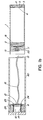
- Figure 1a illustrates a friction wire activated pyrophoric flare according to a first embodiment of the invention.
- the main body of the pyrophoric flare consists of an outer cylindrical tubular shell 1 and a rupturing disc 2 near the flare's base that are formed together as a single piece which is made by impact extrusion.
- This provides a perfect seal between rupturing disc 2 and outer shell 1 since no mechanical attachment is required.
- This arrangement fulfils an essential requirement for a perfectly sealed reservoir containing the pyrophoric liquid 17, the outer end of the tubular shell 1 being sealed with a cover assembly 3 containing a second rupturing disc 4.
- the cover 3 and rupturing disc 4 are formed as a single piece and sealed to the inner edge of the open end of tubular shell 1 by Loctite* coated threads or, alternatively, by welding.
- a nozzle cap 5 and filling plug 7 are mounted onto the cover 3.
- a piston 18 with O-ring 22 is located adjacent rupturing disc 2 inside the cylindrical shell 1.
- the cover assembly 3 contains a central outer cylindrical recess in front of rupturing disc 4 with a nozzle cap 5 being fixed in that recess. That nozzle cap 5 includes a central calibrated nozzle 6 through which the pyrophoric liquid 17 can be ejected once rupturing disc 4 fails upon activation of the flare.
- the rupturing disc 4 isolates the nozzle cap 5 from the pyrophoric liquid until the flare is activated.
- this cover assembly 3 is free of any sealing gaskets or O-rings that might leak or react with the pyrophoric liquid.
- the cover assembly 3 also includes a filling plug 7 for an opening in the cover, located between the central recess and outer edge of cover 3, through which pyrophoric liquid 17 can be added to the interior of cylindrical shell 1.
- the filling plug 7 can be easily sealed into that opening by various methods including * Trade Mark Teflon* tape on threads.
- the pyrophoric liquid may be one of the alkyl aluminum compounds that burns spontaneously when s
- the tubular shell 1 extends rearwardly of the first rupturing disc 2 with its outer edge being crimped at 8 into a notch that encircles the outer surface of cylindrical flare base 9.
- the outer surface of flare base 9 rests against an inner flange of shell 1 and against a holder 20 for the gas generator 11 and a friction wire ignition mechanism, which holder is positioned so that the gas generator 11 is adjacent the rupturing disc 2.
- the outer edge of holder 20 rests against a further inner flange of shell 1, the holder 20 being connected and sealed to shell 1.
- a preferred type of gas generator 11 is shown in more detail in Figure 4.
- the gas generator 11, in this embodiment, comprises a thin disc of energetic materials that can be ignited by a suitable ignition mechanism to produce gases and raise the pressures in the flare. That thin disc 11 is fixed in position in a central recessed portion of holder 20 so that it is located near rupturing disc 2 which will rupture once pressure generated by the gas generator 11 reaches a predetermined value.
- the friction wire ignition mechanism and holder 20 are illustrated in more detail in the enlarged view of Figure 5.
- a central bore extends through holder 20 to a cylindrical recess next to the gas generator 11, an igniter cup 50 being located in that recess with an open end of cup 50 facing gas generator 11.
- An opening in the bottom of igniter cup 50 is aligned with a central bore through holder 20.
- a friction wire 12 extends through the central bore and the opening in the bottom of cup 50 up to and through a central opening in the gas generating disc 11.
- the end of friction wire 12 extends just through the central opening 44 (see enlarged view of disc in Figure 4) of disc 11 so that it is free standing in that central opening.
- the igniter cup 50 contains an energetic composition packed around the friction wire 12.
- That friction wire 12 is a metallic wire coated with red phosphorous, at least the end of the wire extending past cup 50 towards gas generator 11.
- the friction sensitive red phosphorous on the wire will burn and ignite the energetic composition in cup 50 which then produces a flame and sufficient heat to initiate the gas generator 11. This will be explained in more detail later with respect to Figure 1b which illustrates the operation of the ignition system as the flare is ejected from the launcher tube.
- the friction wire 12 extends towards the flare's base through the central bore of holder 20 and a central opening in a squeeze cap 13 that is cup shaped.
- the open end of cap 13 is connected to a cylindrical protrusion of holder 20 which extends outward from a central cylindrical recess 52 in holder 20.
- the recess 52 in holder 20 is in the opposite surface of holder 20 from that which holds gas generator 11.
- the wire 12 exits the central opening in squeeze cap 13 and extends in a groove along the end of cap 13 to its outer cylindrical surface with wire 12 then extending back along that surface towards recess 52 in holder 20 where wire 12 is connected by joint 51 to an arming cable 16.
- the arming cable 16 is coiled inside of recess 52 and has its other end connected to an anchoring pin 21 of the safety locking sleeve 14 as illustrated in Figure 1b which shows the arming cable 16 after it is pulled out from recess 52 as the flare exits a launcher tube 80. That arming cable 16, also pulls friction wire 12 out of igniter cup 50, igniting the energetic composition packed in cup 50 as the flare is ejected from the launcher tube 80.
- the central bore through holder 20, in which the friction wire 12 is normally positioned until the flare is activated, has a conical surface as shown in Figure 5 which extends outward from the recess containing the igniter cup 50 to the end of a cylindrical protrusion 19, protrusion 19 extending outwardly from the recess 52 in holder 20.
- a conical septum 15, named Taper Septum is located in and surrounds the friction wire 12 in the conical cavity formed by that conical surface.
- a second cylindrical septum 15', named Backup Septum surrounding the friction wire 12 is squeezed against the exterior of the Taper Septum 15 by a conical protrusion extending from the inner bottom of squeeze cap 13, that protrusion compressing the two shaped septums 15, 15' into the conical cavity.
- the friction wire 12 extends through a central opening in those septums but the hole created by removal of the friction wire 12 during ignition of the flare is hermetically closed by the two squeezed septums 15 and 15'.
- These septums are designed to function together in a range of-54°C to +71°C and to hold pressures of over 8.3 MPa (1200 psi) without leaking.
- Each of those septums have very specific sealing roles.
- the Taper Septum 15 is the main septum which is made of soft silicone to provide an efficient seal under very cold temperature.
- the cylindrical Backing Septum 15' compresses the Taper Septum and is made of harder silicone which provides an efficient seal at a higher temperature range.
- the flare base 9, to which the shell 1 is crimped at 8 contains a cylindrical opening in which a safety locking sleeve 14 is located, the sleeve 14 having flanges 25 that fit into a further cylindrical recess in the holder 20 adjacent the recess containing the arming cable 16.
- the flanges 25 are held in that recess by the inner end of base 9 which has an inner annular recess 26 adjacent that inner end.
- Two further inner flanges 24 of the locking sleeve 14 are located next to that annular recess 26 (see Figure la) and are expandable, upon activation of impulse cartridge 10, so as to be shoved into recess 26 locking this safety locking sleeve 14 in position in the base (see Figure 1b).
- the expandable flanges 24 are formed by cuts in the wall of the sleeve 14 and are located on opposite sides of sleeve 14 as shown in more detail in Figure 3a and 3b.
- An anchoring pin 21 is connected to sleeve 14 between two of the flanges 25 as shown in Figure 3a and 3b with one end of arming cable 16 being connected to pin 21 as illustrated in Figure 3c.
- the main body of safety locking sleeve 14 fits into the cylindrical opening through base 9 with an impulse cartridge 10, a separate element, being located in the sleeve 14 in the cavity of base 9.
- the flare including the base 9 and impulse cartridge 10 are loaded into a tubular launcher 80 which is closed at one end, the flare's base 9 and impulse cartridge 10 resting against that closed end.
- the arming cable 16 is attached at one end to friction wire 12 which extends through the igniter cap 50 and the other end of cable 16 is attached to pin 21 of the safety locking sleeve 14.
- the impulse cartridge 10 located in the cavity of the flare base is first activated remotely. The shock wave and gas pressure generated by the impulse cartridge 10, crimps the flare safety locking sleeve in place by expanding flanges 24 into the annular recess 26 of base 9.
- Figure la shows flanges 24 before being expanded whereas Figure 1b shows the flanges 24 after being expanding into recess 26 to lock sleeve 14 in place. That shock wave and gas pressure also separate the flare from base 9 due to pressure generated on crimp 8, breaking it, and accelerating the flare out of the launcher tube.
- the arming cable 16 connected between the friction wire 12 and pin 21 of sleeve 14 unrolls.
- the arming cable 16 reaches full length and pulls friction wire 12 out of igniter cap 50 igniting the energetic composition in cap 50 which, in turn, produces sufficient flame and heat to initiate gas generator 11.
- the gas generator 11 and the rupturing disc 2 and 4 designs can be modified to set the distance from an aircraft at which the flare will start functioning and cause ignition of the pyrophoric liquid.
- the gas generator 11 is designed to produce gases at a predetermined rate and is, together with the calibrated rupturing discs 2 and 4, responsible for the flare's performance.
- Energetic materials in the shape of solid pellets and/or thin layers of polymer bounded materials are preferred for the gas generator rather than granules or powders.
- the type of energetic materials used would be selected according to their functions of burning rate and ignitability. For a given mass, fast burning rate materials in gas generator 11 will give shorter flare duration and higher radiometric intensities.
- a preferred configuration for a gas generator 11" is illustrated in Figure 4 and is formed of two thin annular concentric discs 41 and 42 of propellant.
- the outer disc 42 is a slow burning propellant coated with an inhibitor to protect its surfaces from being ignited all at once.
- the inner disc 41 is a fast burning propellant coated with a primer to ensure an efficient ignition.
- Various pressure/time profiles can be obtained by varying the composition of propellants, their total mass, the thickness and diameters of each disc.
- the safety locking sleeve 14 shown in Figures 1a and 1b acts as a safety device in the case of an accidental separation of the flare base 9 by rupture of crimp 8. This is best illustrated in Figures 3a to 3d.
- the flanges 25 at one end of sleeve 14 rest against the inner surface of a recess in holder 20 as shown in Figure la and are held in that recess by the inner face of base 9 when it is fastened to the flare by crimp 8.
- Two inner flanges 24 of sleeve (see Figure 3b), formed by cuts along the sleeve, are normally located next to a machined groove in the inner cavity of base 9 which forms the annular groove 26 shown in Figure la.
- the shock wave created will deform and push the two radial flanges 24 outward and into that machined groove 26 to lock the sleeve 14 and base 9 together as illustrated in Figure 1b or 3c. If the crimp 8 that connects the flare to the flare base 9 fails accidentally during handling, however, then the safety locking sleeve 14 is free to slide out of base 9 as shown in Figure 3d. This results in a safe separation of the flare from the flare base 9 without activation of the friction wire ignition mechanism. Once the sleeve 14 is separated from base 9, this effectively disarms the ignition mechanism formed by arming cable 16 and friction wire 12 since they will then not be near impulse cartridge 10.
- the friction wire ignition mechanism with a safety locking sleeve as described above is considered to be very reliable and safe for operation.
- an alternative bore rider safety ignition mechanism according to a further embodiment of the invention is considered to be equally safe or even safer.
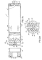
- the bore rider safety ignition according to this further embodiment of the invention is shown in Figures 2a and 2b with its operation being illustrated in Figures 2c and 2d.
- tubular outer shell 1' and rupturing disc 2' along with cover 3' and rupturing disc 4' forming the container for pyrophoric liquid 17' are identical to those in Figure la with the exception of the extension of outer shell 1 to the crimp 8.
- the tubular outer shell 1' only has a short rearward extension that is attached to the holder 38 for the gas generator 11' and the bore rider ignition mechanism.
- the gas generator 11' is again located in a recess of holder 38 adjacent the rupturing disc 2' forming a gas generator chamber next to rupture disc 2'.
- the piston 18', nozzle cap 5', nozzle 6' and filling plug 7' are identical to those in Figure la.
- the ignition mechanism for gas generator 11' located in holder 38 is designed and operates in very different manner from that shown in Figure la.
- the gas generator 11' is located in a circular recess on the inside surface of holder 38, a central opening 40 extending from the recess to a central bore 60 that extends through holder 38 along one diameter.
- a recess portion 61 extends along each side of bore 60 part way through holder 38 in a plane perpendicular to the central axis of the circular holder 38.
- Slots in the ends of the wall between the circular bore 60 and recess portions 61 extend part way down the recesses 61 as indicated by the slot edges 62 in Figure 2b, the ends of those slots forming stops for protrusions 34 extending from each side of a bore rider 30 located in cylindrical bore 60.
- the ends of the protrusions 34 extend through the slots and into the recesses 61 with springs 35 being located in recesses 61 between the closed ends of the recesses and the protrusions 34.
- the spring 35 apply pressure against the protrusions 34 in a direction to press the protrusions away from the ends of the slots in the cylinder wall towards stops 37 located near the open end of the slots.
- a rounded end of an outer extension of bore rider 30 extends towards the outer end of those slots and is held in a position by a crimp 31 of a flange on flare base 9' to keep the protrusions 34 at the bottom of the slots against the pressure exerted by springs 35.
- the flange on the flare base 9' is crimped into both ends of central bore 60 to attach the base 9' to holder 38 and to the outer shell 1' as illustrated in Figure 2a.
- the lower portion of cylindrical bore rider 30 contains 3 silicone O-rings, two of which (36 and 36') are located on either side of the central opening 40 of holder 38 in the position of bore rider 30 shown in Figures 2a and 2b.
- An opening 33 extending through bore rider 30 contains an ignitable transfer pellet 54 and is located on the side of O-ring 36' away from opening 40, a further O-ring 36" being located on the other side of opening 33 away from O-ring 36'. Therefore, in the position shown in Figure 2a, opening 33 and its transfer pellet 54 are offset from but parallel to central opening 40 of holder 38.
- opening 33 The opposite end of opening 33, away from opening 40, is aligned in Figure 2a with an opening 39 that extends from central bore 60 to a cavity in the base 9', that cavity containing an impulse cartridge 10' when the flare is inserted into a launcher.
- openings 39 and 40 are not aligned and are always separated from each other by one of the O-rings on cylindrical bore rider 30 inside of cylindrical bore 60.
- the opening 39 of holder 38 faces the cavity in flare base 9' containing the impulse cartridge 10' when the flare is in a launcher and is aligned with opening 33 containing the transfer composition pellet while the flare is in the launcher.
- the O-ring 36' will ensure that the gases produced by the initiated impulse cartridge 10' and burning transfer composition pellet in opening 33 will not reach the central opening 40 that leads to the gas generator 11'.
- the gases and shock wave produced by the impulse cartridge 10' will, however, also break the flare base crimp 31 and accelerate the flare out of a launcher tube similar to the tubular launcher 80 shown in Figure 1B.
- the rounded end of bore rider 30 will move outward slightly in cylindrical bore 60 under the action of springs 35 once the flange of flare base 9' and crimp 31 are separated from the main body of the flare.
- the rounded tip of bore rider 30 will then ride against the wall of the tubular launcher until the flare is clear of the launcher.
- a further advantage of the bore rider safety ignition mechanism is that it is considered to be a no stored energy concept, i.e. the flare by itself cannot function without an external stimuli.
- the impulse cartridge is required for this flare to function and that impulse cartridge is only present when the flare is loaded into a launcher.
Landscapes
- Engineering & Computer Science (AREA)
- Radar, Positioning & Navigation (AREA)
- Remote Sensing (AREA)
- General Engineering & Computer Science (AREA)
- Non-Portable Lighting Devices Or Systems Thereof (AREA)
- Casings For Electric Apparatus (AREA)
- Optical Communication System (AREA)
- Air Bags (AREA)
- Feeding, Discharge, Calcimining, Fusing, And Gas-Generation Devices (AREA)
- Led Device Packages (AREA)
- Led Devices (AREA)
- Aiming, Guidance, Guns With A Light Source, Armor, Camouflage, And Targets (AREA)
Applications Claiming Priority (2)
| Application Number | Priority Date | Filing Date | Title |
|---|---|---|---|
| US626453 | 1996-04-02 | ||
| US08/626,453 US5631441A (en) | 1996-04-02 | 1996-04-02 | XDM pyrophoric countermeasure flare |
Publications (3)
| Publication Number | Publication Date |
|---|---|
| EP0800051A2 true EP0800051A2 (de) | 1997-10-08 |
| EP0800051A3 EP0800051A3 (de) | 2000-01-12 |
| EP0800051B1 EP0800051B1 (de) | 2002-11-27 |
Family
ID=24510442
Family Applications (1)
| Application Number | Title | Priority Date | Filing Date |
|---|---|---|---|
| EP97301580A Expired - Lifetime EP0800051B1 (de) | 1996-04-02 | 1997-03-10 | Pyrophorischer Gegenmassnahmenleuchtsatz |
Country Status (6)
| Country | Link |
|---|---|
| US (1) | US5631441A (de) |
| EP (1) | EP0800051B1 (de) |
| AT (1) | ATE228642T1 (de) |
| AU (1) | AU711158B2 (de) |
| DE (1) | DE69717338T2 (de) |
| NO (1) | NO317323B1 (de) |
Cited By (1)
| Publication number | Priority date | Publication date | Assignee | Title |
|---|---|---|---|---|
| FR2867556A1 (fr) * | 2004-03-12 | 2005-09-16 | Lacroix Soc E | Dispositif emetteur de rayonnement infrarouge |
Families Citing this family (31)
| Publication number | Priority date | Publication date | Assignee | Title |
|---|---|---|---|---|
| US5866840A (en) * | 1997-09-17 | 1999-02-02 | Her Majesty The Queen In Right Of Canada, As Represented By The Minister Of National | Nozzles for pyrophoric IR decoy flares |
| US6092467A (en) * | 1998-01-27 | 2000-07-25 | Skyblazer, Inc. | Flare apparatus |
| DE19841113A1 (de) | 1998-09-09 | 2014-04-24 | Ernst-Christian Koch | Selbstschutzeinrichtung für Strahlflugzeuge |
| US6263797B1 (en) | 1998-12-30 | 2001-07-24 | Skyblazer, Inc. | Enhanced flare apparatus |
| US6415538B1 (en) | 2000-01-17 | 2002-07-09 | William F. Brice | Breech locking safety bracket for flare launchers |
| AU2001228616B2 (en) * | 2000-12-13 | 2005-04-28 | The Secretary Of State For Defence | Infra-red emitting decoy flare |
| US6470805B1 (en) * | 2001-04-30 | 2002-10-29 | The United States Of America As Represented By The Secretary Of The Navy | Fire retardant bio-friendly practice munition |
| US7363861B2 (en) * | 2004-08-13 | 2008-04-29 | Armtec Defense Products Co. | Pyrotechnic systems and associated methods |
| US7617776B1 (en) * | 2004-09-27 | 2009-11-17 | Diffraction, Ltd. | Selective emitting flare nanosensors |
| ES2265260B1 (es) * | 2005-01-26 | 2008-01-01 | Luis Maria Bordallo Alvarez | Procedimiento para la extincion de incendios forestales desde el aire. |
| US7992496B2 (en) * | 2005-04-28 | 2011-08-09 | Alloy Surfaces Company, Inc. | Decoys for infra-red radiation seeking missiles and methods of producing and using the same |
| US7421950B2 (en) * | 2005-04-28 | 2008-09-09 | Alloy Surfaces Company, Inc. | Decoys for infra-red radiation seeking missiles and methods of producing and using the same |
| FR2886003B1 (fr) * | 2005-05-20 | 2007-08-17 | Lacroix Soc E | Cartouche d'entrainement a securite simplifiee |
| FR2886004B1 (fr) * | 2005-05-20 | 2007-08-17 | Lacroix Soc E | Dispositif emetteur de rayonnement notamment pour la protection d'aeronef |
| US8146502B2 (en) | 2006-01-06 | 2012-04-03 | Armtec Defense Products Co. | Combustible cartridge cased ammunition assembly |
| US20100274544A1 (en) * | 2006-03-08 | 2010-10-28 | Armtec Defense Products Co. | Squib simulator |
| US7913625B2 (en) * | 2006-04-07 | 2011-03-29 | Armtec Defense Products Co. | Ammunition assembly with alternate load path |
| FR2906359A1 (fr) * | 2006-09-27 | 2008-03-28 | Lacroix Soc E | Projectile stabilise mis en oeuvre sur trajectoire, notamment leurre. |
| WO2010082881A1 (en) | 2009-01-16 | 2010-07-22 | Saab Ab | An arrangement at an aircraft of a dispenser unit for countermeasures |
| WO2010082882A1 (en) | 2009-01-16 | 2010-07-22 | Saab Ab | Dispenser unit for countermeasures |
| EP2616757B1 (de) | 2010-09-17 | 2018-08-22 | Amtec Corporation | Pyrophor-projektil |
| US8807040B2 (en) | 2011-07-07 | 2014-08-19 | James Y. Menefee, III | Cartridge for multiplex load |
| EP2739930B1 (de) | 2011-08-04 | 2016-10-12 | Polywad, Inc. | Rückstossabgeschwächtes nutzlastträgersystem |
| US10054410B2 (en) | 2011-08-04 | 2018-08-21 | James Y. Menefee, III | Cartridge for handheld payload launcher system |
| WO2013020025A2 (en) * | 2011-08-04 | 2013-02-07 | Polywad, Inc. | Handheld payload launcher system |
| US8967046B2 (en) | 2012-11-30 | 2015-03-03 | Alliant Techsystems Inc. | Gas generators, launch tubes including gas generators and related systems and methods |
| US10281248B2 (en) * | 2015-11-11 | 2019-05-07 | Northrop Grumman Innovation Systems, Inc. | Gas generators, launch tube assemblies including gas generators, and related systems and methods |
| US9574857B1 (en) * | 2015-12-28 | 2017-02-21 | Combined Systems, Inc. | Trip flare with flash bang |
| US11053007B1 (en) * | 2019-12-30 | 2021-07-06 | The United States Of America As Represented By The Secretary Of The Army | Device for dispensing pyrophoric particulate materials |
| GB2601782B (en) * | 2020-12-10 | 2024-09-11 | Bae Systems Plc | Countermeasure device |
| GB2641925A (en) * | 2024-06-18 | 2025-12-24 | Leonardo UK Ltd | A round comprising an active decoy |
Family Cites Families (8)
| Publication number | Priority date | Publication date | Assignee | Title |
|---|---|---|---|---|
| US2963975A (en) * | 1958-05-05 | 1960-12-13 | Musser C Walton | Cloud seeding carbon dioxide bullet |
| US3970003A (en) * | 1974-10-16 | 1976-07-20 | Avco Corporation | Pyrophoric flare |
| DE4131096C2 (de) * | 1991-09-18 | 1994-12-15 | Buck Chem Tech Werke | Verfahren und Vorrichtung zum Schutz eines Schiffes vor Flugkörpern mit Zweifarben-IR-Zielsuchköpfen |
| US5313888A (en) * | 1992-05-05 | 1994-05-24 | Martin Brian D | Pull-wire igniter for flares |
| FR2694804B1 (fr) * | 1992-08-11 | 1994-09-16 | Poudres & Explosifs Ste Nale | Leurre stabilisée et propulsé, émettant dans l'infrarouge. |
| US5400712A (en) * | 1993-04-30 | 1995-03-28 | Alliant Techsystems Inc. | Decoy flare |
| FR2706202B1 (fr) * | 1993-06-08 | 1995-09-01 | Lacroix E Tous Artifices | Dispositif d'éjection simultanée de deux fluides, notamment pyrotechniques. |
| USH1603H (en) * | 1995-11-07 | 1996-11-05 | The United States Of America As Represented By The Secretary Of The Navy | Flare with safe-and-arm ignition system |
-
1996
- 1996-04-02 US US08/626,453 patent/US5631441A/en not_active Expired - Fee Related
-
1997
- 1997-03-06 AU AU15141/97A patent/AU711158B2/en not_active Ceased
- 1997-03-10 AT AT97301580T patent/ATE228642T1/de not_active IP Right Cessation
- 1997-03-10 DE DE69717338T patent/DE69717338T2/de not_active Expired - Fee Related
- 1997-03-10 EP EP97301580A patent/EP0800051B1/de not_active Expired - Lifetime
- 1997-04-01 NO NO19971472A patent/NO317323B1/no unknown
Cited By (1)
| Publication number | Priority date | Publication date | Assignee | Title |
|---|---|---|---|---|
| FR2867556A1 (fr) * | 2004-03-12 | 2005-09-16 | Lacroix Soc E | Dispositif emetteur de rayonnement infrarouge |
Also Published As
| Publication number | Publication date |
|---|---|
| DE69717338T2 (de) | 2003-09-18 |
| EP0800051A3 (de) | 2000-01-12 |
| US5631441A (en) | 1997-05-20 |
| EP0800051B1 (de) | 2002-11-27 |
| NO971472D0 (no) | 1997-04-01 |
| NO971472L (no) | 1997-10-03 |
| ATE228642T1 (de) | 2002-12-15 |
| NO317323B1 (no) | 2004-10-11 |
| AU1514197A (en) | 1997-10-09 |
| DE69717338D1 (de) | 2003-01-09 |
| AU711158B2 (en) | 1999-10-07 |
Similar Documents
| Publication | Publication Date | Title |
|---|---|---|
| EP0800051B1 (de) | Pyrophorischer Gegenmassnahmenleuchtsatz | |
| EP1342981B9 (de) | Von einem Rohr verschossene Rakete | |
| US4493240A (en) | Parachute line cutting device | |
| US5561259A (en) | Decoy flare with sequencer ignition | |
| US6619029B2 (en) | Rocket motors with insensitive munitions systems | |
| US3672301A (en) | Cartridge | |
| US6363855B1 (en) | Solid propellant rocket motor thermally initiated venting device | |
| US6349650B1 (en) | Launchable flameless expulsion grenade | |
| US3967552A (en) | Percussion ignition system for a smokeless, flashless, low noise cartridge | |
| US3712224A (en) | Decoy flare with traveling ignition charge | |
| US4392432A (en) | Air burst munitions simulator | |
| US4643071A (en) | Recoilless launching device | |
| USH1603H (en) | Flare with safe-and-arm ignition system | |
| JPH06246650A (ja) | 撃発装置用のプラスチック製の薬筒 | |
| US2457839A (en) | Rocket | |
| US4227460A (en) | Practice war head device | |
| US3820462A (en) | Aerial signal unit | |
| US4099465A (en) | Ignition device for missile motors | |
| US5335600A (en) | Propellant charge igniter | |
| EP3341676B1 (de) | Patronenmunition | |
| US3855930A (en) | Personnel distress signal | |
| US5337672A (en) | Locking device for a casing containing pyrotechnic materials | |
| US2828692A (en) | Electrical igniter | |
| US6578488B2 (en) | Safety device for a pyrotechnic impact fuse of a ballistic high explosive shell | |
| US9995563B2 (en) | Cartridge with safety fuse in the drive system, and method for producing it |
Legal Events
| Date | Code | Title | Description |
|---|---|---|---|
| PUAI | Public reference made under article 153(3) epc to a published international application that has entered the european phase |
Free format text: ORIGINAL CODE: 0009012 |
|
| AK | Designated contracting states |
Kind code of ref document: A2 Designated state(s): AT BE DE FR GB |
|
| PUAL | Search report despatched |
Free format text: ORIGINAL CODE: 0009013 |
|
| AK | Designated contracting states |
Kind code of ref document: A3 Designated state(s): AT BE DE FR GB |
|
| RIC1 | Information provided on ipc code assigned before grant |
Free format text: 7F 42B 4/26 A, 7F 42B 5/15 B |
|
| 17P | Request for examination filed |
Effective date: 20000204 |
|
| GRAG | Despatch of communication of intention to grant |
Free format text: ORIGINAL CODE: EPIDOS AGRA |
|
| 17Q | First examination report despatched |
Effective date: 20020430 |
|
| GRAG | Despatch of communication of intention to grant |
Free format text: ORIGINAL CODE: EPIDOS AGRA |
|
| GRAH | Despatch of communication of intention to grant a patent |
Free format text: ORIGINAL CODE: EPIDOS IGRA |
|
| GRAH | Despatch of communication of intention to grant a patent |
Free format text: ORIGINAL CODE: EPIDOS IGRA |
|
| GRAA | (expected) grant |
Free format text: ORIGINAL CODE: 0009210 |
|
| AK | Designated contracting states |
Kind code of ref document: B1 Designated state(s): AT BE DE FR GB |
|
| REF | Corresponds to: |
Ref document number: 228642 Country of ref document: AT Date of ref document: 20021215 Kind code of ref document: T |
|
| REG | Reference to a national code |
Ref country code: GB Ref legal event code: FG4D |
|
| REF | Corresponds to: |
Ref document number: 69717338 Country of ref document: DE Date of ref document: 20030109 |
|
| ET | Fr: translation filed | ||
| PLBE | No opposition filed within time limit |
Free format text: ORIGINAL CODE: 0009261 |
|
| STAA | Information on the status of an ep patent application or granted ep patent |
Free format text: STATUS: NO OPPOSITION FILED WITHIN TIME LIMIT |
|
| 26N | No opposition filed |
Effective date: 20030828 |
|
| PGFP | Annual fee paid to national office [announced via postgrant information from national office to epo] |
Ref country code: BE Payment date: 20070222 Year of fee payment: 11 |
|
| PGFP | Annual fee paid to national office [announced via postgrant information from national office to epo] |
Ref country code: AT Payment date: 20070305 Year of fee payment: 11 |
|
| PGFP | Annual fee paid to national office [announced via postgrant information from national office to epo] |
Ref country code: DE Payment date: 20070321 Year of fee payment: 11 |
|
| PGFP | Annual fee paid to national office [announced via postgrant information from national office to epo] |
Ref country code: GB Payment date: 20070326 Year of fee payment: 11 |
|
| PGFP | Annual fee paid to national office [announced via postgrant information from national office to epo] |
Ref country code: FR Payment date: 20070319 Year of fee payment: 11 |
|
| BERE | Be: lapsed |
Owner name: THE *MINISTER OF NATIONAL DEFENCE OF HER MAJESTY'S Effective date: 20080331 |
|
| GBPC | Gb: european patent ceased through non-payment of renewal fee |
Effective date: 20080310 |
|
| PG25 | Lapsed in a contracting state [announced via postgrant information from national office to epo] |
Ref country code: AT Free format text: LAPSE BECAUSE OF NON-PAYMENT OF DUE FEES Effective date: 20080310 |
|
| REG | Reference to a national code |
Ref country code: FR Ref legal event code: ST Effective date: 20081125 |
|
| PG25 | Lapsed in a contracting state [announced via postgrant information from national office to epo] |
Ref country code: DE Free format text: LAPSE BECAUSE OF NON-PAYMENT OF DUE FEES Effective date: 20081001 |
|
| PG25 | Lapsed in a contracting state [announced via postgrant information from national office to epo] |
Ref country code: BE Free format text: LAPSE BECAUSE OF NON-PAYMENT OF DUE FEES Effective date: 20080331 |
|
| PG25 | Lapsed in a contracting state [announced via postgrant information from national office to epo] |
Ref country code: FR Free format text: LAPSE BECAUSE OF NON-PAYMENT OF DUE FEES Effective date: 20080331 |
|
| PG25 | Lapsed in a contracting state [announced via postgrant information from national office to epo] |
Ref country code: GB Free format text: LAPSE BECAUSE OF NON-PAYMENT OF DUE FEES Effective date: 20080310 |