EP0800064A2 - Capteur de pesage de forme allongé - Google Patents
Capteur de pesage de forme allongé Download PDFInfo
- Publication number
- EP0800064A2 EP0800064A2 EP97103676A EP97103676A EP0800064A2 EP 0800064 A2 EP0800064 A2 EP 0800064A2 EP 97103676 A EP97103676 A EP 97103676A EP 97103676 A EP97103676 A EP 97103676A EP 0800064 A2 EP0800064 A2 EP 0800064A2
- Authority
- EP
- European Patent Office
- Prior art keywords
- load cell
- strain
- measuring body
- measuring
- force
- Prior art date
- Legal status (The legal status is an assumption and is not a legal conclusion. Google has not performed a legal analysis and makes no representation as to the accuracy of the status listed.)
- Granted
Links
Images

Classifications
-
- G—PHYSICS
- G01—MEASURING; TESTING
- G01G—WEIGHING
- G01G3/00—Weighing apparatus characterised by the use of elastically-deformable members, e.g. spring balances
- G01G3/12—Weighing apparatus characterised by the use of elastically-deformable members, e.g. spring balances wherein the weighing element is in the form of a solid body stressed by pressure or tension during weighing
- G01G3/14—Weighing apparatus characterised by the use of elastically-deformable members, e.g. spring balances wherein the weighing element is in the form of a solid body stressed by pressure or tension during weighing measuring variations of electrical resistance
- G01G3/1402—Special supports with preselected places to mount the resistance strain gauges; Mounting of supports
- G01G3/1408—Special supports with preselected places to mount the resistance strain gauges; Mounting of supports the supports being of the column type, e.g. cylindric
-
- G—PHYSICS
- G01—MEASURING; TESTING
- G01L—MEASURING FORCE, STRESS, TORQUE, WORK, MECHANICAL POWER, MECHANICAL EFFICIENCY, OR FLUID PRESSURE
- G01L1/00—Measuring force or stress, in general
- G01L1/20—Measuring force or stress, in general by measuring variations in ohmic resistance of solid materials or of electrically-conductive fluids; by making use of electrokinetic cells, i.e. liquid-containing cells wherein an electrical potential is produced or varied upon the application of stress
- G01L1/22—Measuring force or stress, in general by measuring variations in ohmic resistance of solid materials or of electrically-conductive fluids; by making use of electrokinetic cells, i.e. liquid-containing cells wherein an electrical potential is produced or varied upon the application of stress using resistance strain gauges
- G01L1/2206—Special supports with preselected places to mount the resistance strain gauges; Mounting of supports
- G01L1/2218—Special supports with preselected places to mount the resistance strain gauges; Mounting of supports the supports being of the column type, e.g. cylindric, adapted for measuring a force along a single direction
Definitions
- the invention relates to a load cell or a force transducer with a rod-shaped measuring body, which preferably has spherical force introduction surfaces at its front ends, and with strain transducers mounted on the measuring body between the force introduction surfaces and connected as a Wheatstone bridge.
- the strain transducers are arranged symmetrically to the center plane between the center points of the spherical force introduction surfaces.
- the strain transducers can either be designed in the form of a band symmetrical with respect to its longitudinal axis, which is placed around a cylindrical circumferential surface in the middle plane mentioned, or it can be symmetrical to the four surfaces with a measuring rod of square cross section Middle plane each be arranged as a half-bridge or as a full-bridge arrangements of strain gauges.
- the strain transducers are positioned both symmetrically to the longitudinal axis and symmetrically to the central plane between the centers of the force introduction surfaces in order to avoid measurement errors due to decentralized force application.
- Both the manufacture of the suitable strain transducers and the precise application of the strain transducers on the measuring rod are therefore complex and expensive in the known load cell.
- the invention has for its object to reduce the construction costs and thus the manufacturing costs of a load cell of the type mentioned, without this being associated with a loss of measurement accuracy.
- this object is achieved in that two strain transducers, each forming a half-bridge, are arranged only on two opposite sides of the measuring body in such a way that the longitudinal central axis of the measuring body and the central axis of at least one strain transducer of the half-bridge lie in a common plane, that at least one strain transducer Half bridges are arranged off-center with respect to the central plane between the force introduction surfaces and / or the longitudinal central axis.
- the load cell according to the invention dispenses with an arrangement of strain transducers completely surrounding the measuring body or at least at an angular distance of 90 °, as well as a symmetrical arrangement of the strain transducers with respect to a center of symmetrical stresses.
- This is the case, for example, with an expansion transducer that is reduced to two application points and is at least partially off-center mechanically adjusted by suitable material removal or electrically the measuring body in the sense of a symmetrization of its measuring behavior, and thereby overall a balanced measuring behavior also achieved with respect to force inputs inclined to the longitudinal axis and a high measuring accuracy.
- the load cell according to the invention is characterized by a number of advantages.
- the application effort is low in terms of material and time, since strain sensors are only to be applied to two opposite surfaces of the measuring body. This can be done in one operation.
- the adjustment of the measuring body can be carried out easily, for example according to the rotation adjustment method described in patent application P 44 16 442.4.
- the strain transducers of a half-bridge are arranged on a common carrier. This reduces the wiring effort, since the half bridges on the carrier are already connected internally.
- the manufacturing costs of the half-bridge extensometers are low in a one-piece design. Furthermore, this achieves a high degree of accuracy in the position of the strain transducers relative to one another in the longitudinal and transverse directions and additionally simplifies the application of the strain transducers.
- the common carrier also improves the behavior in relation to temperature sensitivity, since the longitudinal and transverse transducers inevitably consist of adjacent film sections and therefore have the same temperature coefficient.
- the application and wiring complexity can further be kept small in that each half-bridge is connected to only one compensation element for linearization or temperature compensation or that in total only one compensation element is used for linearization or temperature compensation.
- the additional circuitry and connection surfaces for the strain transducers, the compensation elements and connecting cables to devices for processing and evaluating the measurement signals can be provided on a central support attached to the measuring body between the strain transducers, for example in the form of a foil circuit board .
- the elements required for electrical adjustment according to patent application P 44 16 442.4 can be provided on the carrier. This simplifies production and avoids asymmetries.
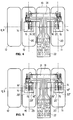
- the load cell shown in FIG. 1 consists of a measuring body 1 designed as a pressure rod, which has a slim central measuring section 2 with a square cross section and stepped, cylindrical end sections 3, 4.
- the measuring section 2 can also have a circular or polygonal cross section.
- the end faces of the End sections 3, 4 have spherical force introduction surfaces 5, 6, the center points of which lie on the central longitudinal axis 7 and which have the same radius.
- One or both of the end sections 3, 4 can instead also have flat force introduction surfaces and / or devices for connection to force introduction components, for example threads or transverse bores, can be provided on the end sections.
- the measuring body 1 is symmetrical in several respects.
- Axes of symmetry are the longitudinal axis 7 and two axes 8, 9 crossing the longitudinal axis 7 in the middle between the force introduction surfaces 5, 6 and perpendicular to the surfaces of the measuring section 2.
- the front surface of the measuring section 2 visible in FIG opposite rear surface with 11 and the two surfaces perpendicular to the surfaces 10, 11 are designated 12, 13.
- a carrier 14 with strain transducers 15, 16, an E-module compensation element 17, a linearization element 18 and the ends of a conductor foil 19 are each arranged in a symmetrical arrangement.
- the carrier 14 with the strain transducers 15, 16 is usually a foil strain gauge with two measuring grids arranged on a carrier foil.
- the strain transducers 15, 16 are each centered on a support 14 relative to a central axis 20, and the supports 14 are applied to the surfaces 10, 11 such that the central axes 20 lie in a common plane going through the longitudinal axis 7.
- the supports 14 are positioned on the surfaces 10, 11 such that the strain transducers 15 designed for measuring the longitudinal expansion are centered with respect to the central plane defined by the axes 8, 9.
- the strain transducers 16, which detect the transverse expansion of the measuring body 1, are accordingly arranged outside the central plane defined by the axes 8, 9.
- An embodiment is not shown in which the center of the extensometer measuring the longitudinal expansion is also outside the central plane defined by the axes 8, 9.
- the strain transducers 15, 16 are applied to the surfaces 10, 11 in such a way that both the strain transducers 15 provided for measuring the longitudinal expansion and the transverse expansion transducers 16 are applied with respect to the central plane defined by the axes 8, 9 are centered.
- the central axes 20 of the longitudinal extensometers 15 and the longitudinal axis 7 lie in a common plane.
- the central axes 20 'of the transverse expansion sensors 16 are eccentric to this common plane.
- each strain sensor 16 has two sensor elements 16 ', 16''for detecting the transverse expansion.
- Both the strain transducers 15 provided for the measurement of the longitudinal expansion and the transducer elements 16 ′, 16 ′′ of the transverse expansion transducer are centered with respect to the central plane defined by the axes 8, 9.
- the central axes 20 ', 20''of the transducer elements 16', 16 '' are eccentric to the central axes 20 and have the same distance from the central axes 20, and they (not shown) also eccentrically to the central plane defined by the axes 8, 9 can be arranged both below and above the same.
- the longitudinal strain sensors 15 are arranged between the sensor elements 16 ', 16''of the strain sensor 16 for the transverse expansion.
- Also not shown is an embodiment in which the two transducer elements of the transverse expansion transducer are arranged centrally with respect to the central axes 20, but eccentrically with respect to the central plane defined by the axes 8, 9, preferably at the same distance from the latter
- the strain transducers 15, 16, the modulus of elasticity compensation elements 17 and the linearization elements 18 are connected in a conventional manner to connection surfaces in a head region 21 of the conductor foils 19 by means of flexible connecting tapes.
- the head region 21 extends from the surface 10 over the surface 13 to the surface 11 and is fastened on the surfaces 10, 13, 11.
- Further compensation elements are arranged in a region 22 of the conductor foil 19, which is designed to be flexible.
- the connection of the strain transducers 15, 16, the E-module compensation elements 17 and the linearization elements 18 to form a measuring bridge is shown in FIG. 3.
- both half bridges 23, 24 are each connected to an E-module compensation element 17 and a linearization element 18.
- the required linearization and compensation can also be achieved with only one linearization element 18 and one E-module compensation element 17.
- a mechanical adjustment of the measuring body 1 is carried out, for example.
- the measuring body 1 is clamped at one end section 3 or 4 and at its other end section 4 or 3 radially to the longitudinal axis 7 in the two diagonal planes of the measuring section 2 in each case and then in the opposite direction and the output signal of the measuring bridge for each load detected. If the amount of all output signals is within a tolerance limit, it is not necessary to adjust the measuring body. If individual output signals exceed the tolerance range, an adjustment is carried out by removing material from the longitudinal edges of the measuring section 2 of the measuring body 1, the amount of the material to be removed depending on the size of the respective output signal. Instead of a mechanical adjustment, the adjustment can also be carried out electrically using adjustment resistors.
Landscapes
- Physics & Mathematics (AREA)
- General Physics & Mathematics (AREA)
- Measurement Of Force In General (AREA)
- Force Measurement Appropriate To Specific Purposes (AREA)
- Media Introduction/Drainage Providing Device (AREA)
Applications Claiming Priority (2)
| Application Number | Priority Date | Filing Date | Title |
|---|---|---|---|
| DE19613038 | 1996-04-01 | ||
| DE19613038A DE19613038A1 (de) | 1996-04-01 | 1996-04-01 | Stabförmige Wägezelle |
Publications (3)
| Publication Number | Publication Date |
|---|---|
| EP0800064A2 true EP0800064A2 (fr) | 1997-10-08 |
| EP0800064A3 EP0800064A3 (fr) | 1998-08-19 |
| EP0800064B1 EP0800064B1 (fr) | 2003-06-11 |
Family
ID=7790179
Family Applications (1)
| Application Number | Title | Priority Date | Filing Date |
|---|---|---|---|
| EP97103676A Expired - Lifetime EP0800064B1 (fr) | 1996-04-01 | 1997-03-06 | Capteur de pesage de forme allongée |
Country Status (3)
| Country | Link |
|---|---|
| EP (1) | EP0800064B1 (fr) |
| DE (2) | DE19613038A1 (fr) |
| ES (1) | ES2195044T3 (fr) |
Cited By (4)
| Publication number | Priority date | Publication date | Assignee | Title |
|---|---|---|---|---|
| EP1124118A1 (fr) * | 2000-02-10 | 2001-08-16 | Bizerba GmbH & Co. KG | Dispositif de pesage |
| CN103196526A (zh) * | 2013-03-13 | 2013-07-10 | 浙江省计量科学研究院 | 具有偏载隔离功能的测力称重传感器及其隔离测量方法 |
| CN105593656A (zh) * | 2013-07-26 | 2016-05-18 | 霍廷格-鲍德温测量技术设备公司 | 具有改善的变形行为的杆状力传感器 |
| JP2016525685A (ja) * | 2013-07-26 | 2016-08-25 | ホッティンゲル・バルドヴィン・メステクニーク・ゲゼルシヤフト・ミト・ベシュレンクテル・ハフツング | 調整を簡素化した棒状の力変換器 |
Families Citing this family (2)
| Publication number | Priority date | Publication date | Assignee | Title |
|---|---|---|---|---|
| DE19841025A1 (de) * | 1998-09-08 | 2000-03-09 | Hbm Waegetechnik Gmbh | Plattformwaage |
| DE102017117553A1 (de) * | 2017-08-02 | 2019-02-07 | Neumann & Müller Gmbh & Co. Kg | Lastmesseinrichtung und Betriebsverfahren hierfür |
Family Cites Families (6)
| Publication number | Priority date | Publication date | Assignee | Title |
|---|---|---|---|---|
| DE2625888A1 (de) * | 1976-06-09 | 1977-12-22 | Siemens Ag | Kraftmesszelle mit einem stauchkoerper |
| DE8030920U1 (de) * | 1980-11-19 | 1982-10-14 | Philips Patentverwaltung Gmbh, 2000 Hamburg | Kraftaufnehmer |
| DE3236532A1 (de) * | 1982-10-02 | 1984-04-05 | Philips Patentverwaltung Gmbh, 2000 Hamburg | Kraftaufnehmer |
| DE3427573A1 (de) * | 1984-07-26 | 1986-02-06 | Philips Patentverwaltung Gmbh, 2000 Hamburg | Kraftaufnehmer |
| JPH0194234A (ja) * | 1987-10-06 | 1989-04-12 | Kyowa Electron Instr Co Ltd | 荷重変換器 |
| US4815547A (en) * | 1987-11-30 | 1989-03-28 | Toledo Scale Corporation | Load cell |
-
1996
- 1996-04-01 DE DE19613038A patent/DE19613038A1/de not_active Ceased
-
1997
- 1997-03-06 DE DE59710246T patent/DE59710246D1/de not_active Expired - Lifetime
- 1997-03-06 ES ES97103676T patent/ES2195044T3/es not_active Expired - Lifetime
- 1997-03-06 EP EP97103676A patent/EP0800064B1/fr not_active Expired - Lifetime
Cited By (7)
| Publication number | Priority date | Publication date | Assignee | Title |
|---|---|---|---|---|
| EP1124118A1 (fr) * | 2000-02-10 | 2001-08-16 | Bizerba GmbH & Co. KG | Dispositif de pesage |
| CN103196526A (zh) * | 2013-03-13 | 2013-07-10 | 浙江省计量科学研究院 | 具有偏载隔离功能的测力称重传感器及其隔离测量方法 |
| CN105593656A (zh) * | 2013-07-26 | 2016-05-18 | 霍廷格-鲍德温测量技术设备公司 | 具有改善的变形行为的杆状力传感器 |
| JP2016525685A (ja) * | 2013-07-26 | 2016-08-25 | ホッティンゲル・バルドヴィン・メステクニーク・ゲゼルシヤフト・ミト・ベシュレンクテル・ハフツング | 調整を簡素化した棒状の力変換器 |
| US9791332B2 (en) | 2013-07-26 | 2017-10-17 | Hottinger Baldwin Messtechnik Gmbh | Rod-shaped force transducer with improved deformation behavior |
| RU2660394C2 (ru) * | 2013-07-26 | 2018-07-06 | Хоттингер Бальдвин Месстехник Гмбх | Стержневой датчик силы с упрощенной настройкой |
| US10067009B2 (en) | 2013-07-26 | 2018-09-04 | Hottinger Baldwin Messtechnik Gmbh | Rod-shaped force transducer with simplified adjustment |
Also Published As
| Publication number | Publication date |
|---|---|
| ES2195044T3 (es) | 2003-12-01 |
| EP0800064B1 (fr) | 2003-06-11 |
| EP0800064A3 (fr) | 1998-08-19 |
| DE59710246D1 (de) | 2003-07-17 |
| DE19613038A1 (de) | 1997-10-02 |
Similar Documents
| Publication | Publication Date | Title |
|---|---|---|
| DE3634855C1 (de) | Kapazitive Messanordnung zur Bestimmung von Kraeften und/oder Druecken | |
| DE3232817C1 (de) | Biegefeder | |
| EP3149439B1 (fr) | Capteur de couple et procédé pour détecter des couples s'exerçant sur une articulation d'un robot à bras articulé ou dans cette articulation | |
| DE2824121C2 (de) | Dehnungsmeßvorrichtung | |
| DE3213319A1 (de) | Einrichtung zum messen von kraft- und momentkomponenten in mehreren richtungen | |
| DE2900614C3 (de) | Kraftmeßwandler | |
| DE3611336A1 (de) | Kraft-drehmoment-fuehler | |
| EP0136437B1 (fr) | Corps de mesure de la force à plusieurs constituants et corps de mesure du moment avec des jauges de contrainte | |
| DE3218577A1 (de) | Kraftwandler | |
| DE2200211C3 (de) | Kraftmeßdose | |
| DE3342817C2 (de) | Meßnabe | |
| DE69005370T2 (de) | Membranmessfühler mit Konzentration von Deformationen. | |
| DE4012829C2 (de) | Vorrichtung zur mehrdimensionalen Kraftmessung und daraus abgeleiteten Größen durch Meßwertaufnahme mittels elektrischer Sensoren, z. B. Dehnungsmeßstreifen | |
| EP0800064B1 (fr) | Capteur de pesage de forme allongée | |
| DE2631698C2 (de) | Kraftmeßwandler | |
| DE2729150C2 (de) | Kraftaufnehmer | |
| EP0410097A2 (fr) | Capteur de force | |
| EP0338325A1 (fr) | Dispositif de mesure de force du type d'anneau à torsion | |
| DE102004033925B4 (de) | Drehmoment-Messaufnehmer | |
| DE3241850A1 (de) | Kraftmessvorrichtung | |
| DE2917966C2 (de) | Einrichtung zur Messung von Kraftkomponenten in Gelenken | |
| DE2802176B2 (de) | Kraftmeßgerät in Dehnungsmeßstreifentechnik, insbesondere für die Untersuchung von Werkstoffprüfmaschinen | |
| AT394448B (de) | Vorrichtung zum messen von in eisenbahnschienen oder aehnlichen belasteten balken wirkenden kraeften | |
| DE3701372A1 (de) | Flaechenfoermiger kraftaufnehmer | |
| EP0447782A2 (fr) | Capteur de force de flexion, notamment pour balances |
Legal Events
| Date | Code | Title | Description |
|---|---|---|---|
| PUAI | Public reference made under article 153(3) epc to a published international application that has entered the european phase |
Free format text: ORIGINAL CODE: 0009012 |
|
| AK | Designated contracting states |
Kind code of ref document: A2 Designated state(s): DE ES FR GB IT NL |
|
| PUAL | Search report despatched |
Free format text: ORIGINAL CODE: 0009013 |
|
| AK | Designated contracting states |
Kind code of ref document: A3 Designated state(s): DE ES FR GB IT NL |
|
| 17P | Request for examination filed |
Effective date: 19990125 |
|
| 17Q | First examination report despatched |
Effective date: 20020208 |
|
| GRAH | Despatch of communication of intention to grant a patent |
Free format text: ORIGINAL CODE: EPIDOS IGRA |
|
| GRAH | Despatch of communication of intention to grant a patent |
Free format text: ORIGINAL CODE: EPIDOS IGRA |
|
| GRAA | (expected) grant |
Free format text: ORIGINAL CODE: 0009210 |
|
| AK | Designated contracting states |
Designated state(s): DE ES FR GB IT NL |
|
| REG | Reference to a national code |
Ref country code: GB Ref legal event code: FG4D Free format text: NOT ENGLISH |
|
| GBT | Gb: translation of ep patent filed (gb section 77(6)(a)/1977) | ||
| REF | Corresponds to: |
Ref document number: 59710246 Country of ref document: DE Date of ref document: 20030717 Kind code of ref document: P |
|
| ET | Fr: translation filed | ||
| PLBE | No opposition filed within time limit |
Free format text: ORIGINAL CODE: 0009261 |
|
| STAA | Information on the status of an ep patent application or granted ep patent |
Free format text: STATUS: NO OPPOSITION FILED WITHIN TIME LIMIT |
|
| 26N | No opposition filed |
Effective date: 20040312 |
|
| REG | Reference to a national code |
Ref country code: DE Ref legal event code: R082 Ref document number: 59710246 Country of ref document: DE Representative=s name: SCHWEIZER, JOACHIM, DIPL.-ING., DE |
|
| REG | Reference to a national code |
Ref country code: FR Ref legal event code: PLFP Year of fee payment: 19 |
|
| PGFP | Annual fee paid to national office [announced via postgrant information from national office to epo] |
Ref country code: GB Payment date: 20150330 Year of fee payment: 19 |
|
| PGFP | Annual fee paid to national office [announced via postgrant information from national office to epo] |
Ref country code: NL Payment date: 20150330 Year of fee payment: 19 |
|
| PGFP | Annual fee paid to national office [announced via postgrant information from national office to epo] |
Ref country code: ES Payment date: 20150330 Year of fee payment: 19 Ref country code: DE Payment date: 20150429 Year of fee payment: 19 |
|
| PGFP | Annual fee paid to national office [announced via postgrant information from national office to epo] |
Ref country code: IT Payment date: 20150330 Year of fee payment: 19 Ref country code: FR Payment date: 20150330 Year of fee payment: 19 |
|
| REG | Reference to a national code |
Ref country code: DE Ref legal event code: R119 Ref document number: 59710246 Country of ref document: DE |
|
| REG | Reference to a national code |
Ref country code: NL Ref legal event code: MM Effective date: 20160401 |
|
| GBPC | Gb: european patent ceased through non-payment of renewal fee |
Effective date: 20160306 |
|
| REG | Reference to a national code |
Ref country code: FR Ref legal event code: ST Effective date: 20161130 |
|
| PG25 | Lapsed in a contracting state [announced via postgrant information from national office to epo] |
Ref country code: NL Free format text: LAPSE BECAUSE OF NON-PAYMENT OF DUE FEES Effective date: 20160401 Ref country code: DE Free format text: LAPSE BECAUSE OF NON-PAYMENT OF DUE FEES Effective date: 20161001 Ref country code: GB Free format text: LAPSE BECAUSE OF NON-PAYMENT OF DUE FEES Effective date: 20160306 Ref country code: FR Free format text: LAPSE BECAUSE OF NON-PAYMENT OF DUE FEES Effective date: 20160331 |
|
| PG25 | Lapsed in a contracting state [announced via postgrant information from national office to epo] |
Ref country code: IT Free format text: LAPSE BECAUSE OF NON-PAYMENT OF DUE FEES Effective date: 20160306 |
|
| REG | Reference to a national code |
Ref country code: ES Ref legal event code: FD2A Effective date: 20170426 |
|
| PG25 | Lapsed in a contracting state [announced via postgrant information from national office to epo] |
Ref country code: ES Free format text: LAPSE BECAUSE OF NON-PAYMENT OF DUE FEES Effective date: 20160307 |