EP0800071A2 - Tête d'essai pour une masque respiratoire - Google Patents
Tête d'essai pour une masque respiratoire Download PDFInfo
- Publication number
- EP0800071A2 EP0800071A2 EP97103070A EP97103070A EP0800071A2 EP 0800071 A2 EP0800071 A2 EP 0800071A2 EP 97103070 A EP97103070 A EP 97103070A EP 97103070 A EP97103070 A EP 97103070A EP 0800071 A2 EP0800071 A2 EP 0800071A2
- Authority
- EP
- European Patent Office
- Prior art keywords
- test head
- coating
- mask
- pressure
- test
- Prior art date
- Legal status (The legal status is an assumption and is not a legal conclusion. Google has not performed a legal analysis and makes no representation as to the accuracy of the status listed.)
- Withdrawn
Links
Images

Classifications
-
- A—HUMAN NECESSITIES
- A62—LIFE-SAVING; FIRE-FIGHTING
- A62B—DEVICES, APPARATUS OR METHODS FOR LIFE-SAVING
- A62B27/00—Methods or devices for testing respiratory or breathing apparatus for high altitudes
Definitions
- the invention relates to a test head for respiratory protection and diving masks in a shape approximating the human head with at least one air line crossing the inside of the head, the test head preferably having an opening in the region of the mouth to which the air line is connected at one end while the other end of which can be connected to air supply or removal or test devices.
- Test heads of this type are used to check the functionality of breath-controlled metering valves, for example in the case of respiratory protection and diving masks, and the masks themselves.
- inhalation and exhalation resistance, throughput and tightness are examined by strapping the mask onto the test head adapted to the shape of the human head and simulating breathing via the air line through an artificial lung with a sinusoidal pressure curve.
- the object of the present invention is to provide a test head which can be used not only for any mask sizes, but also for all the necessary functional tests, without the need to adapt the test head or even replace it.
- test head has a coating of resilient material that at least partially on it the outside of which surrounds it in a pressure-tight manner, the said opening being recessed, and in that the test head has a pressure line which connects the space between it and the coating to a compressed air supply for inflating the coating.
- the coating surrounds the test head in the sealing surface area of the mask to be put on and is fixed pressure-tight on the test head outside this area, but it can also be advantageous from certain points of view to deviate from this Design of the cover.
- a simple embodiment is that the coating completely surrounds the test head and is pressure-tightly connected to the test head at least in the neck region of the simulated head. This ensures that there are no restrictions exist with regard to the size of the mask to be checked, rather the test head would even be suitable for those masks which cover a large part of the head.
- test head itself with compressed air
- an approximately ring-shaped compressed air element made of elastically resilient material, which is arranged between the test head and the coating in the sealing surface area of the mask to be fitted and the interior of which is connected to the compressed air supply.
- This compressed air element can be designed, for example, in the form of a tube, the test head having a recess on its outside for receiving the inflatable tube. Because of its elastic nature, the coating serves here to fix the position of the tube rather than to seal the sealing surface area, which it produces only indirectly by the tube pressing it onto the edge of the mask.
- a second coating is arranged between the test head and the coating, which is pressure-tightly connected to the first coating and that the space between the first and second coating is connected to the compressed air supply.
- Such an inflatable hood has the advantage that the test head itself does not have to be pressure-tight, so it only has to extend over partial areas to ensure the stability and to fix the air line connection. This not only makes it possible to reduce the weight of the test head, but also provides access to those that cross the test head Air lines or other possible measuring lines simplified.
- test head itself must be closed pressure-tight at least in the area of the coating and can expediently consist of a solid material such as metal or plastic.
- latex for example, is recommended as the material for the coating, which can also be used as the material for the annular compressed air element, for which purpose, for example, production using the immersion method is suitable.
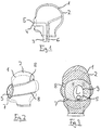
- FIG. 1 shows a test head 1 which is modeled on the human head shape and has an elastic coating 2 which almost completely surrounds it on its outside. Only in the area of the mouth and in the neck area does it have openings, the respective edge of which is fixed pressure-tight on the test head. From Figure 1 is also an air line 3 can be seen, which extends from a (not shown) air supply or exhaust or a test device in the test head while crossing the neck area of the test head and with its free end 4 in the mouth area of the test head emerges again through an opening 5.
- This air line is used, for example, to measure the throughput by connecting it to an artificial lung and supplying air from the environment via the mask to the artificial lung or transporting it in the opposite direction.
- test head has a pressure line 6 which is connected to a compressed air supply (not shown) and opens with its free end into the space between test head 1 and coating 2.
- a pressure line 6 which is connected to a compressed air supply (not shown) and opens with its free end into the space between test head 1 and coating 2.
- the coating can be inflated and pressed onto the attached mask in order to ensure a tight connection to the mask.
- the course of the pressure line 6 is irrelevant to the function of the test head, it is advisable to also introduce it through the neck area into the test head and to allow it to flow into the space between the test head and the coating at a suitable point.
- FIG. 2 shows the test head from FIG. 1 with an attached mask 7 and an inflated cover, the hidden circumference of the test head being shown in dashed lines.
- the mask 7 is only indicated schematically to simplify the illustration without its own air connection openings such as breathing valves and the like.
- two or more holding straps 8 extend, which run around the test head on the other side of the mask and ensure that the mask is pressed against the coating.
- the inflated coating presses against the sealing surfaces of the mask and is so inflated on the areas adjacent to the sealing surfaces that it is initially almost tangential to the mask runs.
- Figure 3 finally shows the test head from Figure 2 in front view and shows in particular the course of the coating 2:
- This is shown hatched in Figure 3 outside the mask area with solid lines and within the mask area with dashed lines and covers the test head 1 almost completely up to the mouth area around the opening 5 and the neck area of the test head.
- the coating has a recess 9, the main purpose of which is not to block the air line and to allow an air supply or removal through the opening 5.
- the size of the recess 9 is in itself irrelevant, but it must be ensured that it does not extend into the sealing surface area of the mask and that a pressure-tight connection between the coating 2 and the test head 1 is provided in the region of the recess 9.
- FIG. 3 it can be seen from FIG. 3 how the covering inflates outside the holding straps 8 of the mask 7 and thus indicates the same behavior for the sealing surface areas.
- FIG. 4 An alternative embodiment is shown in FIG. 4, the test head 1 again being provided with an air line 3 and a pressure line 6, which correspond to the two lines from FIG.
- a coating 12 is provided which extends only over a partial area of the test head, which must be at least somewhat larger than the sealing surface area of the mask to be put on.
- the transition region between the cover 12 and the test head 1 must be designed to be pressure-tight along the dashed lines in order to ensure that the cover is inflated when pressure is applied.
- the pressure line 6 is also so arranged that it emerges from the test head into the space between the coating and the test head in this field of view.
- FIG. 5 shows the test head from FIG. 4 with the mask 7 attached and the inflated cover 12, and clarifies that the area of the test head 1 covered by the cover 12 is completely sufficient for sealing the mask size shown.
- the mask in FIG. 5 is also only indicated schematically for the sake of simplicity and has two holding straps 8 which press the mask 7 against the test head 1 or the cover 12.
- FIG. 6 shows the test head with the mask from FIG. 5 in a front view, the representation of the coating being based on the same principle as in FIG. 3.
- the covering corresponds only to the covering 2 from FIG. 3 in the mouth area in that it has a recess 19 which is somewhat larger than the opening 5.
- the coating 12 extends - as already indicated in FIG. 4 - only over a partial area of the head, namely approximately over the field of view, and is fixed with its edge area to the test head 1 in a pressure-tight manner.
- the advantage of the present invention lies in the fact that one and the same test head can be used for the most varied mask sizes or brands and all different mask tests required for checking the mask, without having to make any adjustments to it.
- This is according to the invention achieved by the provision of a cover which is made inflatable at least in the sealing surface area.
Landscapes
- Health & Medical Sciences (AREA)
- Pulmonology (AREA)
- General Health & Medical Sciences (AREA)
- Business, Economics & Management (AREA)
- Emergency Management (AREA)
- Respiratory Apparatuses And Protective Means (AREA)
- Sampling And Sample Adjustment (AREA)
- Medicines Containing Antibodies Or Antigens For Use As Internal Diagnostic Agents (AREA)
Applications Claiming Priority (2)
| Application Number | Priority Date | Filing Date | Title |
|---|---|---|---|
| DE29605844U DE29605844U1 (de) | 1996-04-01 | 1996-04-01 | Prüfkopf für Atemschutzmasken |
| DE29605844U | 1996-04-01 |
Publications (2)
| Publication Number | Publication Date |
|---|---|
| EP0800071A2 true EP0800071A2 (fr) | 1997-10-08 |
| EP0800071A3 EP0800071A3 (fr) | 1999-02-03 |
Family
ID=8021892
Family Applications (1)
| Application Number | Title | Priority Date | Filing Date |
|---|---|---|---|
| EP97103070A Withdrawn EP0800071A3 (fr) | 1996-04-01 | 1997-02-26 | Tête d'essai pour une masque respiratoire |
Country Status (3)
| Country | Link |
|---|---|
| US (1) | US5808182A (fr) |
| EP (1) | EP0800071A3 (fr) |
| DE (1) | DE29605844U1 (fr) |
Cited By (1)
| Publication number | Priority date | Publication date | Assignee | Title |
|---|---|---|---|---|
| RU2153658C1 (ru) * | 1999-03-10 | 2000-07-27 | Ламкин Олег Борисович | Установка для исследований защитных свойств комплекса средств индивидуальной защиты |
Families Citing this family (10)
| Publication number | Priority date | Publication date | Assignee | Title |
|---|---|---|---|---|
| US6435009B1 (en) * | 1998-06-01 | 2002-08-20 | Hamilton Associates, Inc. | Portable multi-function system for testing protective devices |
| DE20000379U1 (de) | 2000-01-11 | 2000-03-23 | Stumpf, Willi, Dipl.-Ing., 69198 Schriesheim | Prüfkopf |
| US8196483B2 (en) * | 2007-12-07 | 2012-06-12 | Trudell Medical International | Systems and methods for evaluating medication delivery from valved holding chambers with a facemask using a model face |
| US7988452B2 (en) * | 2008-05-23 | 2011-08-02 | Dräger Safety AG & Co. KGaA | Test head for protective mask testing and test head system |
| US8312761B1 (en) | 2008-06-24 | 2012-11-20 | Tsi, Incorporated | Respirator test accessory |
| US8708708B1 (en) | 2009-06-29 | 2014-04-29 | Tsi, Inc. | Respirator test accessory |
| US9612176B2 (en) * | 2014-03-22 | 2017-04-04 | Hamilton Associates, Inc. | Test head assembly for use in testing protective masks |
| US10576311B2 (en) | 2017-07-18 | 2020-03-03 | Mathew Trowbridge | Remotely controlled air supply assembly |
| RU206156U1 (ru) * | 2020-10-07 | 2021-08-25 | Владимир Дмитриевич Романов | Универсальный мобильный блок подачи постоянного воздушного потока "Борей" |
| DE102022129990A1 (de) * | 2022-11-14 | 2024-05-16 | MAX-PLANCK-Gesellschaft zur Förderung der Wissenschaften e.V. | Prüfvorrichtung zur Prüfung von Mund und Nase eines Trägers bedeckenden Atemmasken |
Family Cites Families (5)
| Publication number | Priority date | Publication date | Assignee | Title |
|---|---|---|---|---|
| FR606242A (fr) * | 1925-02-19 | 1926-06-09 | Hutchinson Sa Ets | Appareil démontable pour l'essai des masques contre les gaz asphyxiants |
| FR851907A (fr) * | 1938-09-26 | 1940-01-18 | Tête d'essai pour la vérification des masques à gaz | |
| FR1429204A (fr) * | 1965-04-09 | 1966-02-18 | Tête anatomique gonflable, destinée au contrôle des masques | |
| US4796467A (en) * | 1987-04-30 | 1989-01-10 | Biosystems Inc. | Testing device for respiratory protective devices |
| DE4129848A1 (de) * | 1991-09-07 | 1993-03-11 | Draegerwerk Ag | Vorrichtung zum betreiben und pruefen von atemschutzgeraeten |
-
1996
- 1996-04-01 DE DE29605844U patent/DE29605844U1/de not_active Expired - Lifetime
-
1997
- 1997-02-26 EP EP97103070A patent/EP0800071A3/fr not_active Withdrawn
- 1997-03-26 US US08/827,083 patent/US5808182A/en not_active Expired - Fee Related
Cited By (1)
| Publication number | Priority date | Publication date | Assignee | Title |
|---|---|---|---|---|
| RU2153658C1 (ru) * | 1999-03-10 | 2000-07-27 | Ламкин Олег Борисович | Установка для исследований защитных свойств комплекса средств индивидуальной защиты |
Also Published As
| Publication number | Publication date |
|---|---|
| EP0800071A3 (fr) | 1999-02-03 |
| US5808182A (en) | 1998-09-15 |
| DE29605844U1 (de) | 1996-05-23 |
Similar Documents
| Publication | Publication Date | Title |
|---|---|---|
| DE2543778C3 (de) | Urinsammelbeutel mit einem auf seiner Innenseite vor einer Einlaßöffnung angeordneten Klappenventil | |
| EP0531729A1 (fr) | Dispositif pour opérer et tester des appareils respiratoires | |
| DE3020232A1 (de) | Muskeluebungsgeraet | |
| EP0800071A2 (fr) | Tête d'essai pour une masque respiratoire | |
| DE4111862C2 (de) | Druckmeßgerät | |
| DE3016747A1 (de) | Selbstaufblasender blasenkatheder | |
| DE102010008923A1 (de) | Richtungsventil für ein Atemschutzprodukt | |
| DE4341746C1 (de) | Beatmungsbeutel | |
| EP1116498A2 (fr) | Tête d'essai | |
| DE69401013T2 (de) | Gassammeleinheit | |
| DE1491642B1 (de) | Atemgasbeutel fuer Beatmungsgeraete | |
| DE202022001540U1 (de) | Tubekite | |
| DE1232474B (de) | Maskendichtpruefgeraet | |
| DE1498724C3 (de) | Vorrichtung zum Sammeln und Analysieren von aus den Alveolen der Lungen ausgeatmeter Luft | |
| DE2557777C3 (de) | Einrichtung zur Volumenverringerung eines betretbaren Folienbehältnisses | |
| DE3640035C2 (de) | Gerät zur Untersuchung der Lungenfunktion | |
| DE9215271U1 (de) | Behälter für Bälle | |
| DE19938667A1 (de) | Verfahren und Mittel zum Wechsel von Handschuhen | |
| DE9107222U1 (de) | Vorrichtung zur Kontrolle von Atemgeräten | |
| DE29807489U1 (de) | Beatmungsmaske | |
| DE2914858C2 (de) | Prüfgerät für Akkumulatorengehäuse | |
| DE2246473C3 (de) | Anschlußstück für ein Manometer | |
| DE2227453C3 (de) | An einen Entlüftungsnippel anschließbares Ventil | |
| DE3103981A1 (de) | Verschliessbares druckluftventil | |
| DE9305898U1 (de) | Tourniquet-Manschette |
Legal Events
| Date | Code | Title | Description |
|---|---|---|---|
| PUAI | Public reference made under article 153(3) epc to a published international application that has entered the european phase |
Free format text: ORIGINAL CODE: 0009012 |
|
| AK | Designated contracting states |
Kind code of ref document: A2 Designated state(s): AT BE CH DE FR GB IT LI NL SE |
|
| PUAL | Search report despatched |
Free format text: ORIGINAL CODE: 0009013 |
|
| AK | Designated contracting states |
Kind code of ref document: A3 Designated state(s): AT BE CH DE FR GB IT LI NL SE |
|
| STAA | Information on the status of an ep patent application or granted ep patent |
Free format text: STATUS: THE APPLICATION IS DEEMED TO BE WITHDRAWN |
|
| 18D | Application deemed to be withdrawn |
Effective date: 19990804 |