EP0800201A2 - Radiateur excimère à longue durée de vie, procédé sa fabrication et pour l'allongement de sa durée de vie ausi que dispositif pour la mise en oeuvre de ses procédés - Google Patents
Radiateur excimère à longue durée de vie, procédé sa fabrication et pour l'allongement de sa durée de vie ausi que dispositif pour la mise en oeuvre de ses procédés Download PDFInfo
- Publication number
- EP0800201A2 EP0800201A2 EP97105297A EP97105297A EP0800201A2 EP 0800201 A2 EP0800201 A2 EP 0800201A2 EP 97105297 A EP97105297 A EP 97105297A EP 97105297 A EP97105297 A EP 97105297A EP 0800201 A2 EP0800201 A2 EP 0800201A2
- Authority
- EP
- European Patent Office
- Prior art keywords
- halogen
- discharge space
- radiator
- excimer
- infrared
- Prior art date
- Legal status (The legal status is an assumption and is not a legal conclusion. Google has not performed a legal analysis and makes no representation as to the accuracy of the status listed.)
- Granted
Links
Images


Classifications
-
- H—ELECTRICITY
- H01—ELECTRIC ELEMENTS
- H01J—ELECTRIC DISCHARGE TUBES OR DISCHARGE LAMPS
- H01J61/00—Gas-discharge or vapour-discharge lamps
- H01J61/70—Lamps with low-pressure unconstricted discharge having a cold pressure < 400 Torr
-
- H—ELECTRICITY
- H01—ELECTRIC ELEMENTS
- H01J—ELECTRIC DISCHARGE TUBES OR DISCHARGE LAMPS
- H01J61/00—Gas-discharge or vapour-discharge lamps
- H01J61/02—Details
- H01J61/12—Selection of substances for gas fillings; Specified operating pressure or temperature
Definitions
- the invention relates to an excimer radiator with a discharge space which contains a halogen-containing filler gas which forms excimers under discharge conditions. Furthermore, the invention relates to a method for producing a long-life excimer radiator and a method for extending the life of such an excimer radiator as well as a device for carrying out the last-mentioned method
- Excimer emitters are used to generate high-energy UV radiation.
- Excimer radiation is also known as silent electrical discharge. This is generated in a discharge space delimited by dielectrics, in which the filling gas forming the excimers is contained.
- An excimer radiator of the type specified is known from EP-A1 0 547 366.
- various noble gases for example argon, krypton or xenon or noble gas mixtures, are proposed as filler gases, depending on the desired spectral composition of the radiation, which contain, for example, chlorine or a chlorine-containing compound, from which one or more chlorine atoms are split off in the discharge will.
- An excimer radiator designed as a planar flat radiator is known from EP-A2 0 521 553.
- the discharge space contains a halogen-containing rare gas filling, the partial pressure of the halogen being between 0.05% and 5% of the partial pressure of the rare gas.
- the well-known excimer radiator is characterized by a high irradiance.
- the maximum adjustable UV irradiance is reduced within the first 300 operating hours.
- the drop in UV irradiance is typically greater than 50% of the initial illuminance.
- the present invention is therefore based on the object of specifying an excimer radiator with a long service life and of providing a method for producing such an excimer radiator. Furthermore, the invention is based on the object of specifying a method for increasing the service life of excimer radiators and a device suitable therefor.
- the object is achieved on the basis of the excimer radiator mentioned at the outset in that the halogen content of the discharge space (16) per cm 2 of its inner surface is at least 1 ⁇ 10 -10 mol / cm 3 and at the same time as a function of the maximum power density of the radiator, expressed in the unit "watts per cm of radiator length" is set to a value in the range from 1 x 10 -7 mol / cm 3 to 1 x 10 -5 mol / cm 3 per unit of power density.
- halogen fluorine, chlorine, bromine and iodine and mixtures of these gases
- ble gas means helium, neon, argon, krypton and xenon and mixtures of these gases.
- the halogen loss can be based on a reaction of the halogen with the inner surfaces of the discharge space.
- the boundary walls of the discharge space can consist, for example, of quartz glass or of a ceramic.
- the surface reaction of the halogen can be avoided by a suitable modification of the inner surfaces delimiting the discharge space.
- such measures are complex and expensive and, moreover, the modifications produced are often not sufficiently resistant to discharge. For example, applied protective layers can peel off.
- the saturation concentration is at a halogen content of at least 1 ⁇ 10 -10 mol / cm 3 per cm 2 of the inner surface.
- This halogen content can be measured in the filling gas before surface reactions with the halogen have taken place, for example before the emitter is started up.
- the halogen content in the discharge space can be determined if all halogen bound to or in the inner surface of the discharge space is added to the halogen content of the filling gas.
- the halogen content bound to or in the inner surface of the discharge space can be determined, for example, by releasing the halogen into the discharge space by means of a suitable temperature treatment.
- This halogen content can also be determined chemically or spectroscopically. It should be noted, however, that such halogen, which delimits the discharge space inside the material Walls may also be present, is not taken into account.
- synthetic quartz glass often contains a certain amount of chlorine due to the manufacturing process.
- the specified saturation concentration of halogens in the discharge space is permanently set, a decrease in the irradiance over time is avoided in whole or in part.
- a halogen concentration above the actually sufficient saturation concentration does not have a detrimental effect on the lifetime behavior. However, it affects the radiation characteristics of the radiator and reduces its maximum power density.
- the halogen concentration to be set continues to depend on the maximum power density of the radiator. On the other hand, it is therefore necessary to observe the further dimensioning rule that the halogen content in the discharge space, depending on the maximum power density of the emitter, expressed in the unit "watt per cm emitter length", to a value in the range from 1 x 10 -7 mol / cm 3 to 1 x 10 -5 mol / cm 3 per unit of power density is set.
- the relationship between the power density and the suitable halogen content of the discharge space has been shown to be approximately linear up to a power density of approximately 200 W / cm lamp length. It can be assumed that this relationship is also valid at even higher power densities, for example at power densities around 400 W / cm.
- the length of the spotlight is only the length of the spotlight that is actually illuminated.
- the stated saturation concentration corresponds approximately to a mixture ratio of halogen: noble gas of 1:50 to 1: 500.
- mixture ratios are only given as a guide for easier orientation. It is expressly pointed out in this connection that it is not the mixing ratio, but the absolute halogen content, based on the size of the inner surface and the volume of the discharge space, and at the same time based on the maximum power density of the excimer radiator, that are decisive for the excimer radiator according to the invention. Any buffer gases in the discharge space, which can also be noble gases, are not taken into account.
- An excimer emitter in which the halogen content of the discharge space per cm 2 of its inner surface is in the range from 1 ⁇ 10 -10 mol / cm 3 to 1 ⁇ 10 -8 mol / cm 3 has proven particularly useful.
- the specified upper limit results from the increasing halogen content decreasing efficiency of the radiator.
- Halogen has a high electronegativity and usually has a lower probability of excitation compared to the noble gas. It therefore captures a relatively large number of electrons; the heater is difficult to ignite if the chlorine content is high.
- the filament density and consequently the halogen content in its atomic form increases with increasing power density of the excimer lamp.
- atomic halogen accumulates particularly easily on the boundary walls of the discharge space.
- the specified upper limit of the halogen concentration is therefore particularly relevant for excimer lamps with a high power density around 100 W per cm of lamp length, while with excimer lamps with a lower power density - without prejudice to the above-mentioned dimensioning rule with regard to the power density - this upper limit can be exceeded.
- An excimer radiator has a particularly long service life, in which the filling gas contains chlorine or a compound which releases chlorine under discharge conditions.
- a suitable chlorine-containing filling gas contains, for example, HCl with 2% Cl 2 and an inert gas, such as krypton, xenon or argon.
- An excimer emitter in which a halogen-containing reservoir is arranged in the discharge space has proven to be particularly advantageous, the concentration of the halogen in the reservoir being higher than that in the filling gas.
- the halogen in the halogen reservoir is separated from the filling gas in the discharge space. If the halogen content falls below a predetermined lower limit, the reservoir can be opened automatically or manually, the halogen contained therein being released into the discharge space.
- the halogen content of the reservoir is dimensioned such that the concentration of the halogen in the discharge space is increased by the release; for example, the target concentration of the halogen in the discharge space can be achieved by the release.
- a suitable halogen content of the reservoir thus results simply from the difference between the concentration at the lower limit and the target concentration and the volume of the discharge space.
- the reservoir has a relatively small volume compared to the volume of the discharge space.
- the halogen concentration in the reservoir is therefore relatively high.
- the reservoir can be designed, for example, in the form of a chamber made of quartz glass or a ceramic, which is broken when the said lower concentration limit is reached.
- the lower concentration limit can be determined on the basis of intensity measurements of the excimer radiation.
- the above-mentioned object is based on the method mentioned at the outset solved in that the inner surfaces of the discharge space are charged with a halogen-containing passivation gas before filling the filling gas.
- This passivation is a relatively simple modification of the inner surface of the discharge space. It can be done, for example, in a simple manner by flushing the discharge space with the halogen.
- the method according to the invention has proven to be particularly effective with regard to the extension of the service life in excimer lamps in which chlorine or a compound which releases chlorine under discharge conditions is used if chlorine is used for the passivation.
- the halogen content of the passivation gas per cm 2 of the inner surface of the discharge space is advantageously at least 1 ⁇ 10 -10 mol / cm 3 , with the proviso that it is chosen to be at least as large as the halogen content in the filling gas.
- the term "halogen content” is understood to mean the concentration of the halogen based on the volume of the discharge space.
- the passivation can take place on walls of the discharge space made of quartz glass at an elevated temperature up to 1000 ° C; with ceramic walls even at higher temperatures.
- the above-mentioned object is achieved according to the invention in that the discharge space is exposed to infrared radiation or that halogen is released from a halogen reservoir arranged in the discharge space.
- the walls delimiting the discharge space are heated by the infrared radiation. These are usually quartz glass walls. It was shown that the warming can reverse a previously depleted halogens in the filling gas.
- the halogen content of the filling gas can be regenerated.
- the loss of halogen has proven to be reversible.
- the reversibility of the halogen loss is accompanied by an extension of the life of the excimer lamp. Due to the temporary loss of halogen within the discharge space and operation with a low halogen content, there is no irreversible damage to the excimer lamp.
- the excimer radiator can be placed in an oven, for example, or it is exposed to the radiation emitted by an infrared radiator.
- halogen is released from a halogen reservoir arranged in the discharge space.
- concentration of the halogen in the reservoir is set higher than that in the filling gas.
- a halogen loss in the discharge space can be compensated for by the additional halogen from the reservoir. If the halogen content falls below a predetermined lower limit, the reservoir can be opened automatically or manually, the halogen contained therein being released into the discharge space.
- a method has proven to be particularly advantageous in which the discharge space is heated to a temperature in the range from 400 ° C. to 1000 ° C. by means of infrared rays.
- This temperature range applies to a discharge space with boundary walls made of quartz glass. If the boundary walls consist of a ceramic, such as Al 2 O 3 , temperatures above 1000 ° C are more favorable.
- Such a procedure has proven to be particularly effective in the case of chlorine-containing filling gas.
- the object stated above is achieved according to the invention in that at least one infrared radiator is provided, which is arranged adjacent to the excimer radiator, in such a way that the infrared radiation emanating from the infrared radiator heats the discharge space.
- the above-described method for extending the excimer radiator can be carried out in a simple manner at any time. To do this, only the infrared heater has to be switched on. The infrared radiation is directed towards the discharge space and heats its boundary walls. This releases the halogen absorbed or adsorbed on it.
- every oven is also suitable as an infrared heater.
- the infrared radiator is advantageously provided with a reflector, which directs the infrared radiation onto the discharge space and thereby prevents the infrared radiation from being emitted undesirably in other directions.
- the length of the infrared radiator or the total length of all infrared radiators corresponds approximately to the length of the discharge space. This effectively releases the halogen over the entire length of the discharge space.
- the infrared radiator advantageously runs or the infrared radiators run parallel to the discharge space of the excimer radiator.
- a device in which the at least one infrared radiator and the excimer radiator are electrically connected to one another in such a way that the infrared radiator is switched on after a definable time interval before or after the excimer radiator is switched on has proven particularly useful.
- This embodiment of the device has the advantage that the halogen is released in a reproducible manner from the inner surfaces delimiting the discharge space.
- Excimer emitters and infrared emitters can be switched on at the same time, so the above-mentioned time interval can also be 0.
- the operating hours are plotted on the X-axis and a relative irradiance on the Y-axis.
- Figure 1 shows the life behavior of XeCl module radiators. These generate a power density of 25 W / cm lamp length.
- the filling pressure of the filling gas in the discharge space is 750 mbar.
- Argon as a buffer gas contributes about 300 mbar to this internal pressure.
- the discharge space in these emitters is formed by the space between two quartz glass tubes which run coaxially to one another.
- the outer diameter of the discharge space is 27 mm, the inner diameter is 16 mm and the length is 343 mm.
- the curve labeled with the reference number 1 represents the service life behavior of a previously available XeCl module radiator.
- the mixing ratio of xenon to chlorine is about 1000: 1.
- the absolute chlorine content in the discharge space is below 1 x 10 -10 mol / cm 3 per cm 2 of the inner surface of the discharge space; more precisely at about 3 x 10 -11 mol / cm 3 : the inside surface of the discharge space is about 470 cm 2 .
- the concentration information relates to the volume of the discharge space.
- the curve shape designated by the reference number 2 represents the service life behavior in a XeCl module radiator in which the chlorine content of the discharge space is quintupled compared to the known excimer radiator described above.
- the mixing ratio of xenon to chlorine is therefore about 200: 1.
- the chlorine content is 1.5 x 10 -10 mol / cm 3 and cm 2 of the inner surface of the discharge space.
- the power density is approximately 30 watts per cm of illuminated spotlight length. Otherwise, the XeCl module radiators considered are identical.
- chlorine accumulates on the inner walls of the discharge space;
- the chlorine content in the filling gas therefore gradually decreases and can drop below the value of, for example, 5 ⁇ 10 -11 mol / cm 3 and cm 2 of the inner surface.
- the service life behavior of the XeCl module radiator according to the invention is characterized by only a slight and, in particular, very slow decrease in the UVB irradiance over time. After approx. 1000 hours of operation, the relative UVB irradiance only decreased by approx. 20%. However, curve 2 does not yet show whether the irradiance amounts to an end value.
- a similar result of the service life behavior results from the creep diagrams of KrCl module radiators shown in FIG . These generate a power density of 25 W / cm lamp length.
- the filling pressure of the filling gas in the discharge space is 350 mbar.
- the discharge space in these emitters is also formed by the space between two quartz glass tubes which run coaxially to one another.
- the outer diameter of the discharge space is 27 mm, the inner diameter is 16 mm and the length is 343 mm.
- reference number 3 is assigned to a creep curve, as is usually measured in a KrCl module radiator according to the prior art.
- the mixing ratio of krypton to chlorine is approximately 1000: 1.
- the absolute chlorine content in this radiator is the same as in the known XeCl module radiator described above.
- a relatively strong drop in UVC radiation intensity can be observed immediately after use of the lamp, which after approx. 300 to 400 operating hours results in a low final value, which is below 10% of the original radiation intensity.
- Curves 4 and 5 are assigned to KrCl module radiators, which differ from one another only in the mixing ratio of the filling gas. These generate a power density of 25 W / cm lamp length. A buffer gas is not included.
- the initial krypton: chlorine mixing ratio is 100: 1
- the creep curve 5 50 1.
- the latter mixing ratio corresponds to a chlorine content of approx. 6 x 10 -10 mol / cm 3 per cm 2 of the inner surface of the discharge space.
- the inside surface of the discharge space is approximately 470 cm 2 .
- the life cycle behavior of KrCl excimer emitters with a relatively low power of 30 W is shown in the creep curves according to FIG .
- the illuminated spotlight length is 10 centimeters. It has been shown that the chlorine loss increases with increasing power density. This is based on the effect already mentioned, according to which the atomic chlorine content increases with increasing filament density, which in turn reacts on the inner walls of the discharge space and is thus removed from the filling gas.
- the creep curve labeled with the reference numeral 6 in turn shows the typical service life curve for commercially available excimer lamps, whereby after an initially strong decrease in UVC irradiance after 350 operating hours, an end value of the irradiance is reached at a low level.
- the initial mixing ratio of chlorine: krypton in the filling gas is 1: 1000.
- the particularly good lifetime behavior of the emitter shown in FIG. 3 is the result of passivation of the inner surface of the discharge space before the filling gas is filled .
- the KrCl excimer emitter according to the invention shows only a slight decrease in the UVC irradiance during the test period of approximately 2000 hours.
- a heat treatment at a temperature of 750 ° C. for a period of one hour.
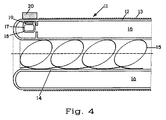
- the excimer radiator 11 consists of an outer quartz glass tube 12, which is covered on its outer surface with a metallic mesh 13, which forms the outer electrode of the excimer radiator 11 and an inner quartz glass tube 14, which is arranged coaxially with the outer quartz glass tube 12 and on the inner wall of which Metallic spiral 15 is present, which forms the inner electrode of the excimer lamp 11.
- the annular gap between the outer quartz glass tube 12 and the inner quartz glass tube 14 corresponds to the discharge space 16 of the excimer radiator 11.
- the volume of the discharge space 16 is approximately 470 cm 3 .
- the power density of the spotlight is 30 watts per cm of the illuminated spot length.
- a quartz glass capsule 17 filled with chlorine is arranged in the discharge space 16.
- the wall of the capsule 17 is scored and in this way provided with a predetermined breaking point 18.
- the chlorine content of the capsule 17 is set such that after breaking the capsule 17, the chlorine content in the discharge space 16 is increased, namely by 1 ⁇ 10 -11 mol / cm 3 and per cm 2 of the inner surface of the discharge space 16.
- a metal part 19 is embedded in the wall of the capsule 17 and shielded from the discharge space 16.
- the metal part 19 together with the capsule 17 is held in an upper position by means of a magnet 20. If the capsule 17 is dropped from this position by removing or switching off the magnet 20, it breaks and the chlorine contained therein escapes into the discharge space 16. In this way, the chlorine content in the discharge space 16 can be regenerated.
- the intensity of a characteristic emission wavelength of the excimer radiator 11 is measured by means of a UV sensor. If the intensity falls below a lower limit, this is indicated optically and the magnet 20 is then removed.
- the magnet 20 is designed as an electromagnet, the magnet 20 is automatically switched off when the intensity falls below a lower limit and the chlorine is thereby released from the capsule 17 into the discharge space 16.
Landscapes
- Vessels And Coating Films For Discharge Lamps (AREA)
- Discharge Lamp (AREA)
- Discharge Lamps And Accessories Thereof (AREA)
- Lasers (AREA)
- Treatments Of Macromolecular Shaped Articles (AREA)
Applications Claiming Priority (2)
| Application Number | Priority Date | Filing Date | Title |
|---|---|---|---|
| DE19613502A DE19613502C2 (de) | 1996-04-04 | 1996-04-04 | Langlebiger Excimerstrahler und Verfahren zu seiner Herstellung |
| DE19613502 | 1996-04-04 |
Publications (3)
| Publication Number | Publication Date |
|---|---|
| EP0800201A2 true EP0800201A2 (fr) | 1997-10-08 |
| EP0800201A3 EP0800201A3 (fr) | 1998-01-28 |
| EP0800201B1 EP0800201B1 (fr) | 2000-09-20 |
Family
ID=7790468
Family Applications (1)
| Application Number | Title | Priority Date | Filing Date |
|---|---|---|---|
| EP97105297A Expired - Lifetime EP0800201B1 (fr) | 1996-04-04 | 1997-03-27 | Source de rayonnement à excimer à longue durée de vie, son procédé de fabrication et procédé pour l'allongement de sa durée de vie ainsi qu'un dispositif pour la mise en oeuvre de ce dernier procédé |
Country Status (4)
| Country | Link |
|---|---|
| US (1) | US5889367A (fr) |
| EP (1) | EP0800201B1 (fr) |
| JP (1) | JP4004590B2 (fr) |
| DE (2) | DE19613502C2 (fr) |
Cited By (3)
| Publication number | Priority date | Publication date | Assignee | Title |
|---|---|---|---|---|
| EP1009016A1 (fr) * | 1998-12-08 | 2000-06-14 | Heraeus Noblelight GmbH | Lampe à décharge |
| WO2006086942A3 (fr) * | 2005-02-14 | 2007-09-20 | Patent Treuhand Ges Fuer Elektrische Gluehlampen Mbh | Lampe a decharge a barriere dielectrique ayant une configuration a double tube |
| WO2012110074A1 (fr) * | 2011-02-14 | 2012-08-23 | Osram Ag | Lampe à décharge à haute intensité dotée d'une aide à l'amorçage halogénée |
Families Citing this family (24)
| Publication number | Priority date | Publication date | Assignee | Title |
|---|---|---|---|---|
| US5993278A (en) * | 1998-02-27 | 1999-11-30 | The Regents Of The University Of California | Passivation of quartz for halogen-containing light sources |
| DE19912544B4 (de) * | 1999-03-19 | 2007-01-18 | Heraeus Noblelight Gmbh | Infrarotstrahler und Verfahren zur Erwärmung eines Behandlungsgutes |
| DE10024963A1 (de) | 2000-05-22 | 2001-12-13 | Heraeus Noblelight Gmbh | Strahlungsanordnung sowie deren Verwendung und Verfahren zur Behandlung von Oberflächen |
| JP3563373B2 (ja) * | 2001-06-14 | 2004-09-08 | 株式会社日本フォトサイエンス | 放電灯および紫外線照射装置並びにその運用方法 |
| RU2239911C1 (ru) * | 2003-04-21 | 2004-11-10 | Институт сильноточной электроники СО РАН | Источник излучения |
| RU2258975C1 (ru) * | 2003-12-22 | 2005-08-20 | Институт сильноточной электроники СО РАН | Источник излучения |
| US20050199484A1 (en) * | 2004-02-10 | 2005-09-15 | Franek Olstowski | Ozone generator with dual dielectric barrier discharge and methods for using same |
| EP1769525B1 (fr) * | 2004-07-09 | 2010-03-03 | Philips Intellectual Property & Standards GmbH | Lampe a decharge a barriere dielectrique avec moyen multifonctionnel integre |
| WO2006017644A2 (fr) * | 2004-08-03 | 2006-02-16 | Franek Olstowski | Commande amelioree d'intensite de lumiere en boucle fermee et procede associe d'application de fluorescence |
| RU2291516C2 (ru) * | 2005-03-18 | 2007-01-10 | Институт сильноточной электроники СО РАН | Лампа вакуумная ультрафиолетового диапазона спектра |
| RU2292601C1 (ru) * | 2005-06-06 | 2007-01-27 | Военно-космическая академия им. А.Ф. Можайского | Установка для исследования электромагнитного поля |
| WO2007071074A1 (fr) * | 2005-12-21 | 2007-06-28 | Trojan Technologies Inc. | Ensemble lampe a rayonnement a excimere, module de source et systeme de traitement de liquide contenant le module |
| JP4952472B2 (ja) * | 2007-09-20 | 2012-06-13 | ウシオ電機株式会社 | エキシマランプおよびエキシマランプの製造方法 |
| RU2385515C2 (ru) * | 2007-11-20 | 2010-03-27 | Галина Аркадьевна Волкова | Лампа барьерного разряда |
| JP5302637B2 (ja) * | 2008-11-17 | 2013-10-02 | 株式会社オーク製作所 | 放電ランプ |
| US8164263B2 (en) * | 2009-04-10 | 2012-04-24 | Ushio Denki Kabushiki Kaisha | Excimer discharge lamp |
| JP4752943B2 (ja) * | 2009-04-10 | 2011-08-17 | ウシオ電機株式会社 | エキシマ放電ランプ |
| RU2398310C1 (ru) * | 2009-08-03 | 2010-08-27 | Учреждение Российской академии наук Институт сильноточной электроники Сибирского отделения РАН | Газоразрядный источник излучения (варианты) |
| JP2014049280A (ja) * | 2012-08-31 | 2014-03-17 | Ushio Inc | エキシマランプ |
| US8754576B2 (en) | 2012-09-28 | 2014-06-17 | Elwha Llc | Low pressure lamp using non-mercury materials |
| RU2546144C2 (ru) * | 2013-07-25 | 2015-04-10 | Федеральное государственное бюджетное учреждение науки Институт сильноточной электроники Сибирского отделения Россиийской академии наук, (ИСЭ СО РАН) | Источник излучения |
| RU200241U1 (ru) * | 2019-12-19 | 2020-10-14 | Федеральное государственное бюджетное учреждение науки Институт сильноточной электроники Сибирского отделения Российской академии наук, (ИСЭ СО РАН) | Источник излучения |
| JP6950799B1 (ja) * | 2020-08-28 | 2021-10-13 | ウシオ電機株式会社 | エキシマランプ |
| JP6948606B1 (ja) | 2020-08-28 | 2021-10-13 | ウシオ電機株式会社 | エキシマランプ及び光照射装置 |
Family Cites Families (17)
| Publication number | Priority date | Publication date | Assignee | Title |
|---|---|---|---|---|
| US5173638A (en) * | 1986-07-22 | 1992-12-22 | Bbc Brown, Boveri Ag | High-power radiator |
| CH675178A5 (fr) * | 1987-10-23 | 1990-08-31 | Bbc Brown Boveri & Cie | |
| DE58908551D1 (de) * | 1988-06-03 | 1994-12-01 | Forschungszentrum Juelich Gmbh | Metallhalogenid-Entladungslampen. |
| US4870323A (en) * | 1988-07-13 | 1989-09-26 | Gte Products Corporation | Method of dispensing mercury into an arc discharge lamp |
| CH676168A5 (fr) * | 1988-10-10 | 1990-12-14 | Asea Brown Boveri | |
| JPH02112292A (ja) * | 1988-10-20 | 1990-04-24 | Mitsubishi Electric Corp | ハロゲンガスレーザのガス制御装置 |
| DE3907277A1 (de) * | 1989-03-07 | 1990-09-20 | Patent Treuhand Ges Fuer Elektrische Gluehlampen Mbh | Quecksilberniederdruckentladungslampe |
| US4977573A (en) * | 1989-03-09 | 1990-12-11 | Questek, Inc. | Excimer laser output control device |
| DE3910809C2 (de) * | 1989-04-04 | 1994-02-17 | Werner Reinig | Anordnung zum Gleichstrombetrieb einer Leuchtstofflampe |
| US5062116A (en) * | 1990-05-17 | 1991-10-29 | Potomac Photonics, Inc. | Halogen-compatible high-frequency discharge apparatus |
| JP3076392B2 (ja) * | 1991-03-29 | 2000-08-14 | 株式会社東芝 | エキシマレーザ装置の不動態化処理方法 |
| DE59105798D1 (de) * | 1991-04-15 | 1995-07-27 | Heraeus Noblelight Gmbh | Bestrahlungseinrichtung. |
| EP0521553B1 (fr) * | 1991-07-01 | 1996-04-24 | Koninklijke Philips Electronics N.V. | Lampe à décharge luminescente à haute pression |
| DE4140497C2 (de) * | 1991-12-09 | 1996-05-02 | Heraeus Noblelight Gmbh | Hochleistungsstrahler |
| DE4222130C2 (de) * | 1992-07-06 | 1995-12-14 | Heraeus Noblelight Gmbh | Hochleistungsstrahler |
| EP0607960B2 (fr) * | 1993-01-20 | 2001-05-16 | Ushiodenki Kabushiki Kaisha | Lampe à décharge avec barrière diélectrique |
| EP0641015B1 (fr) * | 1993-08-03 | 1997-04-16 | Ushiodenki Kabushiki Kaisha | Lampe à décharge à cadmium |
-
1996
- 1996-04-04 DE DE19613502A patent/DE19613502C2/de not_active Expired - Fee Related
-
1997
- 1997-03-27 DE DE59702367T patent/DE59702367D1/de not_active Expired - Lifetime
- 1997-03-27 EP EP97105297A patent/EP0800201B1/fr not_active Expired - Lifetime
- 1997-04-02 JP JP08346997A patent/JP4004590B2/ja not_active Expired - Lifetime
- 1997-04-03 US US08/832,281 patent/US5889367A/en not_active Expired - Lifetime
Cited By (3)
| Publication number | Priority date | Publication date | Assignee | Title |
|---|---|---|---|---|
| EP1009016A1 (fr) * | 1998-12-08 | 2000-06-14 | Heraeus Noblelight GmbH | Lampe à décharge |
| WO2006086942A3 (fr) * | 2005-02-14 | 2007-09-20 | Patent Treuhand Ges Fuer Elektrische Gluehlampen Mbh | Lampe a decharge a barriere dielectrique ayant une configuration a double tube |
| WO2012110074A1 (fr) * | 2011-02-14 | 2012-08-23 | Osram Ag | Lampe à décharge à haute intensité dotée d'une aide à l'amorçage halogénée |
Also Published As
| Publication number | Publication date |
|---|---|
| DE19613502A1 (de) | 1997-10-09 |
| DE19613502C2 (de) | 1998-07-09 |
| DE59702367D1 (de) | 2000-10-26 |
| EP0800201A3 (fr) | 1998-01-28 |
| JPH1051081A (ja) | 1998-02-20 |
| US5889367A (en) | 1999-03-30 |
| EP0800201B1 (fr) | 2000-09-20 |
| JP4004590B2 (ja) | 2007-11-07 |
Similar Documents
| Publication | Publication Date | Title |
|---|---|---|
| EP0800201B1 (fr) | Source de rayonnement à excimer à longue durée de vie, son procédé de fabrication et procédé pour l'allongement de sa durée de vie ainsi qu'un dispositif pour la mise en oeuvre de ce dernier procédé | |
| DE69911091T2 (de) | Entladungslampe und Verfahren zu deren Herstellung | |
| DE69409677T3 (de) | Entladungslampe mit dielektrischer Sperrschicht | |
| DE69804192T2 (de) | Hochdruckentladungslampe mit uv-verstärker | |
| EP0782871A2 (fr) | Procédé et dispositif d'irradiation ultra-violet destiné au rayonnement corporelque son emploi | |
| DE68911954T2 (de) | Elektrische Lampe. | |
| DE3038993C2 (de) | Metalldampfentladungslampe | |
| DE69402641T2 (de) | Cadmiumentladungslampe | |
| DE2835575C2 (de) | Leuchtstoff für eine Niederdruckquecksilberdampfentladungslampe | |
| DE69504466T2 (de) | Niederdruckquecksilberdampfentladungslampe | |
| DE830984C (de) | Entladungslampe zur Erzeugung von Blitzlicht hoher Intensitaet und Verfahren zum Betrieb der Lampe | |
| EP0461634B1 (fr) | Procédé de fabrication d'une source lumineuse à décharge dans un gaz et tube de décharge gazeuse | |
| DE69807266T2 (de) | Kurzbogen-Quecksilberlampe | |
| DE60033299T2 (de) | Hochdruckentladungslampe | |
| DE69926706T2 (de) | Niederdruckquecksilberdampfeentladungslampe | |
| DE3123604C2 (de) | Metalldampf-Hochdruckentladungslampe | |
| DE69915181T2 (de) | Quarzglas, optisches Element und gegen ultraviolette und radioaktive Strahlung resistente faseroptische Vorrichtung, und Herstellungsverfahren dafür | |
| DE2100245B2 (fr) | ||
| DE2519014A1 (de) | Hochdruckentladungslampe | |
| DE69303070T2 (de) | Hochdruckentladungslampe | |
| DE3123605A1 (de) | Metalldampf-hochdruckentladungslampe | |
| EP0547374A1 (fr) | Lampe à décharge dans les gaz étanche | |
| DE19737920A1 (de) | Niederdruck-Gasentladungslampe mit erhöhter Lebensdauer | |
| WO2003075315A2 (fr) | Source de lumiere et procede de regeneration d'une source de lumiere | |
| DE2952022A1 (de) | Stabilisierte hochleistungs-entladungslampe |
Legal Events
| Date | Code | Title | Description |
|---|---|---|---|
| PUAI | Public reference made under article 153(3) epc to a published international application that has entered the european phase |
Free format text: ORIGINAL CODE: 0009012 |
|
| 17P | Request for examination filed |
Effective date: 19970416 |
|
| AK | Designated contracting states |
Kind code of ref document: A2 Designated state(s): CH DE GB IT LI NL |
|
| PUAL | Search report despatched |
Free format text: ORIGINAL CODE: 0009013 |
|
| AK | Designated contracting states |
Kind code of ref document: A3 Designated state(s): CH DE GB IT LI NL |
|
| GRAG | Despatch of communication of intention to grant |
Free format text: ORIGINAL CODE: EPIDOS AGRA |
|
| RTI1 | Title (correction) |
Free format text: LONG-LIFE EXCIMER RADIATOR, PROCESSES FOR MANUFACTURING AND FOR INCREASING THE LIFE OF SUCH A RADIATOR AND DEVICE FOR IMPLEMENTING SAID LAST PROCESS |
|
| GRAG | Despatch of communication of intention to grant |
Free format text: ORIGINAL CODE: EPIDOS AGRA |
|
| GRAH | Despatch of communication of intention to grant a patent |
Free format text: ORIGINAL CODE: EPIDOS IGRA |
|
| 17Q | First examination report despatched |
Effective date: 20000207 |
|
| GRAH | Despatch of communication of intention to grant a patent |
Free format text: ORIGINAL CODE: EPIDOS IGRA |
|
| GRAA | (expected) grant |
Free format text: ORIGINAL CODE: 0009210 |
|
| AK | Designated contracting states |
Kind code of ref document: B1 Designated state(s): CH DE GB IT LI NL |
|
| REG | Reference to a national code |
Ref country code: CH Ref legal event code: EP |
|
| REG | Reference to a national code |
Ref country code: CH Ref legal event code: NV Representative=s name: KIRKER & CIE SA |
|
| GBT | Gb: translation of ep patent filed (gb section 77(6)(a)/1977) |
Effective date: 20000921 |
|
| REF | Corresponds to: |
Ref document number: 59702367 Country of ref document: DE Date of ref document: 20001026 |
|
| ITF | It: translation for a ep patent filed | ||
| EN | Fr: translation not filed | ||
| PLBE | No opposition filed within time limit |
Free format text: ORIGINAL CODE: 0009261 |
|
| STAA | Information on the status of an ep patent application or granted ep patent |
Free format text: STATUS: NO OPPOSITION FILED WITHIN TIME LIMIT |
|
| 26N | No opposition filed | ||
| REG | Reference to a national code |
Ref country code: GB Ref legal event code: IF02 |
|
| PGFP | Annual fee paid to national office [announced via postgrant information from national office to epo] |
Ref country code: CH Payment date: 20160323 Year of fee payment: 20 Ref country code: NL Payment date: 20160321 Year of fee payment: 20 Ref country code: DE Payment date: 20160321 Year of fee payment: 20 |
|
| PGFP | Annual fee paid to national office [announced via postgrant information from national office to epo] |
Ref country code: GB Payment date: 20160321 Year of fee payment: 20 |
|
| PGFP | Annual fee paid to national office [announced via postgrant information from national office to epo] |
Ref country code: IT Payment date: 20160324 Year of fee payment: 20 |
|
| REG | Reference to a national code |
Ref country code: DE Ref legal event code: R071 Ref document number: 59702367 Country of ref document: DE |
|
| REG | Reference to a national code |
Ref country code: NL Ref legal event code: MK Effective date: 20170326 |
|
| REG | Reference to a national code |
Ref country code: CH Ref legal event code: PL |
|
| REG | Reference to a national code |
Ref country code: GB Ref legal event code: PE20 Expiry date: 20170326 |
|
| PG25 | Lapsed in a contracting state [announced via postgrant information from national office to epo] |
Ref country code: GB Free format text: LAPSE BECAUSE OF EXPIRATION OF PROTECTION Effective date: 20170326 |