EP0800236A2 - Construction de connexion pour éléments tubulaires - Google Patents
Construction de connexion pour éléments tubulaires Download PDFInfo
- Publication number
- EP0800236A2 EP0800236A2 EP97105642A EP97105642A EP0800236A2 EP 0800236 A2 EP0800236 A2 EP 0800236A2 EP 97105642 A EP97105642 A EP 97105642A EP 97105642 A EP97105642 A EP 97105642A EP 0800236 A2 EP0800236 A2 EP 0800236A2
- Authority
- EP
- European Patent Office
- Prior art keywords
- tubular member
- side tubular
- end portion
- corrugate tube
- fitting end
- Prior art date
- Legal status (The legal status is an assumption and is not a legal conclusion. Google has not performed a legal analysis and makes no representation as to the accuracy of the status listed.)
- Withdrawn
Links
Images


Classifications
-
- H—ELECTRICITY
- H01—ELECTRIC ELEMENTS
- H01R—ELECTRICALLY-CONDUCTIVE CONNECTIONS; STRUCTURAL ASSOCIATIONS OF A PLURALITY OF MUTUALLY-INSULATED ELECTRICAL CONNECTING ELEMENTS; COUPLING DEVICES; CURRENT COLLECTORS
- H01R13/00—Details of coupling devices of the kinds covered by groups H01R12/70 or H01R24/00 - H01R33/00
- H01R13/56—Means for preventing chafing or fracture of flexible leads at outlet from coupling part
- H01R13/562—Bending-relieving
-
- Y—GENERAL TAGGING OF NEW TECHNOLOGICAL DEVELOPMENTS; GENERAL TAGGING OF CROSS-SECTIONAL TECHNOLOGIES SPANNING OVER SEVERAL SECTIONS OF THE IPC; TECHNICAL SUBJECTS COVERED BY FORMER USPC CROSS-REFERENCE ART COLLECTIONS [XRACs] AND DIGESTS
- Y10—TECHNICAL SUBJECTS COVERED BY FORMER USPC
- Y10S—TECHNICAL SUBJECTS COVERED BY FORMER USPC CROSS-REFERENCE ART COLLECTIONS [XRACs] AND DIGESTS
- Y10S285/00—Pipe joints or couplings
- Y10S285/903—Corrugated
Definitions
- the present invention relates to a connection construction for tubular members for connecting an inserting side tubular member with a receiving side tubular member having a deformable flexible portion by fitting or inserting the inserting side tubular member into the receiving side tubular member.
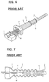
- a rubber boot 3 is mounted between the connector 1 and the corrugate tube 2 as shown in FIG. 6.
- the rubber boot 3 includes a connector connection portion 7 whose width increases toward its open end, a bellowslike flexible portion 4, and a fitting end portion 5 for the connection with the corrugate tube 2.
- the wires extending from the connector 1 are protected by the connector connection portion 7.
- the leading end of the corrugate tube 2 is fitted into the fitting end portion 5 during the connection of the rubber boot 3 and the corrugate tube 2.
- the leading end of the corrugate tube 2 may enter the flexible portion 4, passing the fitting end portion 5 as shown in FIG. 7. If the rubber boot 3 and the corrugate tube 2 are connected in this state, a smooth deformation of the flexible portion 4 may be hindered by the difficulty of the corrugate tube 2 to be deformed in the case that an attempt is made to arrange the wiring harness while bending the wires W at the flexible portion 4.
- the present invention was developed in view of the above problem and an object thereof is to provided a connection construction, which ensures a smooth deformation of a deformable portion of the connection construction.
- connection construction for connecting an inserting side tubular member with a receiving side tubular member having a substantially deformable flexible portion and a fitting or connecting end portion continuous or integral or unitary with the flexible portion by fitting the inserting side tubular member into the fitting end portion, comprising stopper means for restricting the insertion or fitting of the inserting side tubular member into the receiving side tubular member to a predetermined or predeterminable insertion length.
- connection construction for connecting an inserting side tubular member with a receiving side tubular member having a deformable flexible portion and a fitting end portion continuous with the flexible portion by fitting the inserting side tubular member into the fitting end portion, comprising stopper means for preventing the entry of the inserting side tubular member into the flexible portion beyond the fitting end portion.
- any further insertion of the inserting side tubular member is restricted by the stopper means, thereby preventing the entry of the inserting side tubular member into the flexible portion.
- the stopper means prevents the entry of the inserting side tubular member into the flexible portion beyond the fitting end portion.
- the stopper means comprises at least one projection so as to project from the inner surface of the fitting end portion and with which the inserting side tubular member comes or can come into contact.
- the at least one projection is integrally or unitarily formed with the fitting end portion.
- the stopper means is constructed by the projections integrally or unitarily formed with the inner surface of the fitting end portion, the receiving side tubular member can be produced with better efficiency and at a reduced cost as compared to the case where the stopper means is a member separate from the receiving side tubular member.
- the projections are provided in a plurality of circumferentially spaced positions, being preferably equally circumferentially spaced.
- an insertion member in contact with the inner surface of the receiving side tubular member can pass where the projections are not provided without being caught by the projections. Accordingly, unlike the case where the projection extends over the entire circumference, the insertion of the insertion member is unlikely to be hindered by the insertion member getting caught by the projections. Thus, the insertion member can easily and efficiently be inserted.
- each projection is formed with a tapered or slanted guide surface which is smoothly continuous with the inner surface of the fitting end portion.
- the insertion member having inserted into the receiving side tubular member moves toward the projections, it can pass the projections without being caught by the presence of the guide surfaces.
- the insertion member can more easily and efficiently be inserted.
- the stopper means is formed such that it comes into contact with the receiving side tubular member, in particular with a jaw portion or the edge of the receiving side tubular member.
- the stopper means comprises a ring member which projects from the outer surface of the inserting side tubular member.
- the stopper means is constructed by the ring member provided on the outer surface of the inserting side tubular member, the contact of the ring member with the fitting end portion can be visually confirmed. Accordingly, an insufficient connection resulting from an excessively short fitting length of the inserting side tubular member into the receiving side tubular member can be prevented.
- the receiving side tubular member is provided with one or more slits, being in particular equally circumferentially spaced, preferably for securing the inserting side tubular member to the receiving side tubular member by reducing at least partially the circumference of the receiving side tubular member.
- the circumference of the receiving side tubular member is reduced by applying fastening means, in particular by wounding tape or fitting or inserting a clamp, to the receiving side tubular member.
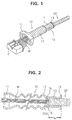
- FIGS. 1 to 3 a first embodiment of the invention is described with reference to FIGS. 1 to 3.
- Terminals (not shown) secured to ends of a plurality of wires W are mounted in a connector C, and the wires W extend from the rear side of the connector C to form a wiring harness.
- a rubber boot (receiving side tubular member as an element of the invention) 10 and a corrugate tube 20 (inserting side tubular member as an element of the invention) are fitted or fittable on or inserted or insertable over this bundle of wires W so as to protect the terminals from deposition of waterdrops or like undesirable occurrence.
- the corrugate tube 20 has a bellowslike shape, and a cut or recess (not shown) is made over its entire length along its longitudinal direction.
- the corrugate tube 20 is cut to a specified length so as to conform to the length of the wires W to be arranged.
- the corrugate tube 20 is fitted around the wires W by opening the cut.
- the corrugate tube 20 is made e.g. of a resin material and relatively hard to be deformed. Accordingly, the wires W contained in the corrugate tube 20 are arranged while being substantially held in a desired configuration.
- a leading end 20A of the corrugate tube 20 is connected with a fitting end portion 13 of the rubber boot 10 to be described later by being closely fitted or inserted into the fitting end portion 13.
- the rubber boot 10 is such that a connector connection portion 11, a flexible portion 12 and the fitting end portion 13 are continuously formed in this order from its leading end and has, as a whole, such a tubular shape as to permit the insertion of the wires W.
- the connector connection portion 11 is shaped such that its width substantially increases toward the leading end, and a preferably rectangular opening formed at the leading end thereof is fitted on the connector C to connect the rubber boot 10 with the connector C.
- the shape of the opening is adapted to the outer shape of the connector C.
- the flexible portion 12 has a bellowslike shape and is easily deformable. The deformability of the flexible portion 12 allows the wires W to be bent for the arrangement.
- the fitting end portion 13 has, as a whole, a tubular shape and is formed with two slits 14 extending from its rear end to its front end. Into the fitting end portion 13 is closely fitted the leading end 20A of the corrugate tube 20. The inner diameter of the fitting end portion 13 is substantially equal to the smallest inner diameter of the flexible portion 12.
- a jaw portion 15 is formed at a rear edge of the fitting end portion 13.
- the rubber boot 10 is provided with a stopper means for restricting the fitting or insertion length L of the corrugate tube 20.
- the stopper means according to this embodiment is constructed by e.g. four projections 16 integrally or unitarily formed with the rubber boot 10.
- the respective projections 16 have a preferably rounded or semispherical shape; project inward in the front end positions (at a boundary with the flexible portion 12) of the inner surface of the fitting end portion 13 with respect to the longitudinal direction as shown in FIG. 2; and are circumferentially arranged, in particular at even intervals of substantially 90° as shown in FIG. 3.
- the wires W before the connection with the connector C are inserted into the rubber boot 10 from its rear side, i.e. from the fitting end portion 13 through the flexible portion 12 and the connector connection portion 11. At this time, even if the terminals connected at the leading ends of the wires W move in contact with the inner surface of the fitting end portion 13, they can pass through the smooth surface areas between the projections 16. Accordingly, the insertion of the wires W is not obstructed by the projections 16.
- the rubber boot 10 is fitted on the connector C. It should be appreciated that the rubber boot 10 may be fitted on the connector C after the corrugate tube 20 is connected with the rubber boot 10. Portions of the wires W extending rearward from the rubber boot 10 are covered by the corrugate tube 20.
- the corrugate tube 20 is connected with the rubber boot 10. During this connection, the leading end 20A of the corrugate tube 20 is fitted into the fitting end portion 13. However, no consideration is necessary as to whether or not the fitting length of the leading end 20A is excessively long. More specifically, as the corrugate tube 20 is inserted, the leading end 20A thereof comes into contact with the projections 16 before entering the flexible portion 12, with the result that the undesired entry of the leading end 20A into the flexible portion 12 can be prevented. In the case that the corrugate tube 20 is insufficiently fitted into the fitting end portion 13, the position of the leading edge of the corrugate tube 20 can be visually confirmed through the slits 14. Accordingly, there is no likelihood that the corrugate tube 20 is left insufficiently fitted.
- tape T is wound around the fitting end portion 13, thereby fastening the corrugate tube 20 to the fitting end portion 13 while narrowing the width of the slits 14.
- a clamp or clip may be fitted or clamped on or around the fitting end portion 13.
- the clamp may be inserted into one or more recesses or openings (not shown) formed in the end fitting portion 13, in particular so as to be at least partially in contact with the corrugate tube 20.
- the tape T and/or the clamp thus form securing or fastening means.
- the corrugate tube 20 is not located in the flexible portion 12 when the rubber boot 10 and the corrugate tube 20 are connected, there is no likelihood that the easy and smooth deformation of the flexible portion 12 is hindered by the difficulty of the corrugate tube 20 to be deformed when the wires W are arranged while being bent at a small radius of curvature in the vicinity of the connector C. Thus, the wires can easily bent for the arrangement.
- the stopper means is constructed by the projections 16 integrally or unitarily formed with the rubber boot 10, the rubber boot 10 can be produced with better efficiency and at a reduced cost as compared with the case where a separately formed stopper means is mounted on the rubber 10.
- the terminals in contact with the inner surface of the fitting end portion 13 can move to the flexible portion 12 without getting caught by the projections 16 during the insertion of the wires W into the rubber boot 10.
- the wires W can be easily and smoothly inserted through the rubber boot 10.
- the second embodiment differs from the first embodiment in the shape of the projections. Since the other construction is same or similar as the first embodiment, no description is given on the construction, action and effect thereof by identifying it by the same reference numerals.
- Each projection 17 in this embodiment has a right, substantially triangular cross section and is formed with a tapered or slanted or inclined guide surface 17A smoothly continuous with the inner surface of the fitting end portion 13. Accordingly, while wires (not shown in FIG. 4) are inserted into the rubber boot 10 through an opening at the rear end of the end fitting portion 13 from terminals connected therewith, even if the terminals move toward the projections 17 while sliding in contact with the inner surface of the fitting end portion 13, the terminals smoothly move along the guide surfaces 17A without getting caught and pass the projections 17 while being in sliding contact with the guide surfaces 17A. Therefore, the wires can be easily and smoothly inserted through the rubber boot 10.
- the third embodiment differs from the first embodiment in the construction of the stopper means. Since the other construction is same or similar as the first embodiment, no description is given on the construction, action and effect thereof by identifying it by the same reference numerals.
- the stopper means of this embodiment is constructed by a ring member (stopper means as an element of the present invention) 30 formed separately from the rubber boot 10 and the corrugate tube 20.
- the ring member 30 is fitted in a groove 21 of a bellows on the outer surface of the corrugate tube 20 and is secured by adhesive or the like so as not to come off.
- the groove 21 in which the ring member 30 is fitted is so determined that the length between the groove 21 and the leading edge of the corrugate tube 20 is substantially not longer than the length of the fitting end portion 13.
- the ring member 30 is set in position by being fitted to the leading edge of the corrugate tube 20 and slid along the longitudinal direction by contractively deforming the corrugate tube 20. By displacing or setting the ring 30 appropriately on the corrugate tube 20 the insertion or fitting length L of the corrugate tube into the fitting end portion 13 can be predetermined or apropriately set.
- the ring member 30 comes into contact with the jaw portion 15 at the rear end of the fitting end portion 13, preferably before the leading end 20A of the corrugate tube 20 enters the flexible portion 12, thereby hindering any further entry of the corrugate tube 20 into the fitting end portion 13. This prevents the entry of the corrugate tube 20 into the flexible portion 12 caused by an excessive insertion.
- the position of the ring member 30 away from the jaw portion 15 can be visually confirmed. Accordingly, there is no likelihood that the corrugate tube 20 is left insufficiently fitted.
Landscapes
- Details Of Indoor Wiring (AREA)
- Joints That Cut Off Fluids, And Hose Joints (AREA)
- Mutual Connection Of Rods And Tubes (AREA)
- Details Of Connecting Devices For Male And Female Coupling (AREA)
Applications Claiming Priority (2)
| Application Number | Priority Date | Filing Date | Title |
|---|---|---|---|
| JP84244/96 | 1996-04-05 | ||
| JP08424496A JP3178335B2 (ja) | 1996-04-05 | 1996-04-05 | 筒状部材の接続構造 |
Publications (2)
| Publication Number | Publication Date |
|---|---|
| EP0800236A2 true EP0800236A2 (fr) | 1997-10-08 |
| EP0800236A3 EP0800236A3 (fr) | 1998-10-14 |
Family
ID=13825057
Family Applications (1)
| Application Number | Title | Priority Date | Filing Date |
|---|---|---|---|
| EP97105642A Withdrawn EP0800236A3 (fr) | 1996-04-05 | 1997-04-04 | Construction de connexion pour éléments tubulaires |
Country Status (4)
| Country | Link |
|---|---|
| US (1) | US5876069A (fr) |
| EP (1) | EP0800236A3 (fr) |
| JP (1) | JP3178335B2 (fr) |
| CN (1) | CN1051649C (fr) |
Cited By (1)
| Publication number | Priority date | Publication date | Assignee | Title |
|---|---|---|---|---|
| CN103527585A (zh) * | 2013-09-26 | 2014-01-22 | 中国船舶重工集团公司第七一〇研究所 | 伸缩杆保护装置 |
Families Citing this family (20)
| Publication number | Priority date | Publication date | Assignee | Title |
|---|---|---|---|---|
| CN1075619C (zh) * | 1996-09-03 | 2001-11-28 | 住友电装株式会社 | 一种波纹管、一种自动导线装载方法和装置 |
| EP1033799B1 (fr) * | 1999-03-02 | 2004-06-02 | Richco Italia S.r.l. | Dispositif pour insérer des fils ou des tuyaux dans une gaine tubulaire flexible pourvue d'arêtes qui se chevauchent et qui sont ouvrables |
| US6843678B2 (en) * | 2002-04-22 | 2005-01-18 | Dekko Technologies, Inc. | Press fit electrical connector assembly |
| JP4541287B2 (ja) * | 2005-12-05 | 2010-09-08 | 矢崎総業株式会社 | ハーネス保護チューブの長さ調整構造とそれを備えた給電装置 |
| JP5239833B2 (ja) * | 2008-12-24 | 2013-07-17 | トヨタ自動車株式会社 | 回転電機ステータへの温度センサの取付構造および取付方法 |
| KR101744997B1 (ko) * | 2011-08-25 | 2017-06-09 | 현대자동차주식회사 | 자동차의 실드 도전체 |
| KR20140014591A (ko) * | 2012-07-25 | 2014-02-06 | 현대모비스 주식회사 | 와이어 기밀처리부재 및 이를 적용한 컨버터 모듈 |
| JP2014063716A (ja) * | 2012-08-31 | 2014-04-10 | Junkosha Inc | ケーブル |
| JP6010817B2 (ja) * | 2012-09-03 | 2016-10-19 | 矢崎総業株式会社 | ワイヤハーネス同士の合体構造 |
| JP2014136190A (ja) * | 2013-01-17 | 2014-07-28 | Nsp Ks Corp | 回転装置によって回転駆動されるケレン器 |
| CN103531291A (zh) * | 2013-10-15 | 2014-01-22 | 安徽巨一自动化装备有限公司 | 电动汽车电机三相线布线结构 |
| JP6570279B2 (ja) * | 2015-03-16 | 2019-09-04 | ダイハツ工業株式会社 | ハーネス規制装置 |
| JP6508015B2 (ja) * | 2015-11-20 | 2019-05-08 | 住友電装株式会社 | ワイヤーハーネス、電線保護部材及び電線ホルダ |
| JP6901365B2 (ja) * | 2017-09-29 | 2021-07-14 | プライムアースEvエナジー株式会社 | コネクタカバー及びコネクタアッシー |
| JP7091858B2 (ja) * | 2018-06-11 | 2022-06-28 | トヨタ自動車株式会社 | ケーブル接続構造 |
| CN109818201A (zh) * | 2019-03-25 | 2019-05-28 | 浙江欣海船舶设计研究院有限公司 | 一种江海直达船岸电系统配件装置 |
| JP7336389B2 (ja) * | 2020-01-07 | 2023-08-31 | 株式会社ミクニ | 配線カバー及び電気ユニット |
| JP7491062B2 (ja) * | 2020-06-03 | 2024-05-28 | 住友電装株式会社 | 配線部材 |
| CN111817225B (zh) * | 2020-07-03 | 2022-02-08 | 江苏科信光电科技有限公司 | 一种可多节折弯固定的仿蜈蚣型线缆铺设管道 |
| JP2025072195A (ja) * | 2023-10-24 | 2025-05-09 | 本田技研工業株式会社 | 保護部材 |
Family Cites Families (14)
| Publication number | Priority date | Publication date | Assignee | Title |
|---|---|---|---|---|
| US18116A (en) * | 1857-09-01 | Pipe-coupling | ||
| CA881982A (en) * | 1971-09-28 | Thomas Carl | Pipe-jointing sleeve | |
| US1057763A (en) * | 1911-10-30 | 1913-04-01 | Mueller Mfg Co H | Method of coupling telescopic pipes. |
| US2125485A (en) * | 1936-02-28 | 1938-08-02 | George D Ladd | Electrical connecter |
| US2275800A (en) * | 1939-08-17 | 1942-03-10 | Belden Mfg Co | Electrical connector |
| US3873137A (en) * | 1973-09-19 | 1975-03-25 | Seiichi Yamaguchi | Bellows-type joint assembly |
| US4647135A (en) * | 1985-07-10 | 1987-03-03 | Whirlwind Music Distributors, Inc. | Plug for audio device |
| US4810008A (en) | 1987-06-22 | 1989-03-07 | Scott Brodie | Method and apparatus for repairing lawn sprinkler systems |
| JPH01103283A (ja) * | 1987-10-14 | 1989-04-20 | Hitachi Ltd | 関節型マニピュレータ |
| JPH0342302Y2 (fr) * | 1987-11-10 | 1991-09-04 | ||
| US4913473A (en) * | 1987-11-16 | 1990-04-03 | Bonnema Eldon G | Large diameter double-walled plastic pipe |
| DE3914936A1 (de) * | 1989-05-06 | 1990-11-08 | Messerschmitt Boelkow Blohm | Endgehaeuse fuer mehrpolige elektrische steckverbinder |
| FR2653202B1 (fr) * | 1989-10-13 | 1992-03-13 | Grandsire Ets | Raccord pour tuyau d'evacuation des eaux residuaires des appareils sanitaires. |
| DE4206016C2 (de) * | 1992-02-27 | 1994-02-10 | Deutsche Aerospace Airbus | Anschlußelement zur Halterung eines Schutzschlauches |
-
1996
- 1996-04-05 JP JP08424496A patent/JP3178335B2/ja not_active Expired - Fee Related
-
1997
- 1997-04-04 EP EP97105642A patent/EP0800236A3/fr not_active Withdrawn
- 1997-04-04 CN CN97110278A patent/CN1051649C/zh not_active Expired - Fee Related
- 1997-04-07 US US08/834,573 patent/US5876069A/en not_active Expired - Lifetime
Cited By (2)
| Publication number | Priority date | Publication date | Assignee | Title |
|---|---|---|---|---|
| CN103527585A (zh) * | 2013-09-26 | 2014-01-22 | 中国船舶重工集团公司第七一〇研究所 | 伸缩杆保护装置 |
| CN103527585B (zh) * | 2013-09-26 | 2015-07-15 | 中国船舶重工集团公司第七一〇研究所 | 伸缩杆保护装置 |
Also Published As
| Publication number | Publication date |
|---|---|
| US5876069A (en) | 1999-03-02 |
| JP3178335B2 (ja) | 2001-06-18 |
| CN1167220A (zh) | 1997-12-10 |
| JPH09274964A (ja) | 1997-10-21 |
| EP0800236A3 (fr) | 1998-10-14 |
| CN1051649C (zh) | 2000-04-19 |
Similar Documents
| Publication | Publication Date | Title |
|---|---|---|
| EP0800236A2 (fr) | Construction de connexion pour éléments tubulaires | |
| JP3512084B2 (ja) | ゴムブーツ | |
| EP1271732B1 (fr) | Structure de montage d'un tube ondulé | |
| US7390979B1 (en) | Conduit connector assembly | |
| EP2700128B1 (fr) | Garniture de borne | |
| EP1182091B1 (fr) | Passe-fil | |
| JP3041797B2 (ja) | クリップ | |
| US20020171207A1 (en) | Terminal integrated seal member | |
| CN111668654A (zh) | 连接器组件及其组装方法 | |
| US6231375B1 (en) | Wire holding structure for connector housing | |
| EP1909363A2 (fr) | Support de câble et procédé de support de câble | |
| US7147500B2 (en) | Resilient plug | |
| US6727432B2 (en) | Grommet | |
| SE458162B (sv) | Anslutningselement foer kabelledare | |
| EP0701307A1 (fr) | Dispositif de fixation de pièces dans un appareil pour monter des pièces élastiques | |
| EP0844693A2 (fr) | Bouchon d'étanchéité résistant à l'eau | |
| JP4322186B2 (ja) | コルゲートチューブ装着治具 | |
| JP2000184551A (ja) | コルゲートチューブ用カバー | |
| EP1791222A1 (fr) | Bouchon élastique et connecteur étanche | |
| JP2002354629A (ja) | 電線保護用チューブ | |
| US4333703A (en) | Contact retention assembly | |
| US4217465A (en) | Splice boot with retention means | |
| CA2496288C (fr) | Outil d'installation de borne de fil | |
| US5755594A (en) | Connector device | |
| JPH10284172A (ja) | コネクタ |
Legal Events
| Date | Code | Title | Description |
|---|---|---|---|
| PUAI | Public reference made under article 153(3) epc to a published international application that has entered the european phase |
Free format text: ORIGINAL CODE: 0009012 |
|
| 17P | Request for examination filed |
Effective date: 19970404 |
|
| AK | Designated contracting states |
Kind code of ref document: A2 Designated state(s): DE FR GB |
|
| PUAL | Search report despatched |
Free format text: ORIGINAL CODE: 0009013 |
|
| AK | Designated contracting states |
Kind code of ref document: A3 Designated state(s): DE FR GB |
|
| 17Q | First examination report despatched |
Effective date: 20001027 |
|
| STAA | Information on the status of an ep patent application or granted ep patent |
Free format text: STATUS: THE APPLICATION IS DEEMED TO BE WITHDRAWN |
|
| 18D | Application deemed to be withdrawn |
Effective date: 20021101 |