EP0800330A2 - Système de haut-parleur et dispositif générateur de son - Google Patents
Système de haut-parleur et dispositif générateur de son Download PDFInfo
- Publication number
- EP0800330A2 EP0800330A2 EP97105407A EP97105407A EP0800330A2 EP 0800330 A2 EP0800330 A2 EP 0800330A2 EP 97105407 A EP97105407 A EP 97105407A EP 97105407 A EP97105407 A EP 97105407A EP 0800330 A2 EP0800330 A2 EP 0800330A2
- Authority
- EP
- European Patent Office
- Prior art keywords
- sound
- speaker
- speaker unit
- passive radiator
- closed cavity
- Prior art date
- Legal status (The legal status is an assumption and is not a legal conclusion. Google has not performed a legal analysis and makes no representation as to the accuracy of the status listed.)
- Ceased
Links
Images


Classifications
-
- H—ELECTRICITY
- H04—ELECTRIC COMMUNICATION TECHNIQUE
- H04R—LOUDSPEAKERS, MICROPHONES, GRAMOPHONE PICK-UPS OR LIKE ACOUSTIC ELECTROMECHANICAL TRANSDUCERS; ELECTRIC HEARING AIDS; PUBLIC ADDRESS SYSTEMS
- H04R1/00—Details of transducers, loudspeakers or microphones
- H04R1/20—Arrangements for obtaining desired frequency or directional characteristics
- H04R1/22—Arrangements for obtaining desired frequency or directional characteristics for obtaining desired frequency characteristic only
- H04R1/28—Transducer mountings or enclosures modified by provision of mechanical or acoustic impedances, e.g. resonator, damping means
- H04R1/2807—Enclosures comprising vibrating or resonating arrangements
- H04R1/2838—Enclosures comprising vibrating or resonating arrangements of the bandpass type
- H04R1/2842—Enclosures comprising vibrating or resonating arrangements of the bandpass type for loudspeaker transducers
-
- H—ELECTRICITY
- H04—ELECTRIC COMMUNICATION TECHNIQUE
- H04R—LOUDSPEAKERS, MICROPHONES, GRAMOPHONE PICK-UPS OR LIKE ACOUSTIC ELECTROMECHANICAL TRANSDUCERS; ELECTRIC HEARING AIDS; PUBLIC ADDRESS SYSTEMS
- H04R1/00—Details of transducers, loudspeakers or microphones
- H04R1/20—Arrangements for obtaining desired frequency or directional characteristics
- H04R1/22—Arrangements for obtaining desired frequency or directional characteristics for obtaining desired frequency characteristic only
- H04R1/28—Transducer mountings or enclosures modified by provision of mechanical or acoustic impedances, e.g. resonator, damping means
- H04R1/2807—Enclosures comprising vibrating or resonating arrangements
- H04R1/283—Enclosures comprising vibrating or resonating arrangements using a passive diaphragm
- H04R1/2834—Enclosures comprising vibrating or resonating arrangements using a passive diaphragm for loudspeaker transducers
-
- H—ELECTRICITY
- H04—ELECTRIC COMMUNICATION TECHNIQUE
- H04R—LOUDSPEAKERS, MICROPHONES, GRAMOPHONE PICK-UPS OR LIKE ACOUSTIC ELECTROMECHANICAL TRANSDUCERS; ELECTRIC HEARING AIDS; PUBLIC ADDRESS SYSTEMS
- H04R1/00—Details of transducers, loudspeakers or microphones
- H04R1/20—Arrangements for obtaining desired frequency or directional characteristics
- H04R1/22—Arrangements for obtaining desired frequency or directional characteristics for obtaining desired frequency characteristic only
- H04R1/28—Transducer mountings or enclosures modified by provision of mechanical or acoustic impedances, e.g. resonator, damping means
- H04R1/2807—Enclosures comprising vibrating or resonating arrangements
- H04R1/2838—Enclosures comprising vibrating or resonating arrangements of the bandpass type
- H04R1/2846—Vents, i.e. ports, e.g. shape thereof or tuning thereof with damping material
- H04R1/2849—Vents, i.e. ports, e.g. shape thereof or tuning thereof with damping material for loudspeaker transducers
-
- H—ELECTRICITY
- H04—ELECTRIC COMMUNICATION TECHNIQUE
- H04R—LOUDSPEAKERS, MICROPHONES, GRAMOPHONE PICK-UPS OR LIKE ACOUSTIC ELECTROMECHANICAL TRANSDUCERS; ELECTRIC HEARING AIDS; PUBLIC ADDRESS SYSTEMS
- H04R3/00—Circuits for transducers
- H04R3/002—Damping circuit arrangements for transducers, e.g. motional feedback circuits
Definitions
- the present invention is related to a loudspeaker system and a sound producing apparatus, specifically to a loudspeaker system and a sound producing apparatus advantageous for use in a car.
- the conventional speaker system comprises a passive radiator 101 which actually produces a sound, a speaker unit 102 for driving the passive radiator 101, a baffle 103, being a constituent of speaker box, for mounting the passive radiator 101 on, a front closed cavity 104 for coupling the sound output of speaker unit 102 with the passive radiator 101, a back closed cavity 105 for sealing the backward sound output of speaker unit 102 in, a sub-baffle 106, which splits a space into the front closed cavity 104 and the back closed cavity 105, for mounting the speaker unit 102 on, and a cabinet 107 which constitutes a speaker box in combination with the baffle 103.
- the sub-buffle 106 is fixed to the side wall of speaker box.
- Fig.15 is an equivalent circuit diagram of a conventional Kelton type speaker system having passive radiator. Represented in Fig.15 are: an electro-magnetic resistance 201 due to reverse electromotive force of speaker unit etc., a mechanical resistance 202 of speaker unit, an equivalent mass 203 due to the mass of speaker diaphragm etc., a compliance 204 due to damper and edge etc. of speaker unit, a transformer 205 conducting the sound output of speaker unit to a passive radiator in proportion to the area ratio, a mechanical resistance 206 of passive radiator, a compliance 207 due to damper and edge etc. of passive radiator, an equivalent mass 208 due to the mass of passive radiator diaphragm etc., a compliance 209 due to front closed cavity, and a compliance 210 due to back closed cavity.
- a sound is produced, as illustrated in Fig.14, by a sound producing output discharged from the front of speaker unit 102, which drives the passive radiator 101 mounted on baffle 103 by means of the air existing within front closed cavity 104 formed by baffle 103 and sub-baffle 106; the passive radiator 101 actually produces a sound.
- a sound producing output discharged from the back of speaker unit 102 is sealed within the back closed cavity 105 formed by sub-baffle 106 and cabinet 107 so as it does not interfere with the sound producing output of passive radiator 101.
- Fig.16 is a comparison of low range sound producing characteristics, showing the advantages of a conventional Kelton system having passive radiator.
- a line 301 represents the frequency characteristics of output sound pressure level in a sealed cabinet system.
- sound producing output generated from the back of a speaker unit is sealed within a speaker box in order to avoid the interference with the sound producing output from the front of speaker unit. If a speaker box is not sufficiently large, the compliance with respect to the speaker unit deteriorates, and the low range producing capability is limited, as indicated by the shape of line 301.
- a line 302 represents the frequency characteristics of output sound pressure in a reversed phase system using a same type speaker unit and speaker box.
- a sound producing output generated from the back of a speaker unit is made to resonate through a duct of the speaker box at a certain frequency(hereinafter referred to as anti-resonance frequency), which is mixed with a sound producing output from the front of speaker unit.
- the sound producing output through the duct has a same phase as that from the front of speaker unit at the vicinity of the anti-resonance frequency, which improves the radiation efficiency by mutual effects and the limit of low range sound is extended as compared with the sealed cabinet system.
- a line 303 represents the frequency characteristics of output sound pressure in a conventional Kelton system having passive radiator using a same type speaker unit and speaker box.
- the Kelton system makes passive radiator, speaker unit and speaker box resonate at a certain frequency(hereinafter referred to as lowest resonance frequency), extending the limit of low range sound production.
- the passive radiator and the speaker unit resonate in a same phase, the decrement at very low frequency range follows a same moderate curve approximately -12dB/oct. as that of the sealed cabinet system, producing a sufficient heavy bass.
- the passive radiator does not vibrate in a frequency range higher than a certain frequency despite a vibrating speaker unit, which means that the system is provided also with an excellent band pass characteristic as a low range speaker.
- a conventional Kelton system having passive radiator improves the low range sound production providing the advantages of both the sealed cabinet system, good production of heavy bass which is due to moderate decrement characteristic in very low frequency range, and the reversed phase system, an extended limit of low range production.
- the conventional Kelton system having passive radiator is a speaker system quite effective in improving the low range production, as described above.
- the sub-baffle for splitting a space inside the speaker box into a front closed cavity and a back closed cavity is mounted on it with a speaker unit, being a vibration source, and is fixed to the side wall of speaker box, which makes the sub-baffle itself a source of unwanted vibration due to the counteraction of speaker unit. This accompanies a problem, that is a larger unwanted vibration of a speaker system itself.
- Another problem with the system is that in a compact or flat configuration it is difficult to obtain an ideal sound characteristic because of the structural limitation in reducing the volume of front closed cavity; the reason is, one of the parameters which give a substantial influence on the sound characteristics of this type of speaker system is the ratio in volume between front closed cavity and back closed cavity, and there is a limitation in making the volume of front closed cavity small in a structure where a space is splitted into front closed cavity and back closed cavity by a sub-baffle.
- the present invention is aimed to present a speaker system having a reduced unwanted vibration. It is also aimed to present a compact speaker system having an improved sound characteristic.
- a speaker system comprises a speaker unit connected with sound input signal terminals, a passive radiator driven by a sound output from the speaker unit, a front closed cavity having the passive radiator for coupling the sound output of speaker unit with said passive radiator, a back closed cavity for sealing the sound output of speaker unit in, a baffle having a top board for installation of the passive radiator and constituting a part of speaker box, and a cabinet which constitutes a speaker box in combination with the baffle, wherein the speaker unit is mounted on a mounting member fixed to the top board at a place other than the end.
- a sound producing apparatus comprises said speaker system, a power amplifier for supplying sound production signal to the speaker system, a microphone for detecting sound output signal radiated from either the speaker unit or the passive radiator, and a sound feedback circuit for feeding the sound signal from microphone to the power amplifier.
- both the speaker unit, being a vibration source, and the passive radiator are fixed direct to the top board of baffle, whose rigidity being the highest, the unwanted vibration of sub-baffle caused by the counteraction of speaker unit is significantly reduced, and the unwanted vibration of a speaker system itself is lowered. Furthermore, by mounting a speaker unit direct on the top board of baffle the volume ratio of the front closed cavity can be minimized even in a compact or flat configuration; which helps improve the sound characteristics of a speaker system, as well as a sound production apparatus.
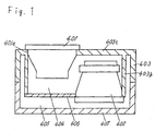
- Fig.1 is a cross sectional view showing a Kelton type speaker system having passive radiator, according to a first embodiment of the present invention.
- Fig.2 is an exploded perspective view of the speaker system of Fig.1.
- Fig.3 is an equivalent circuit diagram of the speaker system of Fig.1.
- Fig.4 is a block diagram of a sound producing apparatus comprising the speaker system of Fig.1 with a built-in power amplifier to be used as subwoofer.
- Fig.5 is a block diagram showing the sound feedback circuit of Fig.4.
- Fig.6 is a constitution of a car-borne sound apparatus comprising the subwoofer of Fig.4.
- Fig.7 illustrates vibration level; that of a conventional speaker box in (a), that of the speaker box of Fig.1 in (b).
- Fig.8 shows frequency characteristics of a sound produced by a conventional speaker system in (a), those by the speaker system of Fig.1 in (b).
- Fig.9 is a block diagram of a sound producing apparatus having the speaker system of Fig.1 used as subwoofer.
- Fig.10 is a cross sectional view showing a modification of the speaker system of Fig.1, where the passive radiator is divided.
- Fig.11 is a cross sectional view showing another modification of the speaker system of Fig.1, where a duct is used in place of the passive radiator.
- Fig.12 is a cross sectional view showing a still other modification of the speaker system of Fig.1, where a diffuser is attached on the passive radiator.
- Fig.13 is a cross sectional view of a Kelton type speaker system having passive radiator according to a second embodiment of the present invention.
- Fig.14 is a cross sectional view of a conventional Kelton type speaker system having passive radiator.
- Fig.15 is an equivalent circuit diagram of the conventional speaker system of Fig.14.
- Fig.16 compares various systems by frequency characteristics curves in the low frequency range.
- Speaker unit 402 is mounted on an opening of a cylinder 403b protruding from a top board 403a of baffle 403 at a place inner from the end.
- the remaining portion of opening of cylinder 403b is closed with a sub-baffle 406; the front closed cavity 404 is formed with top board 403a, cylinder 403b and sub-baffle 406.
- the baffle 403 is comprised of a high rigidity material, the top board 403a is made to have the highest rigidity.
- the manufacturing process may be simplified by gluing or welding a diaphragm 401a of passive radiator 401 direct to the top board 403a.
- Fig.3 shows an equivalent circuit diagram of the speaker system of Fig.1.
- the equivalent circuit comprises an electro-magnetic resistance 501 due to counter electromotive force of speaker unit etc., a mechanical resistance 502 of speaker unit, an equivalent mass 503 due to the mass of speaker diaphragm etc., a compliance 504 due to damper and edge etc. of speaker unit, a transformer 505 conducting a sound output of speaker unit to a passive radiator in a reverse phase in proportion to the ratio of areas, a mechanical resistance 506 of passive radiator, a compliance 507 due to damper and edge etc. of passive radiator, an equivalent mass 508 due to the mass of passive radiator diaphragm etc., a compliance 509 due to front closed cavity, and a compliance 510 due to back closed cavity.
- Fig.7(a), Fig.7(b) compare the vibration level of Kelton type speaker box having passive radiator; characteristics curve 1001 represents the vibration level of a conventional speaker box, 1002 represents the vibration level of a speaker box according to the present embodiment; measured in both cases at the surface of baffle.
- Fig.8(a), Fig.8(b) compare the frequency characteristics of Kelton type speaker box having passive radiator; curve 1101 represents the sound frequency characteristics of a conventional speaker box, curve 1102 represents the sound frequency characteristics of a speaker box according to the present embodiment.
- speaker unit 402 is mounted in a reverse orientation relative to passive radiator 401, and a sound output from the back of speaker unit 402 is conducted via the air of front closed cavity 404 to passive radiator 401 to produce a sound therefrom.
- the function of sub-baffle 406 is simply to split a space into front closed cavity 404 and back closed cavity 405.
- the source of vibration, namely speaker unit 402 and passive radiator 401 are mounted direct onto the baffle 403, the rigidity of which being the highest; therefore, the unwanted vibration of sub-baffle 406 due to counteraction of speaker unit 402 is significantly reduced, and the unwanted vibration of speaker system itself is reduced. From the comparison of the conventional vibration level 1001 and that of the present embodiment 1002, it is understood that the vibration of speaker box is substantially reduced in the present embodiment.
- the direct mounting of speaker unit 402 onto baffle 403 helps keep the volume ratio of the front closed cavity reduced. This brings about an improved limit of low range production in the present embodiment, as represented by the sound frequency characteristics 1102 versus conventional 1101; thus the sound characteristics of a speaker system is improved.
- the back closed cavity 405 is to seal the front sound output of speaker unit 402 in, so as the front sound output from speaker unit does not interfere with the sound output from passive radiator.
- a sound output from the back of speaker unit 402 is conducted via the air of front closed cavity 404 to passive radiator 401 to obtain a sound output from the passive radiator 401, therefore the speaker unit 402 and the passive radiator 401 are reverse-phased.
- Transformer 505 represents the above described situation.
- the sound signal input terminal of a speaker system according to the present embodiment is coupled with speaker unit 402 in the reverse phase.
- Fig.4 is a block diagram showing an application of the present embodiment, a sound producing apparatus in which the speaker system of Fig.1 with built-in power amplifier is used as subwoofer.
- the sound producing apparatus comprises a pulse width modulating type power amplifier 605 which amplifies only the low range signal of sound input signal, a speaker system of Fig.1 606 which reproduces sound output signal from power amplifier 605, and a sound feedback circuit 607 which detects with a microphone 602 a sound signal radiated from speaker system 606 for controlling the sound signal based on output signal from the microphone 602.
- the feedback circuit 607 is formed in a stage before the power amplifier 605.
- the sound feedback circuit 607 and power amplifier 605 constitute a power amplifying means for amplifying only the low range signal of sound output signal from a sound source 611, and delivers the amplified to the speaker system 606.
- the sound feedback circuit 607 comprises, as shown in Fig.5, a subtracter 601 in which an input terminal 1 to be connected with output of the sound source 611 is connected to a reverse input terminal, a microphone amplifier 603 to which an output signal of microphone 602 is inputted, and an adder/subtracter 604 which processes the output of microphone amplifier 603 and the sound signal to be inputted to power amplifier 605 arithmetically, the output of adder/subtracter 604 is connected to a non-reversal input terminal of the subtracter 601.
- the pulse width modulation type power amplifier 605 is a power amplifier which is compact yet yields a high output. By incorporating the power amplifier 605 in advance within a sound producing apparatus, integration with other sound producing apparatus for a higher performance turns out easy. The startup of sound producing output is also improved by a servo-effect of the sound feedback circuit 607.
- Fig.6 shows a constitution of a car-borne sound producing apparatus, in which a speaker system according to the present embodiment is incorporated as subwoofer. Basically, this is comprised of a sound source 611 and a full-range speaker system 612.
- the sound source 611 comprises a sound source equipment 611a such as a compact disk player, a compact cassette player, a tuner etc., an adjusting section 611b for adjusting the volume, tone of sound source, and a power amplifier 611c for amplifying sound output signal therefrom.
- the full-range speaker system 612 reproduces sound output signal of sound source 611 in a room of a car.
- the subwoofer 613 is a Kelton type speaker system having passive radiator according to the present embodiment, coupled with sound output signal from sound source 611.
- the use of subwoofer 613 improves the low range frequency characteristics.
- a phase relative to other sound producing apparatus may be optimized by delivering to subwoofer 613 a sound signal which is reverse-phased with respect to a sound signal applied to full-range speaker system 612.
- Fig.9 shows another car-borne sound producing apparatus in which a speaker system according to the present embodiment is used as subwoofer.
- the sound producing apparatus comprises a frequency voltage converter 701 which converts the frequency of car speed pulse delivered from car into a direct current voltage proportionate to the car speed, a voltage control amplifier 702 which amplifies sound input signal and outputs a sound signal proportionate to control voltage of the frequency voltage converter 701, an integration circuit 703 which prevents the output signal of voltage control amplifier 702 from making a frequent fluctuation according to control voltage of frequency voltage converter 701, a signal limiting circuit 704 which suppresses an excessive sound output signal when a sound volume of speaker system 606 is large enough not to be affected by room noise, a voltage control amplifier 705 which controls sound signal according to an output voltage when engine switch is ON so as an appropriate sound volume is obtained when a car is stopped with engine keep idling, a pulse width modulation type power amplifier 605 which amplifies only low range output power signal of voltage control amplifier 702, a speaker system according to the present embodiment 60
- the signal limiting circuit 704, feedback circuit 607 and power amplifier 605 constitute a power amplifying means for amplifying only the low range signal of sound output signal from voltage control amplifier 702, and delivering the amplified power to speaker system 606.
- the sound feedback circuit 607 is as shown in Fig.5.
- a sound signal delivered from sound source 611 is inputted to voltage control amplifier 705.
- the amplification of voltage control amplifier 705 goes higher for a certain level upon detecting a voltage that appears when engine switch of a car is ON.
- Frequency voltage converter 701 is supplied with pulse of a car speed, and delivers a control voltage proportionate to the car speed to voltage control amplifier 702 via integration circuit 703.
- a sound signal outputted from voltage control amplifier 705 is inputted to voltage control amplifier 702.
- the amplification of voltage control amplifier 702 is controlled in proportion to the control voltage of frequency voltage converter 701, namely a speed of the car.
- Sound output of voltage control amplifier 702 is inputted to signal limiting circuit 704.
- the signal limiting circuit 704 suppresses excessive sound volume accompanied by an increased car speed, when sound volume of subwoofer is large enough not to be affected by road noise and other room noises. Sound output signal of signal limiting circuit 704 is inputted to sound feedback circuit 607.
- the sound feedback circuit 607 detects the sound output of speaker system 606 with microphone 602, and forms a feedback loop with a microphone amplifier, a subtracter and an adder/subtracter, to improve the sound producing output of subwoofer through a servo-effect.
- Sound output of sound feedback circuit 607 is inputted to the pulse width modulation type power amplifier 605.
- the pulse width modulation type power amplifier 605 has a built-in low pass filter circuit etc., and amplifies only the low range power.
- Speaker system 606 is supplied with sound output signal of pulse width modulation type power amplifier 605, and outputs a reproduced sound in a room of the car.
- the noise level in a car room is higher when, in the order, a car is in stop, engine in idling state, running at low speed, running at moderate speed, running at high speed.
- the sound volume of speaker system, or subwoofer also increases in proportion to the level of room noise; therefore, the S/N ratio of a sound produced by the subwoofer is improved to keep staying in a fixed value, and a most appropriate sound is reproduced.
- the signal limiting circuit 704 suppresses unnecessary increase of subwoofer volume even if the running speed of a car is high. Even if running speed of a car changes frequently, the sound volume of subwoofer never shifts that frequent thanks to the work of integration circuit 703.
- the present sound producing apparatus installed in a car avoids the masking phenomenon, by shifting the amplification of power amplifier in low range signal according to a changing road noise caused by changing car speed as well as according to the existence or not of engine noise.
- Fig.10 shows a modification of the Kelton type speaker system of Fig.1 having passive radiator, employing a plurality of passive radiators 801, 802.
- the characteristics will be identical to those of the first embodiment. This provides additional freedom in designing a speaker system.
- Fig.11 shows another modification of the speaker system of Fig.1, in which a duct 902 is used in place of passive radiator 401 in Fig.1. If the area for internal diameter of duct 902 and the mass of air within duct 902 are identical to the diaphragm of passive radiator 401, a same characteristic as in the first embodiment will be obtainable. This helps simplify the structure of a speaker system.
- Fig.12 shows a speaker system which is the speaker system of Fig.1 further provided with a diffuser 408 on passive radiator 401.
- a sound output reproduced from passive radiator 401 is reflected by the diffuser 408 to be delivered through a sound output radiating section 409 placed in the side of speaker box and diffuser 408.
- This increases the effective equivalent mass against passive radiator 401, bringing about a further extended limit of low range reproduction.
- Fig.13 is a cross sectional view showing a Kelton type speaker system having passive radiator according to a second embodiment of the present invention.
- the speaker system comprises a passive radiator 1301 which actually produces a sound, a speaker unit 1302 for driving the passive radiator 1301 with a front sound output, a baffle 1303 on which the passive radiator 1301 and the speaker unit 1302 are mounted and constitutes a part of a speaker box, a front closed cavity 1304 for coupling a front sound output of speaker unit 1302 with passive radiator 1301, a back closed cavity 1305 for sealing the back sound output of speaker unit 1302 in, and a cabinet 1306 which constitutes a speaker box.
- the passive radiator 1301 is fixed direct to top board 1303a of baffle 1303, the speaker unit 1302 is mounted on the opening of a cylinder 1303b which is fixed to top board 1303a at a place inner from the end.
- a speaker system In a speaker system according to the second embodiment, sound output from the front of speaker unit 1302 is conducted via the air in front closed cavity 1304 to passive radiator 1301 to produce a sound therefrom.
- the source of vibration, namely speaker unit 1302 and passive radiator 1301 are mounted direct onto the baffle 1303, the rigidity of which being the highest; therefore, the unwanted vibration of speaker system due to counteraction of speaker unit 1302 is reduced.
- the direct mounting of speaker unit 1302 onto baffle 1303 helps keep the volume ratio of the front closed cavity reduced; which improves the sound characteristics of a speaker system.
- the back closed cavity 1305 is to seal the back sound output of speaker unit 1302 in, so as the back sound output from speaker unit 1302 does not interfere with the sound output of passive radiator 1301.
Landscapes
- Health & Medical Sciences (AREA)
- Otolaryngology (AREA)
- Physics & Mathematics (AREA)
- Engineering & Computer Science (AREA)
- Acoustics & Sound (AREA)
- Signal Processing (AREA)
- Obtaining Desirable Characteristics In Audible-Bandwidth Transducers (AREA)
- Details Of Audible-Bandwidth Transducers (AREA)
Applications Claiming Priority (3)
| Application Number | Priority Date | Filing Date | Title |
|---|---|---|---|
| JP08126096A JP3454005B2 (ja) | 1996-04-03 | 1996-04-03 | スピーカ装置および音響再生装置 |
| JP8126096 | 1996-04-03 | ||
| JP81260/96 | 1996-04-03 |
Publications (2)
| Publication Number | Publication Date |
|---|---|
| EP0800330A2 true EP0800330A2 (fr) | 1997-10-08 |
| EP0800330A3 EP0800330A3 (fr) | 2004-06-23 |
Family
ID=13741408
Family Applications (1)
| Application Number | Title | Priority Date | Filing Date |
|---|---|---|---|
| EP97105407A Ceased EP0800330A3 (fr) | 1996-04-03 | 1997-04-01 | Système de haut-parleur et dispositif générateur de son |
Country Status (3)
| Country | Link |
|---|---|
| US (1) | US6031919A (fr) |
| EP (1) | EP0800330A3 (fr) |
| JP (1) | JP3454005B2 (fr) |
Cited By (7)
| Publication number | Priority date | Publication date | Assignee | Title |
|---|---|---|---|---|
| GB2344016A (en) * | 1998-11-23 | 2000-05-24 | Ask Ind Spa | An ABR loudspeaker using body panels to form a closed air box within a motor vehicle |
| US7151836B1 (en) * | 1999-03-31 | 2006-12-19 | Matsushita Electric Industrial Co., Ltd. | Speaker apparatus and sound reproduction apparatus |
| EP1188353A4 (fr) * | 1999-03-02 | 2008-06-18 | American Tech Corp | Systeme de haut-parleur a bande passante |
| CN103079162A (zh) * | 2012-12-28 | 2013-05-01 | 宁波升亚电子有限公司 | 集成化扬声器,音箱及其制造方法 |
| WO2013097378A1 (fr) * | 2011-12-31 | 2013-07-04 | Huang Xinmin | Haut-parleur et procédé pour sa fabrication |
| WO2013097769A1 (fr) * | 2011-12-31 | 2013-07-04 | Huang Xinmin | Haut-parleur intégré, procédé pour sa fabrication et boîtier de haut-parleur |
| CN104902381A (zh) * | 2015-04-30 | 2015-09-09 | 常州英耐尔电子有限公司 | 一种四元车载强声拒止设备 |
Families Citing this family (22)
| Publication number | Priority date | Publication date | Assignee | Title |
|---|---|---|---|---|
| US6584204B1 (en) | 1997-12-11 | 2003-06-24 | The Regents Of The University Of California | Loudspeaker system with feedback control for improved bandwidth and distortion reduction |
| US6434240B1 (en) * | 1997-12-19 | 2002-08-13 | Charles J. Kulas | Sound isolation cabinet using two sound sources to generate complimentary sound waves |
| US7113607B1 (en) * | 1998-09-03 | 2006-09-26 | Mullins Joe H | Low frequency feedback controlled audio system |
| US6985593B2 (en) * | 2002-08-23 | 2006-01-10 | Bose Corporation | Baffle vibration reducing |
| US7551749B2 (en) * | 2002-08-23 | 2009-06-23 | Bose Corporation | Baffle vibration reducing |
| US20040125922A1 (en) * | 2002-09-12 | 2004-07-01 | Specht Jeffrey L. | Communications device with sound masking system |
| US6604602B1 (en) * | 2002-09-30 | 2003-08-12 | Chae Yong Kim | Separable speaker cover box containing speaker system |
| US7068806B2 (en) * | 2003-01-14 | 2006-06-27 | Walsh Casey P | Condensed speaker system |
| US20060120824A1 (en) * | 2004-11-19 | 2006-06-08 | Miehl Andrew P | Method and system for acoustic fastening |
| US7386137B2 (en) | 2004-12-15 | 2008-06-10 | Multi Service Corporation | Sound transducer for solid surfaces |
| US20060126885A1 (en) * | 2004-12-15 | 2006-06-15 | Christopher Combest | Sound transducer for solid surfaces |
| JP2010010727A (ja) * | 2008-06-24 | 2010-01-14 | Funai Electric Co Ltd | 小型スピーカ装置およびテレビジョン装置 |
| US8180076B2 (en) * | 2008-07-31 | 2012-05-15 | Bose Corporation | System and method for reducing baffle vibration |
| US20120288130A1 (en) * | 2011-05-11 | 2012-11-15 | Infineon Technologies Ag | Microphone Arrangement |
| DE102012025422B4 (de) * | 2012-10-23 | 2023-06-01 | Gerwin Barkam | Vorrichtung zur Resonanzminimierung von Gehäusen |
| CN105025421A (zh) * | 2014-04-17 | 2015-11-04 | 有限会社左尔佐 | 扬声器 |
| US9525932B2 (en) * | 2015-01-26 | 2016-12-20 | Bose Corporation | Acoustic device having active drivers mounted to a passive radiator diaphragm |
| JP6799323B2 (ja) * | 2017-04-04 | 2020-12-16 | 有限会社ゾルゾ | スピーカ |
| CN207869382U (zh) * | 2018-01-30 | 2018-09-14 | 瑞声科技(新加坡)有限公司 | 扬声器箱 |
| CN111726729A (zh) * | 2019-03-19 | 2020-09-29 | 清远市爱声音响科技有限公司 | 差动式指向低频音箱 |
| TWI734382B (zh) * | 2020-02-17 | 2021-07-21 | 大陸商東莞寶德電子有限公司 | 環狀輻射音箱結構 |
| CN114449382B (zh) | 2020-11-04 | 2024-09-20 | 捷普电子(新加坡)公司 | 扬声装置 |
Family Cites Families (11)
| Publication number | Priority date | Publication date | Assignee | Title |
|---|---|---|---|---|
| DE2446982C3 (de) * | 1974-10-02 | 1978-03-30 | Braun Ag, 6000 Frankfurt | Verfahren für den Betrieb von Lautsprecheranlagen und Vorrichtung zur Durchführung dieses Verfahrens |
| DE2659028C3 (de) * | 1976-12-27 | 1979-05-31 | Dasy Inter S.A., Genf (Schweiz) | Schaltungsanordnung zum Verhindern von Rückkopplungen |
| JPS6489700A (en) * | 1987-09-30 | 1989-04-04 | Hitachi Ltd | Speaker system |
| US4944018A (en) * | 1988-04-04 | 1990-07-24 | Bose Corporation | Speed controlled amplifying |
| US4875546A (en) * | 1988-06-02 | 1989-10-24 | Teledyne Industries, Inc. | Loudspeaker with acoustic band-pass filter |
| US4924963A (en) * | 1989-01-05 | 1990-05-15 | Polk Investment Corp. | Compact and efficient sub-woofer system and method for installation in structural partitions |
| US5092424A (en) * | 1990-12-03 | 1992-03-03 | Bose Corporation | Electroacoustical transducing with at least three cascaded subchambers |
| US5191618A (en) * | 1990-12-20 | 1993-03-02 | Hisey Bradner L | Rotary low-frequency sound reproducing apparatus and method |
| EP0548836B1 (fr) * | 1991-12-20 | 1997-06-11 | Matsushita Electric Industrial Co., Ltd. | Appareil haut-parleur par la reproduction des graves |
| US5475764A (en) * | 1992-09-30 | 1995-12-12 | Polk Investment Corporation | Bandpass woofer and method |
| US5471019A (en) * | 1994-12-29 | 1995-11-28 | Sounds Resources, Inc. | Multiple chamber loudspeaker system |
-
1996
- 1996-04-03 JP JP08126096A patent/JP3454005B2/ja not_active Expired - Fee Related
-
1997
- 1997-04-01 EP EP97105407A patent/EP0800330A3/fr not_active Ceased
- 1997-04-02 US US08/832,467 patent/US6031919A/en not_active Expired - Lifetime
Non-Patent Citations (2)
| Title |
|---|
| FINCHAM L.R.: "A BANDPASS LOUDSPEAKER ENCLOSURE", PREPRINTS OF PAPERS PRESENTED AT THE AES CONVENTION, vol. 63, no. 1512, May 1979 (1979-05-01), pages 1 - 16, XP008028211 * |
| GEDDES E.R.: "AN INTRODUCTION TO BAND-PASS LOUDSPEAKER SYSTEM", JOURNAL OF THE AUDIO ENGINEERING SOCIETY., vol. 5, 1989, AUDIO ENGINEERING SOCIETY, NEW YORK, NY., pages 308 - 342, XP008028207 * |
Cited By (10)
| Publication number | Priority date | Publication date | Assignee | Title |
|---|---|---|---|---|
| GB2344016A (en) * | 1998-11-23 | 2000-05-24 | Ask Ind Spa | An ABR loudspeaker using body panels to form a closed air box within a motor vehicle |
| GB2344016B (en) * | 1998-11-23 | 2003-02-26 | Ask Ind Spa | Passive elements in closed volume for loudspeakers |
| DE19956254C2 (de) * | 1998-11-23 | 2003-08-21 | Ask Ind Spa | Passives Element zum Betrieb zusammen mit einem aktiven Schallwandler eines Lautsprechers |
| EP1188353A4 (fr) * | 1999-03-02 | 2008-06-18 | American Tech Corp | Systeme de haut-parleur a bande passante |
| US7151836B1 (en) * | 1999-03-31 | 2006-12-19 | Matsushita Electric Industrial Co., Ltd. | Speaker apparatus and sound reproduction apparatus |
| WO2013097378A1 (fr) * | 2011-12-31 | 2013-07-04 | Huang Xinmin | Haut-parleur et procédé pour sa fabrication |
| WO2013097769A1 (fr) * | 2011-12-31 | 2013-07-04 | Huang Xinmin | Haut-parleur intégré, procédé pour sa fabrication et boîtier de haut-parleur |
| CN103079162A (zh) * | 2012-12-28 | 2013-05-01 | 宁波升亚电子有限公司 | 集成化扬声器,音箱及其制造方法 |
| CN103079162B (zh) * | 2012-12-28 | 2018-08-28 | 宁波升亚电子有限公司 | 集成化扬声器,音箱及其制造方法 |
| CN104902381A (zh) * | 2015-04-30 | 2015-09-09 | 常州英耐尔电子有限公司 | 一种四元车载强声拒止设备 |
Also Published As
| Publication number | Publication date |
|---|---|
| JPH09271092A (ja) | 1997-10-14 |
| JP3454005B2 (ja) | 2003-10-06 |
| US6031919A (en) | 2000-02-29 |
| EP0800330A3 (fr) | 2004-06-23 |
Similar Documents
| Publication | Publication Date | Title |
|---|---|---|
| US6031919A (en) | Loudspeaker system and sound reproducing apparatus | |
| JP5118205B2 (ja) | ドアに実装された構成要素を備えた車両オーディオシステム | |
| CN110267174B (zh) | 一种基于微型扬声器的车内独立声场系统 | |
| JP2009017485A (ja) | ヘッドホン | |
| US4493389A (en) | Speaker assembly | |
| JPH0628876Y2 (ja) | 低音域再生用スピーカシステム | |
| US4424416A (en) | Acoustic reproducing apparatus | |
| US5099948A (en) | Compact woofer speaker system | |
| JP2976284B2 (ja) | スピーカシステムの低音増強装置 | |
| JP3790528B2 (ja) | スピーカシステム | |
| JP2005294887A (ja) | 音響システム用パーツおよび音響システム | |
| CN111479192B (zh) | 一种双12寸有源四分频线性阵列音箱 | |
| JP3674089B2 (ja) | スピーカシステム | |
| JPH10336781A (ja) | 音響再生装置 | |
| JPH02195797A (ja) | スピーカシステム | |
| US20020012439A1 (en) | Diaphragm-type bass loudspeaker | |
| JP3230078B2 (ja) | スピーカシステムの低音増強装置 | |
| JPS59165600A (ja) | 自動車用音響装置 | |
| JPH0715782A (ja) | スピーカユニット | |
| JPH1079993A (ja) | シートオーディオ装置 | |
| KR102694789B1 (ko) | 드라이버 설치용 브라켓을 가지는 하이브리드 리시버 | |
| JP3475909B2 (ja) | 音響再生システム | |
| GB2037534A (en) | Loudspeakers | |
| JPH06205488A (ja) | スピーカーシステム | |
| JPH01887A (ja) | スピ−カシステム |
Legal Events
| Date | Code | Title | Description |
|---|---|---|---|
| PUAI | Public reference made under article 153(3) epc to a published international application that has entered the european phase |
Free format text: ORIGINAL CODE: 0009012 |
|
| AK | Designated contracting states |
Kind code of ref document: A2 Designated state(s): DE FR GB IT SE |
|
| PUAL | Search report despatched |
Free format text: ORIGINAL CODE: 0009013 |
|
| AK | Designated contracting states |
Kind code of ref document: A3 Designated state(s): DE FR GB IT SE |
|
| 17P | Request for examination filed |
Effective date: 20040707 |
|
| 17Q | First examination report despatched |
Effective date: 20070309 |
|
| RAP1 | Party data changed (applicant data changed or rights of an application transferred) |
Owner name: PANASONIC CORPORATION |
|
| STAA | Information on the status of an ep patent application or granted ep patent |
Free format text: STATUS: THE APPLICATION HAS BEEN REFUSED |
|
| 18R | Application refused |
Effective date: 20081008 |