EP0800876A2 - Machine de dressage - Google Patents
Machine de dressage Download PDFInfo
- Publication number
- EP0800876A2 EP0800876A2 EP97105817A EP97105817A EP0800876A2 EP 0800876 A2 EP0800876 A2 EP 0800876A2 EP 97105817 A EP97105817 A EP 97105817A EP 97105817 A EP97105817 A EP 97105817A EP 0800876 A2 EP0800876 A2 EP 0800876A2
- Authority
- EP
- European Patent Office
- Prior art keywords
- straightening
- units
- machine according
- adjusting
- straightening machine
- Prior art date
- Legal status (The legal status is an assumption and is not a legal conclusion. Google has not performed a legal analysis and makes no representation as to the accuracy of the status listed.)
- Granted
Links
Images

Classifications
-
- B—PERFORMING OPERATIONS; TRANSPORTING
- B21—MECHANICAL METAL-WORKING WITHOUT ESSENTIALLY REMOVING MATERIAL; PUNCHING METAL
- B21F—WORKING OR PROCESSING OF METAL WIRE
- B21F1/00—Bending wire other than coiling; Straightening wire
- B21F1/02—Straightening
Definitions
- the invention relates to a straightening machine for aligning wire with a straightening set which comprises a plurality of straightening units which can be adjusted in their radial position relative to the longitudinal axis of the straightening set.
- a straightening machine with adjustable straightening units is known from EP-A1-620-058.
- the straightening set is formed by a rotor which can be rotated about its longitudinal axis by a rotary drive and which, as straightening units, comprises straightening nozzles through which the wire to be aligned is guided.
- the directional nozzles are mounted so as to be radially displaceable and their position can be adjusted jointly via a displacement element which has inclined planes which act laterally on the holders of the directional nozzles.
- the disadvantage of this device is that the rotor has a relatively high weight and thus a high moment of inertia when accelerating or braking, that the adjustment is relatively coarse and that an adjustment to the properties of the wire (for example its internal stresses depending on the type of manufacture) only is possible to a limited extent.
- the straightening nozzles are individually manually adjusted, which of course involves a lot of work. It is therefore common to provide several rotors set to different wire diameters, which can be replaced if necessary.
- a straightening machine is known from EP-A1-619 154, in which the straightening set is formed by a plurality of straightening rollers, of which every second straightening roller can be adjusted in its radial position via an adjusting knob. With this straightening machine, too, the changeover to a different wire diameter is labor-intensive.
- the object of the invention is to provide a novel straightening machine, by means of which the disadvantages of the previously known straightening machines are overcome and which can be quickly and precisely reproducibly adjusted to different wire diameters.
- this is achieved in a straightening machine of the type mentioned at the outset by the fact that the radial positions of individual straightening units of the straightening set can be adjusted remotely via the adjusting device, the adjusting device having at least one adjusting unit which is decoupled from a first passive position in which it is decoupled from the straightening units , can be transferred into a second active position in which it is in engagement with at least one straightening unit for adjusting the same.
- the invention can be used in straightening machines with a roller straightening set, in which the straightening units are formed by rollers between which the wire is guided.
- straightening nozzles through which the wire is guided are provided as straightening units. Because the actuating units are decoupled from the straightening units during operation of the straightening machines, the rotating mass can be kept low.
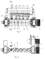
- the straightening machine shown in FIGS. 1 to 3 has a rotor 2 which is rotatably mounted about the axis 1 and which contains the straightening units 3.
- the rotor 2 is driven by a motor 6 via V-belts 4 and associated V-shafts 5.
- the wire to be aligned is drawn off from a coil and along the rotor of the straightening machine guided. As a result, the aligned wire can be cut to a straight round steel rod.
- the straightening set 7 comprises five straightening units 3 designed as straightening nozzles 8, which are fixed in the rotor 2 with respect to their axial position and radially, i.e. can be individually adjusted by an adjusting device 10 perpendicular to the longitudinal axis 1 of the straightening set 7.
- the directional nozzle 8 has a nozzle plate 9 which contains the actual nozzle 11.
- the nozzle plate 9 is slidably mounted in the nozzle frame 12 via guide strips 12a which engage in guide grooves of the nozzle plate 9.
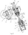
- the radial adjustment of the straightening nozzle 8 takes place via a spindle drive 13. This is formed by a hollow thread 9a contained in the nozzle plate 9 and an adjusting screw 14 mounted in the nozzle frame 12.
- a latching device 15 (see FIG. 2) is provided, which has a latching ring 16 rigidly connected to the adjusting screw 14 and provided with radial bores and spring balls which are mounted in a bolt 17 and are under spring force includes, which can snap into the holes in the locking ring.
- the locking device achieves a defined angular position of the adjusting screw 14.
- a sealing sleeve 18 pinned to the adjusting screw 14 is provided in order to prevent the ingress of dirt.
- the actuating device 10 comprises a plurality of actuating units 20 assigned to the straightening units 3, one actuating unit 20 being provided for each straightening unit 3.
- the actuating units 20 are driven together via a chain 21, which is driven by an actuator motor 23 via a chain wheel 22.
- the adjusting units 20 have adjusting shafts 24, the adjusting nuts 25 of which can be brought into engagement with the adjusting screws 14.
- clamping couplings are provided which comprise wedge sleeves 27 driven by the chain 21 via chain wheels 26, in which the adjusting shafts 24, are designed as spline shafts are stored.
- the adjusting shafts 24 are therefore mounted in the wedge sleeves 27 in a rotationally fixed manner but axially displaceable by pneumatic piston-cylinder units 28 and can move from the piston-cylinder units 28 from a first passive position into a second active position in which they are engaged with the respective adjusting screw. be transferred.
- the setting of the actuating units is carried out by first bringing the rotor into the setting position in which the displacement axis 29 of the respective directional nozzle 8 coincides with the axis 30 of the actuating unit 20.
- one of the adjusting shafts 24 is lowered into the active position by means of the piston-cylinder unit 28 until the adjusting nut 25 is seated on the adjusting screw 14.
- the adjusting screw is now rotated by the desired angular range via the actuator motor 23.
- a rotary encoder 31 can be provided for monitoring and recording the rotary movement of the adjusting screw 14.
- a stepping motor can also be provided as the actuator motor 23, which can be rotated by a defined angular amount, so that in this case no rotary encoder is necessary. In this way, a defined position of the nozzle 11 can be approached and stored in an electronic memory of a control device.
- the actuating shaft 24 is then retracted. The process can then be repeated for all straightening nozzles 8.
- the setting process can be controlled by a user via a control panel.
- a control device which automatically and automatically executes the entire setting process based on previously stored setting values.
- An important advantage of the straightening machine according to the invention is that the rotating masses of the adjustable rotor are only slightly higher than in conventional rotors that cannot be adjusted remotely.
- the rotor can also have straightening rollers instead of straightening nozzles over which the wire is guided.
- the surface of such a straightening roller generally has a concave, approximately parabolic profile.
- the straightening rollers can in turn be adjusted in their radial positions via spindle drives and an adjusting device is provided for individually adjusting the radial positions of the straightening rollers, which corresponds to that described above.
- the idea according to the invention of providing an adjusting device for the remote-controlled or controlled adjustment of the radial bearings of the straightening units is not restricted to straightening machines with a rotor straightening set, but can also be used for straightening machines with a fixed roller straightening set, as shown in FIG. 4.
- the actuating units 20 of the actuating device 10 are only individually assigned to the upper six rollers 40 here.
- the lower five rollers 40 could also be individually adjustable.
- the actuating device 10 in turn functions in exactly the same way as described above and a spindle drive can again be provided for the radial adjustment of the rollers 40.
- two of the straightening sets shown in FIG. 4 are preferably used, which are perpendicular to one another and through which the wire passes in succession.
Landscapes
- Engineering & Computer Science (AREA)
- Mechanical Engineering (AREA)
- Wire Processing (AREA)
- Soil Working Implements (AREA)
- Vehicle Body Suspensions (AREA)
- Formation And Processing Of Food Products (AREA)
- Shaping Of Tube Ends By Bending Or Straightening (AREA)
Applications Claiming Priority (3)
| Application Number | Priority Date | Filing Date | Title |
|---|---|---|---|
| AT67296 | 1996-04-12 | ||
| AT0067296A AT408421B (de) | 1996-04-12 | 1996-04-12 | Richtmaschine |
| AT672/96 | 1996-04-12 |
Publications (3)
| Publication Number | Publication Date |
|---|---|
| EP0800876A2 true EP0800876A2 (fr) | 1997-10-15 |
| EP0800876A3 EP0800876A3 (fr) | 1998-05-20 |
| EP0800876B1 EP0800876B1 (fr) | 2000-01-12 |
Family
ID=3496787
Family Applications (1)
| Application Number | Title | Priority Date | Filing Date |
|---|---|---|---|
| EP97105817A Expired - Lifetime EP0800876B1 (fr) | 1996-04-12 | 1997-04-09 | Machine de dressage |
Country Status (3)
| Country | Link |
|---|---|
| EP (1) | EP0800876B1 (fr) |
| AT (2) | AT408421B (fr) |
| DE (1) | DE59700991D1 (fr) |
Cited By (6)
| Publication number | Priority date | Publication date | Assignee | Title |
|---|---|---|---|---|
| EP0967030A3 (fr) * | 1998-06-26 | 2001-04-04 | WITELS APPARATE-MASCHINEN ALBERT GmbH & Co. KG | Procédé et dispositif de réglage des rouleaux d'un dispositif de redressage |
| ITBO20080633A1 (it) * | 2008-10-15 | 2010-04-16 | Schnell Spa | Apparecchiatura per raddrizzare profilati metallici e simili |
| CN106001321A (zh) * | 2015-03-30 | 2016-10-12 | 矢崎总业株式会社 | 线材矫正装置 |
| CN109175149A (zh) * | 2018-08-09 | 2019-01-11 | 广东新宝精密制造股份有限公司 | 一种钢丝矫直装置 |
| CN113184626A (zh) * | 2021-05-07 | 2021-07-30 | 江苏艾可森钢绳有限公司 | 一种有矫直刮油功能的改性高密度聚乙烯涂塑钢丝绳绕线装置 |
| CN113828706A (zh) * | 2021-09-06 | 2021-12-24 | 上海威克鲍尔通信科技有限公司 | 适用于多种导线切换、校直、出线的一体装置 |
Families Citing this family (2)
| Publication number | Priority date | Publication date | Assignee | Title |
|---|---|---|---|---|
| CN101979177B (zh) * | 2010-11-17 | 2012-05-30 | 建科机械(天津)股份有限公司 | 数控钢筋笼成型机的箍筋矫直可调装置 |
| DE102010054111B4 (de) | 2010-12-10 | 2013-06-13 | Wafios Ag | Richtwerk zum rotierenden Richten von Draht |
Family Cites Families (5)
| Publication number | Priority date | Publication date | Assignee | Title |
|---|---|---|---|---|
| US3857266A (en) * | 1973-08-24 | 1974-12-31 | Handy & Harman Specialty Metal | Rotary arbor wire straightener |
| NL7604956A (nl) * | 1975-05-30 | 1976-12-02 | Louis Hans | Machine voor het richten van draden. |
| JPS63203215A (ja) * | 1987-02-18 | 1988-08-23 | Kawazoe Kikai Seisakusho:Kk | 2ロ−ル式丸棒矯正機における遠隔式ロ−ル角度調整装置 |
| ES2023101A4 (es) * | 1987-04-14 | 1992-01-01 | Panayotis Anagnostopoulos | Maquina para el procesado de alambre. |
| DE4311566A1 (de) * | 1993-04-08 | 1994-10-13 | Peddinghaus Rolf | Richtmaschine für Draht |
-
1996
- 1996-04-12 AT AT0067296A patent/AT408421B/de not_active IP Right Cessation
-
1997
- 1997-04-09 DE DE59700991T patent/DE59700991D1/de not_active Expired - Lifetime
- 1997-04-09 AT AT97105817T patent/ATE188634T1/de active
- 1997-04-09 EP EP97105817A patent/EP0800876B1/fr not_active Expired - Lifetime
Cited By (7)
| Publication number | Priority date | Publication date | Assignee | Title |
|---|---|---|---|---|
| EP0967030A3 (fr) * | 1998-06-26 | 2001-04-04 | WITELS APPARATE-MASCHINEN ALBERT GmbH & Co. KG | Procédé et dispositif de réglage des rouleaux d'un dispositif de redressage |
| ITBO20080633A1 (it) * | 2008-10-15 | 2010-04-16 | Schnell Spa | Apparecchiatura per raddrizzare profilati metallici e simili |
| WO2010044009A1 (fr) * | 2008-10-15 | 2010-04-22 | Schnell S.P.A. | Appareil de redressage de profils métalliques et analogues, et procédé de réglage d’éléments de redressage dans un tel appareil |
| CN106001321A (zh) * | 2015-03-30 | 2016-10-12 | 矢崎总业株式会社 | 线材矫正装置 |
| CN109175149A (zh) * | 2018-08-09 | 2019-01-11 | 广东新宝精密制造股份有限公司 | 一种钢丝矫直装置 |
| CN113184626A (zh) * | 2021-05-07 | 2021-07-30 | 江苏艾可森钢绳有限公司 | 一种有矫直刮油功能的改性高密度聚乙烯涂塑钢丝绳绕线装置 |
| CN113828706A (zh) * | 2021-09-06 | 2021-12-24 | 上海威克鲍尔通信科技有限公司 | 适用于多种导线切换、校直、出线的一体装置 |
Also Published As
| Publication number | Publication date |
|---|---|
| AT408421B (de) | 2001-11-26 |
| EP0800876B1 (fr) | 2000-01-12 |
| ATA67296A (de) | 2001-04-15 |
| DE59700991D1 (de) | 2000-02-17 |
| ATE188634T1 (de) | 2000-01-15 |
| EP0800876A3 (fr) | 1998-05-20 |
Similar Documents
| Publication | Publication Date | Title |
|---|---|---|
| DE4323009C2 (de) | Vorrichtung zum Erzeugen der Steigung einer Feder in einer Federwindeinrichtung | |
| DE3828181A1 (de) | Messvorrichtung, insbesondere zur messung der durchmesser von walzen bei walzenschleifmaschinen | |
| EP0620058B1 (fr) | Machine à dressage pour fils | |
| DE3609290A1 (de) | Schraegwalzwerk | |
| EP0800876B1 (fr) | Machine de dressage | |
| DE3915784C1 (fr) | ||
| DE3447595C2 (fr) | ||
| DE3603561C1 (de) | Einrichtung zum automatischen Verstellen einer Stangenfuehrung an einer numerisch gesteuerten Drehmaschine | |
| DE3235820A1 (de) | Vorrichtung zur befestigung eines zubehoerteils am werkstueckspindelstock einer werkzeugmaschine | |
| DE2803645C2 (de) | Kurbelwellenfräsmaschine | |
| CH663923A5 (de) | Abrichteinrichtung fuer bahngesteuertes abrichten von schleifscheibenprofilen. | |
| DE2801107C3 (de) | Verfahren und Vorrichtung zur Herstellung von zylindrischen Schraubenfedern aus Draht | |
| DE3844343C2 (de) | Kraftbetätigtes Backenspannfutter für exzentrisch zu spannende Werkstücke, insbesondere Kurbelwellen | |
| DE3936200C1 (fr) | ||
| DE2108338B2 (de) | Schneidvorrichtung zum Unterteilen kontinuierlich angelieferter Material-Stränge | |
| CH664921A5 (de) | Einrichtung zum abrichten von doppelkegelschleifkoerpern. | |
| WO1990015692A1 (fr) | Broche entrainee en rotation | |
| DE2630224A1 (de) | Verfahren zum montieren von streckwerken auf einer streckwerksbank | |
| DE3738074C2 (fr) | ||
| DE3524438A1 (de) | Einrichtung zur zylinderfehlerkompensation an einer schleifmaschine | |
| DE2740616C3 (de) | Umformpresse, insbesondere Mehrstufenpresse | |
| DE10303215B4 (de) | Verfahren und Honmaschine zum Innenhonen von Werkstücken | |
| DE868686C (de) | Vorschubeinrichtung fuer die Werkzeuge auf Revolverkoepfen selbsttaetiger Drehbaenke | |
| EP1150785B1 (fr) | Appareil de laminage et procede de reglage dudit appareil | |
| EP0204878B1 (fr) | Laminoir en croix |
Legal Events
| Date | Code | Title | Description |
|---|---|---|---|
| PUAI | Public reference made under article 153(3) epc to a published international application that has entered the european phase |
Free format text: ORIGINAL CODE: 0009012 |
|
| AK | Designated contracting states |
Kind code of ref document: A2 Designated state(s): AT BE CH DE DK ES FI FR GR IT LI LU NL PT SE |
|
| PUAL | Search report despatched |
Free format text: ORIGINAL CODE: 0009013 |
|
| AK | Designated contracting states |
Kind code of ref document: A3 Designated state(s): AT BE CH DE DK ES FI FR GR IT LI LU NL PT SE |
|
| 17P | Request for examination filed |
Effective date: 19980609 |
|
| 17Q | First examination report despatched |
Effective date: 19980724 |
|
| GRAG | Despatch of communication of intention to grant |
Free format text: ORIGINAL CODE: EPIDOS AGRA |
|
| GRAG | Despatch of communication of intention to grant |
Free format text: ORIGINAL CODE: EPIDOS AGRA |
|
| GRAH | Despatch of communication of intention to grant a patent |
Free format text: ORIGINAL CODE: EPIDOS IGRA |
|
| GRAH | Despatch of communication of intention to grant a patent |
Free format text: ORIGINAL CODE: EPIDOS IGRA |
|
| GRAA | (expected) grant |
Free format text: ORIGINAL CODE: 0009210 |
|
| AK | Designated contracting states |
Kind code of ref document: B1 Designated state(s): AT BE CH DE DK ES FI FR GR IT LI LU NL PT SE |
|
| PG25 | Lapsed in a contracting state [announced via postgrant information from national office to epo] |
Ref country code: SE Free format text: THE PATENT HAS BEEN ANNULLED BY A DECISION OF A NATIONAL AUTHORITY Effective date: 20000112 Ref country code: GR Free format text: LAPSE BECAUSE OF NON-PAYMENT OF DUE FEES Effective date: 20000112 Ref country code: FI Free format text: LAPSE BECAUSE OF FAILURE TO SUBMIT A TRANSLATION OF THE DESCRIPTION OR TO PAY THE FEE WITHIN THE PRESCRIBED TIME-LIMIT Effective date: 20000112 Ref country code: ES Free format text: THE PATENT HAS BEEN ANNULLED BY A DECISION OF A NATIONAL AUTHORITY Effective date: 20000112 |
|
| REF | Corresponds to: |
Ref document number: 188634 Country of ref document: AT Date of ref document: 20000115 Kind code of ref document: T |
|
| ITF | It: translation for a ep patent filed | ||
| REG | Reference to a national code |
Ref country code: CH Ref legal event code: NV Representative=s name: ISLER & PEDRAZZINI AG Ref country code: CH Ref legal event code: EP |
|
| REF | Corresponds to: |
Ref document number: 59700991 Country of ref document: DE Date of ref document: 20000217 |
|
| PG25 | Lapsed in a contracting state [announced via postgrant information from national office to epo] |
Ref country code: LU Free format text: LAPSE BECAUSE OF NON-PAYMENT OF DUE FEES Effective date: 20000409 |
|
| PG25 | Lapsed in a contracting state [announced via postgrant information from national office to epo] |
Ref country code: PT Free format text: LAPSE BECAUSE OF FAILURE TO SUBMIT A TRANSLATION OF THE DESCRIPTION OR TO PAY THE FEE WITHIN THE PRESCRIBED TIME-LIMIT Effective date: 20000412 Ref country code: DK Free format text: LAPSE BECAUSE OF FAILURE TO SUBMIT A TRANSLATION OF THE DESCRIPTION OR TO PAY THE FEE WITHIN THE PRESCRIBED TIME-LIMIT Effective date: 20000412 |
|
| ET | Fr: translation filed | ||
| PLBE | No opposition filed within time limit |
Free format text: ORIGINAL CODE: 0009261 |
|
| STAA | Information on the status of an ep patent application or granted ep patent |
Free format text: STATUS: NO OPPOSITION FILED WITHIN TIME LIMIT |
|
| 26N | No opposition filed | ||
| REG | Reference to a national code |
Ref country code: CH Ref legal event code: PUE Owner name: PROGRESS HOLDING AG TRANSFER- PROGRESS MASCHINEN & Ref country code: CH Ref legal event code: PFA Free format text: PROGRESS AG TRANSFER- PROGRESS HOLDING AG |
|
| BECH | Be: change of holder |
Free format text: 20011002 *PROGRESS MASCHINEN & AUTOMATIONEN A.G. |
|
| REG | Reference to a national code |
Ref country code: FR Ref legal event code: TP Ref country code: FR Ref legal event code: CD |
|
| NLS | Nl: assignments of ep-patents |
Owner name: PROGRESS MASCHINEN & AUTOMATION AG |
|
| NLT1 | Nl: modifications of names registered in virtue of documents presented to the patent office pursuant to art. 16 a, paragraph 1 |
Owner name: PROGRESS HOLDING AG |
|
| REG | Reference to a national code |
Ref country code: CH Ref legal event code: PCAR Free format text: ISLER & PEDRAZZINI AG;POSTFACH 1772;8027 ZUERICH (CH) |
|
| REG | Reference to a national code |
Ref country code: FR Ref legal event code: PLFP Year of fee payment: 20 |
|
| PGFP | Annual fee paid to national office [announced via postgrant information from national office to epo] |
Ref country code: NL Payment date: 20160415 Year of fee payment: 20 |
|
| PGFP | Annual fee paid to national office [announced via postgrant information from national office to epo] |
Ref country code: DE Payment date: 20160429 Year of fee payment: 20 Ref country code: CH Payment date: 20160425 Year of fee payment: 20 |
|
| PGFP | Annual fee paid to national office [announced via postgrant information from national office to epo] |
Ref country code: AT Payment date: 20160429 Year of fee payment: 20 Ref country code: BE Payment date: 20160413 Year of fee payment: 20 Ref country code: FR Payment date: 20160405 Year of fee payment: 20 Ref country code: IT Payment date: 20160420 Year of fee payment: 20 |
|
| REG | Reference to a national code |
Ref country code: DE Ref legal event code: R071 Ref document number: 59700991 Country of ref document: DE |
|
| REG | Reference to a national code |
Ref country code: CH Ref legal event code: PL |
|
| REG | Reference to a national code |
Ref country code: NL Ref legal event code: MK Effective date: 20170408 |
|
| REG | Reference to a national code |
Ref country code: AT Ref legal event code: MK07 Ref document number: 188634 Country of ref document: AT Kind code of ref document: T Effective date: 20170409 |