EP0800885A2 - Dispositif pour le poinçonnage de dents de scie dans un matériau sous forme de bande - Google Patents
Dispositif pour le poinçonnage de dents de scie dans un matériau sous forme de bande Download PDFInfo
- Publication number
- EP0800885A2 EP0800885A2 EP97105649A EP97105649A EP0800885A2 EP 0800885 A2 EP0800885 A2 EP 0800885A2 EP 97105649 A EP97105649 A EP 97105649A EP 97105649 A EP97105649 A EP 97105649A EP 0800885 A2 EP0800885 A2 EP 0800885A2
- Authority
- EP
- European Patent Office
- Prior art keywords
- belt
- band
- conveyor
- belt conveyor
- advance
- Prior art date
- Legal status (The legal status is an assumption and is not a legal conclusion. Google has not performed a legal analysis and makes no representation as to the accuracy of the status listed.)
- Granted
Links
Images

Classifications
-
- B—PERFORMING OPERATIONS; TRANSPORTING
- B23—MACHINE TOOLS; METAL-WORKING NOT OTHERWISE PROVIDED FOR
- B23D—PLANING; SLOTTING; SHEARING; BROACHING; SAWING; FILING; SCRAPING; LIKE OPERATIONS FOR WORKING METAL BY REMOVING MATERIAL, NOT OTHERWISE PROVIDED FOR
- B23D65/00—Making tools for sawing machines or sawing devices for use in cutting any kind of material
- B23D65/02—Making saw teeth by punching, cutting, or planing
Definitions
- the present invention relates to a device for punching out saw teeth from a band material, which is conveyed discontinuously in advance steps of a predetermined length by means of a belt conveyor device and provided with the saw teeth along the longitudinal edge under a punch die which is clocked during the rest periods of advance.
- Such a device is generally known.
- the belt material is conveyed discontinuously in advance steps of a predetermined length by means of a belt conveyor device.
- the length of the advance steps is determined by the saw tooth pitch.
- Each sawtooth must be punched out individually in order to obtain the desired sharpness of the tooth tip. Therefore, a measure of the production speed of such band saws is the machine-related number of strokes with which the punching tool is driven in an oscillating manner.
- the punching tool is moved in an oscillating manner transversely to the direction of movement of the strip material in such a manner that the punching die punches a tooth out of the longitudinal edge of the supplied strip material during the idle driving times of the strip conveyor device.
- a belt path measuring device is provided for measuring the actually driven length of drive and that a control device for controlling a motor of the belt conveyor device is acted upon with the measurement signal, the control being carried out until the actually traveled length of tunneling with the predetermined length of the Advance step coincides.
- the advantage of the invention is that, regardless of any slippage that may occur during the advance of the strip material, an identical advance length is always traveled, so that the tooth pitch is identical over the entire length of the strip material.
- This advantage is achieved in that a control circuit is built between the discontinuously driven belt conveyor and the belt travel measuring device, which Controls the motor of the belt conveyor until the drive length actually covered corresponds to the specified length of the drive step.
- a target / actual comparison is therefore always carried out between the specified value for the tooth pitch and the actual length of the advance during a advance step.
- the driven length of the drive is detected without slippage and is fed to a control device for controlling the belt conveyor motor.
- the belt conveyor motor is driven until the actual value coincides with the target value by means of a constant target-actual comparison of the length traveled in each case with the predetermined value of the tooth pitch.
- the respective advance step is therefore brought up to the length of the tooth pitch. At that moment the belt conveyor motor is stopped.
- the invention has the further advantage that, owing to the slip-compensated step length of the advance, considerably higher stroke rates of the punch die can also be driven. As a result of the elimination of mechanical coupling between the drive cycles for propulsion and the stroke cycles for the punching process, any mechanical play is also eliminated, since the corresponding transmission links are also no longer necessary.
- measuring rollers or the like be provided. These measuring rollers are expediently mounted with low-friction bearings in order to enable a 1: 1 scanning of the differentially small drive path section present in each case.
- the path measuring roller must lie on the strip material that is being pulled past without slippage. Since the distance measuring roller can roll off practically without resistance, this requirement can be met.
- the belt conveyor motor is a discontinuously controlled servomotor.
- the control device comprises an assigned servo amplifier.
- Such a servo motor can be controlled extremely quickly and yet precisely in predetermined angular steps. Therefore, even small engine outputs enable a high number of strokes.
- a wear-free coupling between the belt conveyor motor and the actual belt drive can be achieved if a set of conveyor roller pairs is provided as the belt drive.
- One pair of conveyor rollers is arranged on the input side and the second pair of conveyor rollers is arranged on the output side of the punch die.
- the gear coupling between the belt conveyor motor and the conveyor roller pairs is formed by drives that are as slip-free as possible. Toothed belts are particularly suitable for this.
- a single conveyor motor can easily drive both pairs of conveyor rollers.
- band saw blades that can be produced with the device according to this invention are characterized in particular by saw teeth that lie on a single continuous straight line.
- the invention differs from the prior art. So far, the tape material has been guided in the tooth tip area at a stop. So that the tooth tips, which are now on a continuous straight line, are not unnecessarily impaired by contact with the stop, so that the stop does not wear out unnecessarily, so that the strip material is gently applied, only the strip back should now be guided over a corresponding strip back stop.
- the band back stop can be mounted so as to be displaceably movable transversely to the direction of belt conveying. In this way, the distance between the punching die and the band back is set as required by the geometry of the finished saw blade.
- the practically wear-free toothed slide guide that can be achieved with this is maintenance-free and remains dimensionally accurate even in uninterrupted production.
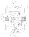
- the figures show a punching machine 1 for punching out saw teeth from a strip material 2.
- the strip material 2 is drawn off from a supply reel 3 and fed to a take-up reel 4.
- Unwinding reel 3 and reel spool 4 are connected to an unwinding drive 5 and rewinding drive 6, respectively.
- the unwinding drive 5 is controlled in such a way that, in front of the area of the punching machine 1 designated II-II, a leading swapping zone 7 in the strip material and a trailing swapping zone 8 in the strip material arise. These creasing zones are necessary to obtain precisely defined longitudinal tensions in the strip material 2 within the area designated II-II.
- the band material 2 is conveyed discontinuously by a band conveyor device 9 in the advance steps of a predetermined length and provided with saw teeth along the longitudinal edge under a punch die 14 clocked in advance during the rest periods of advance.
- a pair of input rollers 10 on the input side is provided within the area designated II-II, which cooperates with a pair of output rollers 11 on the output side.
- a common belt conveyor motor 22 is used for the drive, which is coupled to the input and output side conveyor roller pair 10, 11 via a traction mechanism drive 12 and 13, respectively.
- a tape path measuring device 15 is provided in the feed area of the tape before entering the area designated II-II.
- This tape path measuring device 15 consists of a measuring wheel 16 which rests on a broad side 17 of the tape material 2.
- a rotating pressure roller 19 is provided, which holds the strip material guided in between to the measuring wheel 16 with such a high driving force that the measuring wheel can tap the actually driven length without slippage when the strip material is propelled.
- the drive length actually traveled is fed to a control device 21 via the measurement signal line 20 and processed there as a signal.
- An output of the control device 21 is connected to the belt conveyor motor 22.
- the belt conveyor motor is controlled discontinuously via the control device 21 so that the belt path covered per drive step is identical in size with the predetermined length of the tooth pitch.
- control device 21 will carry out a constant comparison with a desired value corresponding to the tooth pitch 45 over the length of the actual path scanned by the measuring wheel 16 and actuate the belt conveyor motor 22 until the scanned path coincides with the tooth pitch 45.
- the control is therefore carried out until the drive length actually covered within the predetermined tooth pitch corresponds to the predetermined length of the advance step, the drive step corresponding to the dimension of the tooth pitch.
- the control device 21 also includes a servo amplifier 23 for the belt conveyor motor 22, which is designed here as a discontinuously controlled servo motor.
- a servo amplifier 23 for the belt conveyor motor 22 which is designed here as a discontinuously controlled servo motor.
- the fast and precise controllability of such servomotors can be implemented in the sense of the invention if the belt conveyor device 9 consists of a pair of input rollers 10 on the input side and a pair of output rollers 11 on the output side, and a slip-free traction drive via a toothed belt 12 or 13 from the belt conveyor motor 22 to the assigned pair of conveyor rollers 10 or 11 is excited.
- One conveyor roller is therefore always driven by the conveyor roller pairs, while the opposite conveyor roller serves to clamp the belt located between them.
- the predetermined clamping force between the clamping roller and the driven conveyor roller is so great that, taking into account the normal operating conditions, practically slip-free propulsion is ensured.
- the belt path measuring device 15 which rests on the belt material 2 to be conveyed via the rotatable measuring wheel 16, serves to determine this.
- the measuring wheel 15 is equally held by the opposing pressure roller 19 with a given pressing force against the strip material 2 running therebetween, so that the smooth-running measuring wheel can scan the actual propulsion without any slip.
- the toothed slide 24 is mounted in roller bearing guides 26 relative to the machine housing 25.
- the roller bearing guides can possibly be formed by needle bearings. This makes the toothed slide 24 light and Movable with low friction within the machine housing 25 and can therefore carry out high stroke rates without wear.
- the tooth punch 27 is moved from the top to the band material 2
- the counterplate 28 to the punching die 14 is located on the opposite bottom side, on which the band material 2 is laid flat during the punching process.
- a toothed slide eccentric 29 is provided, on which a connecting rod engages on a predetermined crank radius, which is in turn coupled to the straight toothed slide 24.
- the toothed slide 24 can therefore perform an oscillating lifting movement.
- This stroke movement is impressed on the toothed slide eccentric 29 by the punch motor 30.
- This stroke movement must be timed with the discontinuous advancing steps of the belt conveyor 9.
- an encoder 31 which is attached to the toothed slide eccentric 29 and cooperates with a stationary slave 32. The slave sends a corresponding signal to the control device 21 when the transmitter 31 and slave 32 are in the corresponding position. This signal causes the punch motor 30 to be released in the sense of a single punch stroke, the toothed slide eccentric 29 once completely rotating about its axis.
- the control device 21 is informed of the completion via the renewed signal from the receiver 32.
- the strip material 2 running past is scanned by the measuring wheel 16.
- a corresponding information signal is sent to the control device 21 via a converter (not designated in any more detail) until the measuring wheel 16 reports the advance by the amount of a tooth pitch.
- the control device 21 stops the belt conveyor motor 22 and, via a corresponding signal line, signals the punch motor 30 to carry out a single punch stroke.
- the encoder 31 and the slave 32 get out of their mutual influence until the toothed slide eccentric 29 has returned to the position shown.
- the corresponding signal of the slave 32 is applied the control device 21 again in the above sense and the process is repeated.
- control device 21 also controls the unwinding drive 5 and the take-up drive 6 in such a way that the unwound tape and the tape to be wound are always kept limp before the tape comes into the range of influence of the control loop from actual tape path detection and controlled propulsion (area II-II ).
- Fig. 2 also shows further details.
- the band material 2 running from left to right lies with the band back against a band back stop 34.
- the band back stop 34 is mounted on the base plate 33.
- the band back stop is formed by roller bearings 35, 36.
- the band material 2 is always held in a clear position with the band back against the band back stop 34.
- the tooth tips run completely free and contact-free against any metal parts.
- the base plate 33 is mounted on the machine housing via suitable dovetail guides (see FIG. 1) in such a way that the belt back stop 34 can be adjusted transversely to the belt conveying direction.
- the relative position of the band back to the vertical path of the toothed carriage is set so that band material 2 of different widths can be processed with one and the same punching machine 1.
- the base plate 33 can be adjusted in the adjustment directions 37 by means of a fixedly rotatably mounted adjusting spindle 38 in a plane perpendicular to the plane of the drawing according to FIG.
- the adjusting spindle 38 carries a circumferential thread 41, preferably a trapezoidal thread, and with this trapezoidal thread penetrates a corresponding threaded hole in the base plate 33.
- the adjusting spindle 38 is not movable in the longitudinal direction. It is rotatably but axially fixed by roller bearings 40 indicated at the end.
- An actuated adjusting wheel 39 which is coupled to the adjusting spindle 38 in a rotationally fixed manner, is used to actuate the adjusting spindle 38.
- the base plate 33 can therefore assume any position within the laterally arranged longitudinal guides 42 and, with its strap back stop 34, forms a defined stop position for the strap material 2.
- the axes of rotation 43 of the conveyor roller pairs 10, 11 are inclined with their end facing away from the band back stop 34 in the conveying direction.
- An angle of inclination 44 between the conveying direction and the rotational axis direction is thus spanned, which, viewed downstream of the conveying direction, is less than 90 degrees.
- the resulting oblique conveying effect of the pairs of conveyor rollers is used to hold the belt material with its back on the belt back stop 34.
- the circumferential force of the conveyor roller is to be broken down into a component in the conveying direction 46 and a component perpendicular thereto.
- the conveying force 47 involved in conveying the band material 2 lies in the conveying direction 46.
- the effective pressing force 48, which holds the band material with its back against the stop 34, lies in the direction perpendicular thereto.
- the invention is also suitable for punching out any recesses on tapes of any kind.
Landscapes
- Engineering & Computer Science (AREA)
- Mechanical Engineering (AREA)
- Perforating, Stamping-Out Or Severing By Means Other Than Cutting (AREA)
- Sawing (AREA)
Applications Claiming Priority (2)
| Application Number | Priority Date | Filing Date | Title |
|---|---|---|---|
| DE19614537 | 1996-04-12 | ||
| DE19614537A DE19614537A1 (de) | 1996-04-12 | 1996-04-12 | Vorrichtung zum Herausstanzen von Sägezähnen aus einem Bandmaterial |
Publications (3)
| Publication Number | Publication Date |
|---|---|
| EP0800885A2 true EP0800885A2 (fr) | 1997-10-15 |
| EP0800885A3 EP0800885A3 (fr) | 2000-01-12 |
| EP0800885B1 EP0800885B1 (fr) | 2002-06-19 |
Family
ID=7791119
Family Applications (1)
| Application Number | Title | Priority Date | Filing Date |
|---|---|---|---|
| EP97105649A Expired - Lifetime EP0800885B1 (fr) | 1996-04-12 | 1997-04-04 | Dispositif pour le poinçonnage de dents de scie dans un matériau sous forme de bande |
Country Status (2)
| Country | Link |
|---|---|
| EP (1) | EP0800885B1 (fr) |
| DE (2) | DE19614537A1 (fr) |
Cited By (2)
| Publication number | Priority date | Publication date | Assignee | Title |
|---|---|---|---|---|
| CN103042273A (zh) * | 2013-01-28 | 2013-04-17 | 东莞市萨浦刀锯有限公司 | 精密全自动带锯开齿机组 |
| SE2050896A1 (en) * | 2020-07-15 | 2022-01-16 | Swealand Hus & Fasadteknik Ab | Method and apparatus for refurbishing an oscillating multi-tool blade |
Families Citing this family (1)
| Publication number | Priority date | Publication date | Assignee | Title |
|---|---|---|---|---|
| DE19739605A1 (de) * | 1997-09-09 | 1999-03-18 | Hans Robert Haas | Vorrichtung zum Herausstanzen von Ausnehmungen |
Family Cites Families (3)
| Publication number | Priority date | Publication date | Assignee | Title |
|---|---|---|---|---|
| US2603251A (en) * | 1946-06-14 | 1952-07-15 | Christenson Charles | Saw blade |
| DE2332685A1 (de) * | 1973-06-27 | 1975-01-23 | Stromeyer Albrecht Dr | Verfahren und vorrichtung zur spangebenden verformung von draehten oder dergleichen werkstuecken |
| DE3213572A1 (de) * | 1981-04-13 | 1982-10-28 | Rudolf Alber GmbH & Co., 7333 Ebersbach | Maschine zum planieren von saegeblaettern fuer bandsaegen |
-
1996
- 1996-04-12 DE DE19614537A patent/DE19614537A1/de not_active Withdrawn
-
1997
- 1997-04-04 DE DE59707539T patent/DE59707539D1/de not_active Expired - Lifetime
- 1997-04-04 EP EP97105649A patent/EP0800885B1/fr not_active Expired - Lifetime
Cited By (3)
| Publication number | Priority date | Publication date | Assignee | Title |
|---|---|---|---|---|
| CN103042273A (zh) * | 2013-01-28 | 2013-04-17 | 东莞市萨浦刀锯有限公司 | 精密全自动带锯开齿机组 |
| SE2050896A1 (en) * | 2020-07-15 | 2022-01-16 | Swealand Hus & Fasadteknik Ab | Method and apparatus for refurbishing an oscillating multi-tool blade |
| SE544496C2 (en) * | 2020-07-15 | 2022-06-21 | Swealand Hus & Fasadteknik Ab | Method and apparatus for refurbishing an oscillating multi-tool blade |
Also Published As
| Publication number | Publication date |
|---|---|
| DE59707539D1 (de) | 2002-07-25 |
| EP0800885A3 (fr) | 2000-01-12 |
| DE19614537A1 (de) | 1997-10-16 |
| EP0800885B1 (fr) | 2002-06-19 |
Similar Documents
| Publication | Publication Date | Title |
|---|---|---|
| DE69222147T2 (de) | Hochpräzisions-Schneidevorrichtung für Streifenmaterial | |
| DE68909358T2 (de) | Vorrichtung zum intermittierenden Zuführen einer mit transversalen Falten versehenen Bahn. | |
| EP1166977B1 (fr) | Machine pour la coupe automatisée d'imprimés | |
| DE3534846C2 (fr) | ||
| DE3713666C2 (de) | Verfahren zum Aufprägen und Präge-Rotationsmaschine | |
| DE2164056A1 (de) | Maschine zum Schneiden und Falten von Plänen od.dgl. auf ein vorbestimmtes Format und für ähnliche Zwecke | |
| EP1603818B1 (fr) | Procede et dispositif pour traiter une bande en papier ou en matiere pour film | |
| DE3139117C1 (de) | Variabler Falzapparat mit einem Schneidzylinderpaarund einem unterhalb diesem angeordneten Abreisswalzenpaar | |
| DE69103033T2 (de) | Verfahren und Vorrichtung zum Schneiden von Rohren. | |
| EP0623451A1 (fr) | Procédé pour appliquer des bandes textiles caoutchoutées sur un tambour de confection de pneus et dispositif pour la mise en oeuvre de ce procédé | |
| DE2638735B2 (de) | Anordnung zur Stellungsvorgabe bei einer Positioniervorrichtung | |
| DE60017627T2 (de) | Bandsäge zum ununterbrochenen Schneiden von Rollen aus Bahnmaterial | |
| DE3873475T2 (de) | Vorrichtung zum korrekten zufuehren kontinuierlicher baender mit geformter seitenflaeche zu stanzmaschinen. | |
| DE3028834A1 (de) | Verfahren und maschine zum automatischen stanzen und biegen von werkstuecken | |
| DE4327670C2 (de) | Vorrichtung zum Herstellen von Streckmaterial zur anschließenden Herstellung von homogenen Kugeln | |
| EP0800885B1 (fr) | Dispositif pour le poinçonnage de dents de scie dans un matériau sous forme de bande | |
| DE19959457B4 (de) | Vorrichtung zum Vorschub eines Sägebandes | |
| EP1011908B1 (fr) | Dispositif de fabrication de lames de scie a ruban | |
| EP3419776A1 (fr) | Installation d'usinage pour usiner un matériau rond pourvue d'un dispositif d'amenée à aimants permanents | |
| EP0188452B1 (fr) | Dispositif pour la fabrication de gabarits de decoupage | |
| DE2205714B1 (de) | Vorrichtung zum abschneiden einzelner, jeweils einer lasche entsprechender abschnitte von einem in gestalt eines fortlaufenden bandes zugefuehrten laschenmaterial fuer die endlos-formularsatzherstellung | |
| DE2837082C3 (de) | Numerisch gesteuerte Einrichtung zum Messen und Falten von Flachbandkabeln | |
| DE2207926A1 (de) | Verfahren und vorrichtung zur steuerung eines fertigungssystems | |
| DE270911C (fr) | ||
| DE8527855U1 (de) | Vorrichtung zum Ausgleichen unterschiedlicher Zuführ- und Abzugsgeschwindigkeiten von Endlosmaterial |
Legal Events
| Date | Code | Title | Description |
|---|---|---|---|
| PUAI | Public reference made under article 153(3) epc to a published international application that has entered the european phase |
Free format text: ORIGINAL CODE: 0009012 |
|
| AK | Designated contracting states |
Kind code of ref document: A2 Designated state(s): DE FR GB SE |
|
| PUAL | Search report despatched |
Free format text: ORIGINAL CODE: 0009013 |
|
| AK | Designated contracting states |
Kind code of ref document: A3 Designated state(s): DE FR GB SE |
|
| 17P | Request for examination filed |
Effective date: 20000414 |
|
| GRAG | Despatch of communication of intention to grant |
Free format text: ORIGINAL CODE: EPIDOS AGRA |
|
| 17Q | First examination report despatched |
Effective date: 20010820 |
|
| GRAG | Despatch of communication of intention to grant |
Free format text: ORIGINAL CODE: EPIDOS AGRA |
|
| GRAH | Despatch of communication of intention to grant a patent |
Free format text: ORIGINAL CODE: EPIDOS IGRA |
|
| GRAH | Despatch of communication of intention to grant a patent |
Free format text: ORIGINAL CODE: EPIDOS IGRA |
|
| GRAA | (expected) grant |
Free format text: ORIGINAL CODE: 0009210 |
|
| AK | Designated contracting states |
Kind code of ref document: B1 Designated state(s): DE FR GB SE |
|
| REG | Reference to a national code |
Ref country code: GB Ref legal event code: FG4D Free format text: NOT ENGLISH |
|
| REF | Corresponds to: |
Ref document number: 59707539 Country of ref document: DE Date of ref document: 20020725 |
|
| GBT | Gb: translation of ep patent filed (gb section 77(6)(a)/1977) |
Effective date: 20020721 |
|
| ET | Fr: translation filed | ||
| PLBE | No opposition filed within time limit |
Free format text: ORIGINAL CODE: 0009261 |
|
| STAA | Information on the status of an ep patent application or granted ep patent |
Free format text: STATUS: NO OPPOSITION FILED WITHIN TIME LIMIT |
|
| 26N | No opposition filed |
Effective date: 20030320 |
|
| PGFP | Annual fee paid to national office [announced via postgrant information from national office to epo] |
Ref country code: FR Payment date: 20100506 Year of fee payment: 14 |
|
| PGFP | Annual fee paid to national office [announced via postgrant information from national office to epo] |
Ref country code: GB Payment date: 20110822 Year of fee payment: 15 |
|
| REG | Reference to a national code |
Ref country code: FR Ref legal event code: ST Effective date: 20111230 |
|
| PG25 | Lapsed in a contracting state [announced via postgrant information from national office to epo] |
Ref country code: FR Free format text: LAPSE BECAUSE OF NON-PAYMENT OF DUE FEES Effective date: 20110502 |
|
| PGFP | Annual fee paid to national office [announced via postgrant information from national office to epo] |
Ref country code: SE Payment date: 20120411 Year of fee payment: 16 |
|
| GBPC | Gb: european patent ceased through non-payment of renewal fee |
Effective date: 20120404 |
|
| PG25 | Lapsed in a contracting state [announced via postgrant information from national office to epo] |
Ref country code: GB Free format text: LAPSE BECAUSE OF NON-PAYMENT OF DUE FEES Effective date: 20120404 |
|
| REG | Reference to a national code |
Ref country code: SE Ref legal event code: EUG |
|
| PG25 | Lapsed in a contracting state [announced via postgrant information from national office to epo] |
Ref country code: SE Free format text: LAPSE BECAUSE OF NON-PAYMENT OF DUE FEES Effective date: 20130405 |
|
| REG | Reference to a national code |
Ref country code: DE Ref legal event code: R082 Ref document number: 59707539 Country of ref document: DE Representative=s name: PRIEBISCH, RUEDIGER, DIPL.-ING.DIPL.-WIRT.ING., DE |
|
| PGFP | Annual fee paid to national office [announced via postgrant information from national office to epo] |
Ref country code: DE Payment date: 20140430 Year of fee payment: 18 |
|
| REG | Reference to a national code |
Ref country code: DE Ref legal event code: R119 Ref document number: 59707539 Country of ref document: DE |
|
| PG25 | Lapsed in a contracting state [announced via postgrant information from national office to epo] |
Ref country code: DE Free format text: LAPSE BECAUSE OF NON-PAYMENT OF DUE FEES Effective date: 20151103 |