EP0800912A1 - Dispositif pour relier les extrémités de rubans ou similaires - Google Patents
Dispositif pour relier les extrémités de rubans ou similaires Download PDFInfo
- Publication number
- EP0800912A1 EP0800912A1 EP97104028A EP97104028A EP0800912A1 EP 0800912 A1 EP0800912 A1 EP 0800912A1 EP 97104028 A EP97104028 A EP 97104028A EP 97104028 A EP97104028 A EP 97104028A EP 0800912 A1 EP0800912 A1 EP 0800912A1
- Authority
- EP
- European Patent Office
- Prior art keywords
- plate
- head
- backing plate
- parts
- recess
- Prior art date
- Legal status (The legal status is an assumption and is not a legal conclusion. Google has not performed a legal analysis and makes no representation as to the accuracy of the status listed.)
- Granted
Links
- 238000010438 heat treatment Methods 0.000 claims description 6
- 239000012815 thermoplastic material Substances 0.000 claims description 5
- 229920001169 thermoplastic Polymers 0.000 abstract description 2
- 239000004416 thermosoftening plastic Substances 0.000 abstract description 2
- 238000010276 construction Methods 0.000 abstract 1
- 238000012856 packing Methods 0.000 abstract 1
- 238000000926 separation method Methods 0.000 abstract 1
- 238000003466 welding Methods 0.000 description 25
- 238000000034 method Methods 0.000 description 4
- 238000007788 roughening Methods 0.000 description 3
- 230000010355 oscillation Effects 0.000 description 2
- 238000004806 packaging method and process Methods 0.000 description 2
- 239000004743 Polypropylene Substances 0.000 description 1
- 238000005452 bending Methods 0.000 description 1
- 230000007423 decrease Effects 0.000 description 1
- 230000001419 dependent effect Effects 0.000 description 1
- 238000011161 development Methods 0.000 description 1
- 230000018109 developmental process Effects 0.000 description 1
- 239000000463 material Substances 0.000 description 1
- -1 polypropylene Polymers 0.000 description 1
- 229920001155 polypropylene Polymers 0.000 description 1
- 238000002604 ultrasonography Methods 0.000 description 1
Images

Classifications
-
- B—PERFORMING OPERATIONS; TRANSPORTING
- B65—CONVEYING; PACKING; STORING; HANDLING THIN OR FILAMENTARY MATERIAL
- B65B—MACHINES, APPARATUS OR DEVICES FOR, OR METHODS OF, PACKAGING ARTICLES OR MATERIALS; UNPACKING
- B65B13/00—Bundling articles
- B65B13/18—Details of, or auxiliary devices used in, bundling machines or bundling tools
- B65B13/24—Securing ends of binding material
- B65B13/32—Securing ends of binding material by welding, soldering, or heat-sealing; by applying adhesive
- B65B13/322—Friction welding
-
- B—PERFORMING OPERATIONS; TRANSPORTING
- B29—WORKING OF PLASTICS; WORKING OF SUBSTANCES IN A PLASTIC STATE IN GENERAL
- B29C—SHAPING OR JOINING OF PLASTICS; SHAPING OF MATERIAL IN A PLASTIC STATE, NOT OTHERWISE PROVIDED FOR; AFTER-TREATMENT OF THE SHAPED PRODUCTS, e.g. REPAIRING
- B29C65/00—Joining or sealing of preformed parts, e.g. welding of plastics materials; Apparatus therefor
- B29C65/02—Joining or sealing of preformed parts, e.g. welding of plastics materials; Apparatus therefor by heating, with or without pressure
- B29C65/06—Joining or sealing of preformed parts, e.g. welding of plastics materials; Apparatus therefor by heating, with or without pressure using friction, e.g. spin welding
- B29C65/0609—Joining or sealing of preformed parts, e.g. welding of plastics materials; Apparatus therefor by heating, with or without pressure using friction, e.g. spin welding characterised by the movement of the parts to be joined
- B29C65/0627—Angular, i.e. torsional
-
- B—PERFORMING OPERATIONS; TRANSPORTING
- B29—WORKING OF PLASTICS; WORKING OF SUBSTANCES IN A PLASTIC STATE IN GENERAL
- B29C—SHAPING OR JOINING OF PLASTICS; SHAPING OF MATERIAL IN A PLASTIC STATE, NOT OTHERWISE PROVIDED FOR; AFTER-TREATMENT OF THE SHAPED PRODUCTS, e.g. REPAIRING
- B29C66/00—General aspects of processes or apparatus for joining preformed parts
- B29C66/01—General aspects dealing with the joint area or with the area to be joined
- B29C66/05—Particular design of joint configurations
- B29C66/10—Particular design of joint configurations particular design of the joint cross-sections
- B29C66/11—Joint cross-sections comprising a single joint-segment, i.e. one of the parts to be joined comprising a single joint-segment in the joint cross-section
- B29C66/112—Single lapped joints
- B29C66/1122—Single lap to lap joints, i.e. overlap joints
-
- B—PERFORMING OPERATIONS; TRANSPORTING
- B29—WORKING OF PLASTICS; WORKING OF SUBSTANCES IN A PLASTIC STATE IN GENERAL
- B29C—SHAPING OR JOINING OF PLASTICS; SHAPING OF MATERIAL IN A PLASTIC STATE, NOT OTHERWISE PROVIDED FOR; AFTER-TREATMENT OF THE SHAPED PRODUCTS, e.g. REPAIRING
- B29C66/00—General aspects of processes or apparatus for joining preformed parts
- B29C66/40—General aspects of joining substantially flat articles, e.g. plates, sheets or web-like materials; Making flat seams in tubular or hollow articles; Joining single elements to substantially flat surfaces
- B29C66/41—Joining substantially flat articles ; Making flat seams in tubular or hollow articles
- B29C66/43—Joining a relatively small portion of the surface of said articles
- B29C66/432—Joining a relatively small portion of the surface of said articles for making tubular articles or closed loops, e.g. by joining several sheets ; for making hollow articles or hollow preforms
- B29C66/4322—Joining a relatively small portion of the surface of said articles for making tubular articles or closed loops, e.g. by joining several sheets ; for making hollow articles or hollow preforms by joining a single sheet to itself
-
- B—PERFORMING OPERATIONS; TRANSPORTING
- B29—WORKING OF PLASTICS; WORKING OF SUBSTANCES IN A PLASTIC STATE IN GENERAL
- B29C—SHAPING OR JOINING OF PLASTICS; SHAPING OF MATERIAL IN A PLASTIC STATE, NOT OTHERWISE PROVIDED FOR; AFTER-TREATMENT OF THE SHAPED PRODUCTS, e.g. REPAIRING
- B29C66/00—General aspects of processes or apparatus for joining preformed parts
- B29C66/40—General aspects of joining substantially flat articles, e.g. plates, sheets or web-like materials; Making flat seams in tubular or hollow articles; Joining single elements to substantially flat surfaces
- B29C66/41—Joining substantially flat articles ; Making flat seams in tubular or hollow articles
- B29C66/43—Joining a relatively small portion of the surface of said articles
- B29C66/432—Joining a relatively small portion of the surface of said articles for making tubular articles or closed loops, e.g. by joining several sheets ; for making hollow articles or hollow preforms
- B29C66/4324—Joining a relatively small portion of the surface of said articles for making tubular articles or closed loops, e.g. by joining several sheets ; for making hollow articles or hollow preforms for making closed loops, e.g. belts
-
- B—PERFORMING OPERATIONS; TRANSPORTING
- B29—WORKING OF PLASTICS; WORKING OF SUBSTANCES IN A PLASTIC STATE IN GENERAL
- B29C—SHAPING OR JOINING OF PLASTICS; SHAPING OF MATERIAL IN A PLASTIC STATE, NOT OTHERWISE PROVIDED FOR; AFTER-TREATMENT OF THE SHAPED PRODUCTS, e.g. REPAIRING
- B29C66/00—General aspects of processes or apparatus for joining preformed parts
- B29C66/80—General aspects of machine operations or constructions and parts thereof
-
- B—PERFORMING OPERATIONS; TRANSPORTING
- B29—WORKING OF PLASTICS; WORKING OF SUBSTANCES IN A PLASTIC STATE IN GENERAL
- B29C—SHAPING OR JOINING OF PLASTICS; SHAPING OF MATERIAL IN A PLASTIC STATE, NOT OTHERWISE PROVIDED FOR; AFTER-TREATMENT OF THE SHAPED PRODUCTS, e.g. REPAIRING
- B29C66/00—General aspects of processes or apparatus for joining preformed parts
- B29C66/80—General aspects of machine operations or constructions and parts thereof
- B29C66/81—General aspects of the pressing elements, i.e. the elements applying pressure on the parts to be joined in the area to be joined, e.g. the welding jaws or clamps
- B29C66/814—General aspects of the pressing elements, i.e. the elements applying pressure on the parts to be joined in the area to be joined, e.g. the welding jaws or clamps characterised by the design of the pressing elements, e.g. of the welding jaws or clamps
- B29C66/8141—General aspects of the pressing elements, i.e. the elements applying pressure on the parts to be joined in the area to be joined, e.g. the welding jaws or clamps characterised by the design of the pressing elements, e.g. of the welding jaws or clamps characterised by the surface geometry of the part of the pressing elements, e.g. welding jaws or clamps, coming into contact with the parts to be joined
- B29C66/81433—General aspects of the pressing elements, i.e. the elements applying pressure on the parts to be joined in the area to be joined, e.g. the welding jaws or clamps characterised by the design of the pressing elements, e.g. of the welding jaws or clamps characterised by the surface geometry of the part of the pressing elements, e.g. welding jaws or clamps, coming into contact with the parts to be joined being toothed, i.e. comprising several teeth or pins, or being patterned
-
- B—PERFORMING OPERATIONS; TRANSPORTING
- B29—WORKING OF PLASTICS; WORKING OF SUBSTANCES IN A PLASTIC STATE IN GENERAL
- B29C—SHAPING OR JOINING OF PLASTICS; SHAPING OF MATERIAL IN A PLASTIC STATE, NOT OTHERWISE PROVIDED FOR; AFTER-TREATMENT OF THE SHAPED PRODUCTS, e.g. REPAIRING
- B29C66/00—General aspects of processes or apparatus for joining preformed parts
- B29C66/80—General aspects of machine operations or constructions and parts thereof
- B29C66/82—Pressure application arrangements, e.g. transmission or actuating mechanisms for joining tools or clamps
- B29C66/822—Transmission mechanisms
- B29C66/8226—Cam mechanisms; Wedges; Eccentric mechanisms
- B29C66/82261—Wedges
-
- B—PERFORMING OPERATIONS; TRANSPORTING
- B29—WORKING OF PLASTICS; WORKING OF SUBSTANCES IN A PLASTIC STATE IN GENERAL
- B29C—SHAPING OR JOINING OF PLASTICS; SHAPING OF MATERIAL IN A PLASTIC STATE, NOT OTHERWISE PROVIDED FOR; AFTER-TREATMENT OF THE SHAPED PRODUCTS, e.g. REPAIRING
- B29C66/00—General aspects of processes or apparatus for joining preformed parts
- B29C66/80—General aspects of machine operations or constructions and parts thereof
- B29C66/83—General aspects of machine operations or constructions and parts thereof characterised by the movement of the joining or pressing tools
- B29C66/832—Reciprocating joining or pressing tools
- B29C66/8322—Joining or pressing tools reciprocating along one axis
-
- B—PERFORMING OPERATIONS; TRANSPORTING
- B29—WORKING OF PLASTICS; WORKING OF SUBSTANCES IN A PLASTIC STATE IN GENERAL
- B29C—SHAPING OR JOINING OF PLASTICS; SHAPING OF MATERIAL IN A PLASTIC STATE, NOT OTHERWISE PROVIDED FOR; AFTER-TREATMENT OF THE SHAPED PRODUCTS, e.g. REPAIRING
- B29C66/00—General aspects of processes or apparatus for joining preformed parts
- B29C66/70—General aspects of processes or apparatus for joining preformed parts characterised by the composition, physical properties or the structure of the material of the parts to be joined; Joining with non-plastics material
- B29C66/73—General aspects of processes or apparatus for joining preformed parts characterised by the composition, physical properties or the structure of the material of the parts to be joined; Joining with non-plastics material characterised by the intensive physical properties of the material of the parts to be joined, by the optical properties of the material of the parts to be joined, by the extensive physical properties of the parts to be joined, by the state of the material of the parts to be joined or by the material of the parts to be joined being a thermoplastic or a thermoset
- B29C66/739—General aspects of processes or apparatus for joining preformed parts characterised by the composition, physical properties or the structure of the material of the parts to be joined; Joining with non-plastics material characterised by the intensive physical properties of the material of the parts to be joined, by the optical properties of the material of the parts to be joined, by the extensive physical properties of the parts to be joined, by the state of the material of the parts to be joined or by the material of the parts to be joined being a thermoplastic or a thermoset characterised by the material of the parts to be joined being a thermoplastic or a thermoset
- B29C66/7392—General aspects of processes or apparatus for joining preformed parts characterised by the composition, physical properties or the structure of the material of the parts to be joined; Joining with non-plastics material characterised by the intensive physical properties of the material of the parts to be joined, by the optical properties of the material of the parts to be joined, by the extensive physical properties of the parts to be joined, by the state of the material of the parts to be joined or by the material of the parts to be joined being a thermoplastic or a thermoset characterised by the material of the parts to be joined being a thermoplastic or a thermoset characterised by the material of at least one of the parts being a thermoplastic
- B29C66/73921—General aspects of processes or apparatus for joining preformed parts characterised by the composition, physical properties or the structure of the material of the parts to be joined; Joining with non-plastics material characterised by the intensive physical properties of the material of the parts to be joined, by the optical properties of the material of the parts to be joined, by the extensive physical properties of the parts to be joined, by the state of the material of the parts to be joined or by the material of the parts to be joined being a thermoplastic or a thermoset characterised by the material of the parts to be joined being a thermoplastic or a thermoset characterised by the material of at least one of the parts being a thermoplastic characterised by the materials of both parts being thermoplastics
Definitions
- the invention relates to a device for connecting the ends of tapes or the like used in the binding of goods, for example tapes comprising thermoplastic material, with a removable plate serving as a support for the superimposed ends of the tapes and with a plate which is movable over the plate and against the ends of the straps adjustable on the plate.
- each band in particular if the bands consist of thermoplastic material or at least comprise thermoplastic material, for example made of polypropylene or other thermoplastic material, are connected to one another by the action of heat, i. H. welded together, so to speak.
- the plate provided as a base which is not moved during the welding process, is attached between the belt in question and the goods and must be pulled out after welding.
- the tapes must therefore be placed with a certain amount of pretension around the goods or the goods to be tied, because the plate serving as a base takes up space and the tape tension is therefore loosened after pulling out. This is particularly problematic in the case of smaller containers because the pretensioning of the straps cannot be set as desired, since otherwise the straps could damage the packaged goods or their packaging.
- the band in question is no longer sufficiently tight, but only loosely wraps around the packaged goods.
- the thickness of the shim cannot be chosen arbitrarily small because it must have a certain stiffness in order to fulfill its function.
- the invention has for its object to be able to connect the ends of tapes used for tying goods to one another and in particular to be able to weld them to one another in such a way that the tape tension is not noticeably reduced by the removal of the washer used here and nevertheless achieves a firm and permanent connection of the tape ends lying one on top of the other becomes.
- the plate With the device according to the invention it is possible to make the plate to be deposited at the welding point extremely thin in the immediate welding area, namely in that the plate is divided into two and the welding heat generating head is, for example, cylindrical and can be set into rotating vibrations.
- the two-part plate is designed so that it contains a recess into which the head can be inserted or retracted. In this way, the plate is to be kept thin in the actual welding area, while when using a cylindrical welding head, its thickness increases from the parting plane or parting line, so that an undesirable bending of the plate under the pressure exerted on it during the welding process cannot occur.
- the band ends to be welded to one another take on a slightly curved shape corresponding to the curvature of the surface of the welding head, which is insignificant. It is crucial that the plate or its two parts can be kept very thin in the welding area, so that the tension generated in the welded band hardly drops when the plate or its two parts are pulled out of the area of the welding point.
- the device according to the invention is particularly suitable for tying smaller packs or containers in which even a smaller voltage drop in the welded band after the welding device has been removed can have unfavorable consequences.
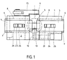
- a housing block 1 is provided at a front end 2 with a backing plate 3, which consists of two slide-shaped parts 4 and 5, which are mounted with webs 6 and 7 in a continuous, undercut guide 8 displaceable relative to each other , so that they can be moved from the retracted position shown in the drawing into the parting plane 9 of the plate 3, so that the two-part backing plate 3 is in the closed operating position.
- an arm 10 is displaceably guided relative to the backing plate 3 along a longitudinal axis 11, which lies in the division plane 9 of the backing plate 3.
- a lever 12 which can be adjusted by a drive (not shown), is articulated to the rear end of the slide-like or plunger-like arm 10 projecting from the housing block 1.
- a cylinder-shaped head 13 is mounted on the end of the arm 10 opposite the lever 12 and can be rotated about its central axis 14, which is also in the division plane 9 of the backing plate 3. Via a drive 15, which is only indicated schematically, the head 13 can be set into rotary oscillation movements of low amplitude, oscillation frequencies of approximately 200 to 300 Hertz being provided.
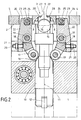
- the arm 10 In order to bring the cylindrical head 13 into the operating position, the arm 10 is moved along its longitudinal axis 11 by moving the lever 12 from its retracted position shown in FIG. 2 into the operating position against the inside of the two-part backing plate 3.
- the arm 10 is wedge-shaped or conical Provide section 16, on which rollers 17 of two adjusting levers 18 rest, which are each pivotably mounted within the housing block 1 about a fixed axis 19.
- Each adjusting lever 18 interacts with an additional lever 22 by means of an adjusting screw 20 with a counter nut 21 screwed on.
- Each of these further levers 22 is pivotally mounted about one of the two axes 19.
- each lever 22 is provided with a jaw 23 which engages in a square bush 24 which is rotatably mounted on an axis 25.
- This axis 25 is fastened in an elongated hole 26, which is provided in each of the two parts 4 and 5 of the backing plate 3.
- the wedge-shaped or conical section 16 pushes the rollers 17 of the actuating levers 18 lying against it apart, as a result of which the actuating levers 18 are pivoted about the axis 19 assigned to them.
- This pivoting movement is transmitted to the lever 22, which thereby push the parts 4 and 5 of the backing plate 3 towards one another.
- the levers 22 are set in such a way that the parts 4 and 5 of the backing plate 3 lie against one another with their respective leading edge 27 when the cylindrical head 13 is in its advanced operating position.
- the parts 4 and 5 of the backing plate 3 are each provided with an arcuate recess 28 which corresponds to the curvature of the surface of the cylindrical head 13, so that the head 13 lies in the operating position within the recesses 28 and between the surface of the head 13th and only a small gap remains on the surfaces of the recesses 28, which corresponds approximately to the thickness of the interposed, superimposed ends of a band, not shown here.
- the head 13 then becomes arcuate Vibration movements of small amplitude offset to generate the necessary heat in the superimposed ends of the thermoplastic tape and thereby bring about the welding of these ends by means of the contact pressure of the welding head 13.
- the head 13 is withdrawn.
- the levers 22 are pivoted back into the starting position shown in FIG. 2, so that the parts 4 and 5 of the backing plate 3 move apart again into the starting position.
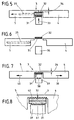
- the surfaces of the cylindrical head 13 and the arcuate recesses 28 are each provided with a roughening 29 or 30 or a corrugation, so that between the head 13 and the parts 4 and 5 of the deposit -Plate 3 ends 31 and 32 of a band are each held in frictional engagement on the surface of the head 13 and the recesses 28 in order to generate a relative movement between the ends 31 and 32 for heating these ends for a short time during the swinging movements of the head 13 and to weld the heated strip ends together under a pressure indicated by an arrow 33.
- the smallest necessary thickness 34 of the two parts 4 and 5 of the backing plate 3 is particularly small, so that the tape tension is only slightly reduced after the release of the welded ends 31 and 32 of the tape.
- the ends 31 and 32 of the band are not caused by relative frictional movements heated the welding process, but by means of a heating tongue 35 which is slidably mounted in one part 5 of the backing plate 3 in order to be able to insert it between the band ends 31 and 32.
- the heating tongue 35 is withdrawn, whereupon a pressure stamp 36 presses the heated ribbon ends 31 and 32 against one another in order to bring about the desired welding. Then the welded tape ends 31 and 32 can be released after pulling back the parts 4 and 5 of the backing plate 3.
- Fig. 6 shows that the welded tape ends 31 and 32 are moved only a small distance after the parts 4 and 5 of the backing plate 3 have been moved apart, so that the tape tension also decreases only slightly, although the minimum thickness 34 Parts 4 and 5 of the backing plate 3 in this embodiment are larger than in the embodiment according to FIGS. 3 and 4.
- the heat required for welding the band ends 31 and 32 is generated by a pressure ram 37, which in the horizontal direction according to a double arrow 38 in the direction of movement of the parts 4 and 5 indicated by arrows 39 and 40 the backing plate 3 can be moved swinging.
- the pressure stamp 37 is provided with a roughening 41, just as the parts 4 and 5 and the backing plate 3 have a roughening 42 opposite the pressure stamp, in order to achieve a frictional contact movement between the two band ends 31 and 32 can, however, to prevent these ends from moving relative to their support during the frictional contact movement.
- the smallest thickness 34 of parts 4 and 5 of the underlay plate 3 is greater than in the embodiment according to FIGS. 3 and 4, but it is nevertheless very small, as shown in FIG. 6 in connection with the embodiment according to FIG. 5 and 6 shows.
- the frequency of the relative movements between the band ends 31 and 32 to be welded to one another is relatively low in contrast to previously known high-frequency ultrasound heating.
- This frequency is approximately in the range of 200 Hertz and particularly preferably in a range between approximately 200 and approximately 300 Hertz.
Landscapes
- Engineering & Computer Science (AREA)
- Mechanical Engineering (AREA)
- Basic Packing Technique (AREA)
- Cable Accessories (AREA)
- Lining Or Joining Of Plastics Or The Like (AREA)
- Apparatus For Radiation Diagnosis (AREA)
- Mechanical Coupling Of Light Guides (AREA)
- Replacement Of Web Rolls (AREA)
Applications Claiming Priority (2)
| Application Number | Priority Date | Filing Date | Title |
|---|---|---|---|
| DE29606754U | 1996-04-13 | ||
| DE29606754U DE29606754U1 (de) | 1996-04-13 | 1996-04-13 | Vorrichtung zum Verbinden der Enden von Bändern o.dgl. |
Publications (2)
| Publication Number | Publication Date |
|---|---|
| EP0800912A1 true EP0800912A1 (fr) | 1997-10-15 |
| EP0800912B1 EP0800912B1 (fr) | 2000-12-27 |
Family
ID=8022554
Family Applications (1)
| Application Number | Title | Priority Date | Filing Date |
|---|---|---|---|
| EP97104028A Expired - Lifetime EP0800912B1 (fr) | 1996-04-13 | 1997-03-11 | Dispositif pour relier les extrémités de rubans |
Country Status (4)
| Country | Link |
|---|---|
| EP (1) | EP0800912B1 (fr) |
| AT (1) | ATE198290T1 (fr) |
| DE (2) | DE29606754U1 (fr) |
| ES (1) | ES2155222T3 (fr) |
Citations (3)
| Publication number | Priority date | Publication date | Assignee | Title |
|---|---|---|---|---|
| US4624809A (en) * | 1983-10-11 | 1986-11-25 | Yoshida Kogyo K.K. | Method and apparatus for forming upper steps of a concealed type slide fastener |
| US4743412A (en) * | 1984-08-21 | 1988-05-10 | Yoshida Kogyo K.K. | Space portion processing method and apparatus for a slide fastener chain |
| DE3911634A1 (de) * | 1989-04-10 | 1990-10-11 | Kurt Luedtke | Ultraschall-schweisssystem zum ueberlappungsschweissen von kunststoff-baendern |
-
1996
- 1996-04-13 DE DE29606754U patent/DE29606754U1/de not_active Expired - Lifetime
-
1997
- 1997-03-11 ES ES97104028T patent/ES2155222T3/es not_active Expired - Lifetime
- 1997-03-11 DE DE59702798T patent/DE59702798D1/de not_active Expired - Fee Related
- 1997-03-11 EP EP97104028A patent/EP0800912B1/fr not_active Expired - Lifetime
- 1997-03-11 AT AT97104028T patent/ATE198290T1/de not_active IP Right Cessation
Patent Citations (3)
| Publication number | Priority date | Publication date | Assignee | Title |
|---|---|---|---|---|
| US4624809A (en) * | 1983-10-11 | 1986-11-25 | Yoshida Kogyo K.K. | Method and apparatus for forming upper steps of a concealed type slide fastener |
| US4743412A (en) * | 1984-08-21 | 1988-05-10 | Yoshida Kogyo K.K. | Space portion processing method and apparatus for a slide fastener chain |
| DE3911634A1 (de) * | 1989-04-10 | 1990-10-11 | Kurt Luedtke | Ultraschall-schweisssystem zum ueberlappungsschweissen von kunststoff-baendern |
Also Published As
| Publication number | Publication date |
|---|---|
| DE29606754U1 (de) | 1996-06-27 |
| ATE198290T1 (de) | 2001-01-15 |
| EP0800912B1 (fr) | 2000-12-27 |
| DE59702798D1 (de) | 2001-02-01 |
| ES2155222T3 (es) | 2001-05-01 |
Similar Documents
| Publication | Publication Date | Title |
|---|---|---|
| DE3103973C2 (fr) | ||
| DE69301171T3 (de) | Handumreifungsvorrichtung | |
| DE4313875C2 (de) | Vorrichtung zum Herstellen von Einsteckhüllen oder Einbanddecken | |
| DE2324293B2 (de) | Vorrichtung zum Umschnüren eines Ballens o.dgl | |
| EP3419810B1 (fr) | Dispositif de cerclage comportant un dispositif de soudage par ultrasons | |
| DE4014305A1 (de) | Vorrichtung zum verbinden von sich ueberlappenden abschnitten eines thermoplastischen bandes | |
| AT392198B (de) | Vorrichtung zur behandlung von fleisch | |
| DE3423155C2 (fr) | ||
| DE2133714B2 (de) | Umreifungseinheit zum umreifen von expansiven guetern | |
| EP0095644B1 (fr) | Dispositif de fixation des extrémités qui se recouvrent d'un lieu de cerclage tendu autour d'un paquet | |
| EP0679503A1 (fr) | Procédé pour fabriquer des pièces moulées à partir de matières pulvérulentes et presse correspondante | |
| DE68925820T2 (de) | Einzelband-Formvorrichtung | |
| DE1477027C3 (de) | Vorrichtung zur Herstellung maschinell verarbeitbareNagelstreifen mit vollköpfigen und vollschäftigen Nageln | |
| DE69304141T2 (de) | Vorrichtung zum Teilen von Brotteig oder dergleichen | |
| EP3360807A1 (fr) | Dispositif de cerclage destiné au cerclage d'emballages de marchandise | |
| EP0800912B1 (fr) | Dispositif pour relier les extrémités de rubans | |
| DE19614634A1 (de) | Vorrichtung zum Verbinden der Enden von Bändern o. dgl. | |
| DE19802589A1 (de) | Vorrichtung zum schrittweisen Biegen von Metall-Bändern und/oder Blechen | |
| DE69604065T2 (de) | Zylinder für druckmaschinen | |
| DE2832357A1 (de) | Abfallpresse | |
| EP0392047A1 (fr) | Procédé et appareil pour déformer à chaud des laminés en résines synthétiques | |
| EP1619128B1 (fr) | Dispositif de compression et d'emballage | |
| DE2812394C2 (de) | Bandeinfassungsmaschine zum Umbiegen eines Bandes aus flexiblem Material um die Kante von Teilen geringer Stärke | |
| DE69611135T2 (de) | Rahmen mit Schnellspanneinrichtung für Stanzwerkzeuge | |
| DE2645243A1 (de) | Verfahren und vorrichtung zum verbinden zweier baender aus thermoplastischem werkstoff |
Legal Events
| Date | Code | Title | Description |
|---|---|---|---|
| PUAI | Public reference made under article 153(3) epc to a published international application that has entered the european phase |
Free format text: ORIGINAL CODE: 0009012 |
|
| AK | Designated contracting states |
Kind code of ref document: A1 Designated state(s): AT BE CH DE DK ES FI FR GB GR IE IT LI LU NL PT SE |
|
| 17P | Request for examination filed |
Effective date: 19980319 |
|
| RTI1 | Title (correction) |
Free format text: APPARATUS FOR JOINING TAPE ENDS |
|
| GRAG | Despatch of communication of intention to grant |
Free format text: ORIGINAL CODE: EPIDOS AGRA |
|
| 17Q | First examination report despatched |
Effective date: 20000322 |
|
| GRAG | Despatch of communication of intention to grant |
Free format text: ORIGINAL CODE: EPIDOS AGRA |
|
| GRAH | Despatch of communication of intention to grant a patent |
Free format text: ORIGINAL CODE: EPIDOS IGRA |
|
| GRAH | Despatch of communication of intention to grant a patent |
Free format text: ORIGINAL CODE: EPIDOS IGRA |
|
| GRAA | (expected) grant |
Free format text: ORIGINAL CODE: 0009210 |
|
| AK | Designated contracting states |
Kind code of ref document: B1 Designated state(s): AT BE CH DE DK ES FI FR GB GR IE IT LI LU NL PT SE |
|
| PG25 | Lapsed in a contracting state [announced via postgrant information from national office to epo] |
Ref country code: SE Free format text: THE PATENT HAS BEEN ANNULLED BY A DECISION OF A NATIONAL AUTHORITY Effective date: 20001227 Ref country code: IE Free format text: LAPSE BECAUSE OF FAILURE TO SUBMIT A TRANSLATION OF THE DESCRIPTION OR TO PAY THE FEE WITHIN THE PRESCRIBED TIME-LIMIT Effective date: 20001227 Ref country code: FI Free format text: LAPSE BECAUSE OF FAILURE TO SUBMIT A TRANSLATION OF THE DESCRIPTION OR TO PAY THE FEE WITHIN THE PRESCRIBED TIME-LIMIT Effective date: 20001227 |
|
| REF | Corresponds to: |
Ref document number: 198290 Country of ref document: AT Date of ref document: 20010115 Kind code of ref document: T |
|
| REG | Reference to a national code |
Ref country code: CH Ref legal event code: EP |
|
| REF | Corresponds to: |
Ref document number: 59702798 Country of ref document: DE Date of ref document: 20010201 |
|
| REG | Reference to a national code |
Ref country code: IE Ref legal event code: FG4D Free format text: GERMAN |
|
| PG25 | Lapsed in a contracting state [announced via postgrant information from national office to epo] |
Ref country code: LU Free format text: LAPSE BECAUSE OF NON-PAYMENT OF DUE FEES Effective date: 20010311 |
|
| ITF | It: translation for a ep patent filed | ||
| PG25 | Lapsed in a contracting state [announced via postgrant information from national office to epo] |
Ref country code: PT Free format text: LAPSE BECAUSE OF FAILURE TO SUBMIT A TRANSLATION OF THE DESCRIPTION OR TO PAY THE FEE WITHIN THE PRESCRIBED TIME-LIMIT Effective date: 20010327 Ref country code: DK Free format text: LAPSE BECAUSE OF FAILURE TO SUBMIT A TRANSLATION OF THE DESCRIPTION OR TO PAY THE FEE WITHIN THE PRESCRIBED TIME-LIMIT Effective date: 20010327 |
|
| PG25 | Lapsed in a contracting state [announced via postgrant information from national office to epo] |
Ref country code: GR Free format text: LAPSE BECAUSE OF FAILURE TO SUBMIT A TRANSLATION OF THE DESCRIPTION OR TO PAY THE FEE WITHIN THE PRESCRIBED TIME-LIMIT Effective date: 20010330 |
|
| GBT | Gb: translation of ep patent filed (gb section 77(6)(a)/1977) |
Effective date: 20010323 |
|
| ET | Fr: translation filed | ||
| REG | Reference to a national code |
Ref country code: ES Ref legal event code: FG2A Ref document number: 2155222 Country of ref document: ES Kind code of ref document: T3 |
|
| REG | Reference to a national code |
Ref country code: CH Ref legal event code: NV Representative=s name: A. BRAUN, BRAUN, HERITIER, ESCHMANN AG PATENTANWAE |
|
| PLBE | No opposition filed within time limit |
Free format text: ORIGINAL CODE: 0009261 |
|
| STAA | Information on the status of an ep patent application or granted ep patent |
Free format text: STATUS: NO OPPOSITION FILED WITHIN TIME LIMIT |
|
| REG | Reference to a national code |
Ref country code: IE Ref legal event code: FD4D |
|
| 26N | No opposition filed | ||
| REG | Reference to a national code |
Ref country code: GB Ref legal event code: IF02 |
|
| PGFP | Annual fee paid to national office [announced via postgrant information from national office to epo] |
Ref country code: BE Payment date: 20020131 Year of fee payment: 6 |
|
| PGFP | Annual fee paid to national office [announced via postgrant information from national office to epo] |
Ref country code: GB Payment date: 20020227 Year of fee payment: 6 |
|
| PGFP | Annual fee paid to national office [announced via postgrant information from national office to epo] |
Ref country code: FR Payment date: 20020321 Year of fee payment: 6 Ref country code: AT Payment date: 20020321 Year of fee payment: 6 |
|
| PGFP | Annual fee paid to national office [announced via postgrant information from national office to epo] |
Ref country code: CH Payment date: 20020325 Year of fee payment: 6 |
|
| PGFP | Annual fee paid to national office [announced via postgrant information from national office to epo] |
Ref country code: NL Payment date: 20020328 Year of fee payment: 6 |
|
| PGFP | Annual fee paid to national office [announced via postgrant information from national office to epo] |
Ref country code: ES Payment date: 20020416 Year of fee payment: 6 |
|
| PGFP | Annual fee paid to national office [announced via postgrant information from national office to epo] |
Ref country code: DE Payment date: 20020527 Year of fee payment: 6 |
|
| PG25 | Lapsed in a contracting state [announced via postgrant information from national office to epo] |
Ref country code: GB Free format text: LAPSE BECAUSE OF NON-PAYMENT OF DUE FEES Effective date: 20030311 Ref country code: AT Free format text: LAPSE BECAUSE OF NON-PAYMENT OF DUE FEES Effective date: 20030311 |
|
| PG25 | Lapsed in a contracting state [announced via postgrant information from national office to epo] |
Ref country code: ES Free format text: LAPSE BECAUSE OF NON-PAYMENT OF DUE FEES Effective date: 20030312 |
|
| PG25 | Lapsed in a contracting state [announced via postgrant information from national office to epo] |
Ref country code: LI Free format text: LAPSE BECAUSE OF NON-PAYMENT OF DUE FEES Effective date: 20030331 Ref country code: CH Free format text: LAPSE BECAUSE OF NON-PAYMENT OF DUE FEES Effective date: 20030331 Ref country code: BE Free format text: LAPSE BECAUSE OF NON-PAYMENT OF DUE FEES Effective date: 20030331 |
|
| BERE | Be: lapsed |
Owner name: MASCHINENBAU *GEROLD G.M.B.H. + CO. K.G. Effective date: 20030331 |
|
| PG25 | Lapsed in a contracting state [announced via postgrant information from national office to epo] |
Ref country code: NL Free format text: LAPSE BECAUSE OF NON-PAYMENT OF DUE FEES Effective date: 20031001 Ref country code: DE Free format text: LAPSE BECAUSE OF NON-PAYMENT OF DUE FEES Effective date: 20031001 |
|
| GBPC | Gb: european patent ceased through non-payment of renewal fee |
Effective date: 20030311 |
|
| REG | Reference to a national code |
Ref country code: CH Ref legal event code: PL |
|
| PG25 | Lapsed in a contracting state [announced via postgrant information from national office to epo] |
Ref country code: FR Free format text: LAPSE BECAUSE OF NON-PAYMENT OF DUE FEES Effective date: 20031127 |
|
| NLV4 | Nl: lapsed or anulled due to non-payment of the annual fee |
Effective date: 20031001 |
|
| REG | Reference to a national code |
Ref country code: FR Ref legal event code: ST |
|
| REG | Reference to a national code |
Ref country code: ES Ref legal event code: FD2A Effective date: 20030312 |
|
| PG25 | Lapsed in a contracting state [announced via postgrant information from national office to epo] |
Ref country code: IT Free format text: LAPSE BECAUSE OF NON-PAYMENT OF DUE FEES;WARNING: LAPSES OF ITALIAN PATENTS WITH EFFECTIVE DATE BEFORE 2007 MAY HAVE OCCURRED AT ANY TIME BEFORE 2007. THE CORRECT EFFECTIVE DATE MAY BE DIFFERENT FROM THE ONE RECORDED. Effective date: 20050311 |