EP0800969A2 - Dispositif de réglage d'un renvoi - Google Patents
Dispositif de réglage d'un renvoi Download PDFInfo
- Publication number
- EP0800969A2 EP0800969A2 EP97105241A EP97105241A EP0800969A2 EP 0800969 A2 EP0800969 A2 EP 0800969A2 EP 97105241 A EP97105241 A EP 97105241A EP 97105241 A EP97105241 A EP 97105241A EP 0800969 A2 EP0800969 A2 EP 0800969A2
- Authority
- EP
- European Patent Office
- Prior art keywords
- rail
- adjusting device
- pawl
- parallelepiped
- vehicle
- Prior art date
- Legal status (The legal status is an assumption and is not a legal conclusion. Google has not performed a legal analysis and makes no representation as to the accuracy of the status listed.)
- Granted
Links
Images
Classifications
-
- B—PERFORMING OPERATIONS; TRANSPORTING
- B60—VEHICLES IN GENERAL
- B60R—VEHICLES, VEHICLE FITTINGS, OR VEHICLE PARTS, NOT OTHERWISE PROVIDED FOR
- B60R22/00—Safety belts or body harnesses in vehicles
- B60R22/18—Anchoring devices
- B60R22/20—Anchoring devices adjustable in position, e.g. in height
- B60R22/201—Anchoring devices adjustable in position, e.g. in height with the belt anchor connected to a slider movable in a vehicle-mounted track
- B60R22/205—Anchoring devices adjustable in position, e.g. in height with the belt anchor connected to a slider movable in a vehicle-mounted track the slider comprising emergency actuated locking means
-
- B—PERFORMING OPERATIONS; TRANSPORTING
- B60—VEHICLES IN GENERAL
- B60R—VEHICLES, VEHICLE FITTINGS, OR VEHICLE PARTS, NOT OTHERWISE PROVIDED FOR
- B60R22/00—Safety belts or body harnesses in vehicles
- B60R22/18—Anchoring devices
- B60R22/20—Anchoring devices adjustable in position, e.g. in height
Definitions
- the invention relates to an adjusting device for a deflection fitting of a vehicle seat belt system, having a rail which is fixed to the vehicle and provided with latching openings and a slide which can be displaced therein and which is provided for attaching the deflecting fitting and is provided with a latching mechanism which can interact with the latching openings.
- Such an adjustment device is used to optimally adapt the course of the seat belt to the size of the respective vehicle occupant. Problems with the use of such an adjustment device can arise if the slide is between two locking openings in the event of an accident, that is to say that it is not secured to a locking opening by means of the locking mechanism. This problem is exacerbated if the seat belt system is provided with a belt tensioner which pulls the belt loops out of the seat belt system in the event of an accident. The forces acting on the deflecting fitting can result in the locking mechanism not being securely inserted into the next one Interlocking opening engages and therefore the carriage is moved downwards relative to the vehicle, which affects the effect of the belt tensioner.
- Locking mechanisms are therefore known which are also intended to ensure secure engagement in the next following locking opening even when the slide is accelerated downward very strongly relative to the vehicle.
- the effect of the belt tensioner is impaired by the path that the carriage covers until the locking mechanism engages in the next locking opening.
- a locking element which is functionally independent of the latching mechanism is mounted on the slide in such a way that from a rest position, in which it does not act on the rail, by means of an action acting on the slide, Downward acceleration relative to the vehicle can be moved into a locking position in which it engages the rail and fixes the carriage.
- the locking element blocks the carriage after a movement of a few millimeters, so that almost no additional belt loops are generated if the latching mechanism does not properly engage in a latching opening.
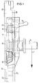
- FIG. 1 shows a first embodiment of an adjustment device according to the invention.
- the adjusting device contains a rail 10 fixed to the vehicle, in which a slide 12 is slidably arranged, to which a bolt 14 for attaching a deflection fitting (not shown) is attached.
- the rail consists of a base part 10 1 , two side parts 10 2 perpendicular to this and two front parts 10 3 opposite the base part 10 1 and extending from the side parts.
- a latch mechanism 16 which is only indicated schematically, is provided, by the actuation of which the carriage 12 can be moved up and down in the longitudinal direction of the rail relative to the vehicle.
- the locking mechanism 16 has a bolt 18 which can engage in locking openings 20 so that the carriage 12 is fixed relative to the rail 10.
- the carriage 12 is shown in an operating position which is undesirable per se, but which cannot be reliably prevented in practice.
- the bolt 18 is located slightly below a locking opening 20 so that it cannot engage in it. If, in this position, a downward force acts on the slide 12 via the deflection fitting, which is symbolized by the arrow F and can originate from the tensioning effect of a belt tensioner which pulls the belt slack out of the seat belt, the slide 12 would extend at least up to Move the next latch opening 20 down. This would lead to an additional belt slack in the seat belt, which is disadvantageous for the restraining effect of the seat belt.
- the adjusting device In order to prevent such a downward movement of the slide 12, the adjusting device according to the invention is provided with a locking element 22 which is functionally independent of the locking mechanism 16. This is mounted on the slide 12 in the interior of the rail 10 such that it can be moved to the slide 12 to a limited extent in the longitudinal direction of the rail 10 and can also be rotated about its center of gravity.
- the locking element 22 has the shape of an oblique parallelepiped, of which two side surfaces are parallel to the bottom part 10 1 or the front parts 10 3 of the rail 10 and to the side parts 10 2 of the rail 10.
- the inertia of the blocking element 22 causes a relative movement between the blocking element 22 and the carriage 12, so that the carriage on the upper edge of the blocking element 22 with respect to FIG. 1 , eccentric in terms of its focus.
- the locking element 22 wedges between the bottom part 101 and the front parts 10 3 of the rail, so that a movement of the carriage 12 downward is stopped after a distance of a few millimeters.
- the tensioning effect of a belt tensioner is therefore almost not impaired by an additional belt slack, even if the carriage 12 is in the unfavorable operating position shown in FIG. 1.
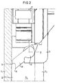
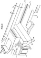
- FIGS. 2 and 3 show a second embodiment of an adjustment device according to the invention.
- elements known from FIG. 1 are provided with the same reference symbols; with regard to their function, reference is made to the explanation of FIG. 1.
- the locking element in contrast to the first embodiment, in the second embodiment the locking element consists of a locking pawl 30.
- This locking pawl 30 is pivotable about an axis lying outside its center of gravity and perpendicular to the side parts 10 2 of the rail 10 on a support side 32 facing the front parts 10 3
- the pawl 30 On its side facing the bottom part 10 1 , the pawl 30 is provided with an engagement edge 36 and a support edge 38 parallel to this.
- the outer contour of the pawl 30, seen in a cross section perpendicular to the pivot axis, has an arcuate shape at the support end 32 and between the support side 32 and the support edge 38 on the bottom directed side a constriction, so that a pivot bearing is formed together with the bearing part 34.
- the invention thus provides an adjustment device in which, in a reliable and structurally particularly simple manner, a downward movement of the slide is blocked within a few millimeters if the locking mechanism does not properly engage in a locking opening and the slide is accelerated downward.
- the locking element is an easily manufactured metal part that can be punched or sintered.
Landscapes
- Engineering & Computer Science (AREA)
- Mechanical Engineering (AREA)
- Automotive Seat Belt Assembly (AREA)
- Seats For Vehicles (AREA)
- Lighting Device Outwards From Vehicle And Optical Signal (AREA)
Applications Claiming Priority (2)
| Application Number | Priority Date | Filing Date | Title |
|---|---|---|---|
| DE29606521U DE29606521U1 (de) | 1996-04-10 | 1996-04-10 | Verstellvorrichtung für einen Umlenkbeschlag |
| DE29606521U | 1996-04-10 |
Publications (3)
| Publication Number | Publication Date |
|---|---|
| EP0800969A2 true EP0800969A2 (fr) | 1997-10-15 |
| EP0800969A3 EP0800969A3 (fr) | 2000-12-27 |
| EP0800969B1 EP0800969B1 (fr) | 2005-05-04 |
Family
ID=8022377
Family Applications (1)
| Application Number | Title | Priority Date | Filing Date |
|---|---|---|---|
| EP97105241A Expired - Lifetime EP0800969B1 (fr) | 1996-04-10 | 1997-03-27 | Dispositif de réglage d'un renvoi |
Country Status (6)
| Country | Link |
|---|---|
| US (1) | US5857704A (fr) |
| EP (1) | EP0800969B1 (fr) |
| JP (1) | JP2981440B2 (fr) |
| KR (1) | KR100247680B1 (fr) |
| DE (2) | DE29606521U1 (fr) |
| ES (1) | ES2108674T3 (fr) |
Families Citing this family (4)
| Publication number | Priority date | Publication date | Assignee | Title |
|---|---|---|---|---|
| DE29700549U1 (de) * | 1997-01-14 | 1997-05-07 | Trw Occupant Restraint Systems Gmbh, 73551 Alfdorf | Verstellvorrichtung für einen Umlenkbeschlag eines Fahrzeug-Sicherheitsgurtsystems |
| DE29805083U1 (de) | 1998-03-20 | 1998-07-23 | TRW Occupant Restraint Systems GmbH & Co. KG, 73553 Alfdorf | Verstellvorrichtung für einen Umlenkbeschlag |
| DE102011014175B4 (de) * | 2011-03-16 | 2021-05-12 | Autoliv Development Ab | Höhenversteller für einen Befestigungsbeschlag eines Sicherheitsgurt-Systems |
| WO2022187825A1 (fr) * | 2021-03-02 | 2022-09-09 | Indiana Mills & Manufacturing, Inc. | Dispositif de réglage de ceinture intermédiaire à libération de levier |
Family Cites Families (10)
| Publication number | Priority date | Publication date | Assignee | Title |
|---|---|---|---|---|
| US4466666A (en) * | 1981-04-27 | 1984-08-21 | Juichiro Takada | Seat belt anchor assembly |
| US4538832A (en) * | 1983-02-14 | 1985-09-03 | Ase (Uk) Limited | Adjustable seat belt anchorage |
| DE3706367A1 (de) * | 1987-02-27 | 1988-09-08 | Daimler Benz Ag | Vorrichtung zur selbsttaetigen hoehenverstellung des umlenkbeschlages eines sicherheitsgurtes in fahrzeugen |
| JPH0771920B2 (ja) * | 1988-04-25 | 1995-08-02 | 株式会社東海理化電機製作所 | 支持高さ可変式ウエビング支持装置 |
| DE3844258A1 (de) * | 1988-12-29 | 1990-07-12 | Autoliv Kolb Gmbh & Co Kg | Hoehenverstellbarer umlenkbeschlag fuer sicherheitsgurte von kraftfahrzeugen |
| DE4011767C2 (de) * | 1990-04-11 | 1997-02-13 | Autoliv Kolb Gmbh & Co | Höhenverstellbarer Umlenkbeschlag für einen Sicherheitsgurt eines Kfz |
| FR2664549B1 (fr) * | 1990-07-13 | 1995-05-12 | Autoliv Klippan Snc | Dispositif de reglage de position pour renvoi de sangle, et ceinture de securite ainsi equipee. |
| GB2263054B (en) * | 1991-12-23 | 1995-12-06 | Gen Engineering | Improvements in or relating to a safety belt arrangement |
| US5265908A (en) * | 1992-03-16 | 1993-11-30 | Trw Vehicle Safety Systems Inc. | Height adjuster for D-ring |
| DE4327820A1 (de) * | 1993-08-19 | 1995-02-23 | Autoliv Dev | Strammertauglicher höhenverstellbarer Umlenkbeschlag |
-
1996
- 1996-04-10 DE DE29606521U patent/DE29606521U1/de not_active Expired - Lifetime
-
1997
- 1997-03-27 DE DE59712293T patent/DE59712293D1/de not_active Expired - Fee Related
- 1997-03-27 ES ES97105241T patent/ES2108674T3/es not_active Expired - Lifetime
- 1997-03-27 EP EP97105241A patent/EP0800969B1/fr not_active Expired - Lifetime
- 1997-04-08 US US08/835,455 patent/US5857704A/en not_active Expired - Fee Related
- 1997-04-08 KR KR1019970012780A patent/KR100247680B1/ko not_active Expired - Fee Related
- 1997-04-09 JP JP9090920A patent/JP2981440B2/ja not_active Expired - Fee Related
Also Published As
| Publication number | Publication date |
|---|---|
| US5857704A (en) | 1999-01-12 |
| EP0800969B1 (fr) | 2005-05-04 |
| EP0800969A3 (fr) | 2000-12-27 |
| DE29606521U1 (de) | 1996-08-08 |
| JP2981440B2 (ja) | 1999-11-22 |
| DE59712293D1 (de) | 2005-06-09 |
| ES2108674T1 (es) | 1998-01-01 |
| JPH1029502A (ja) | 1998-02-03 |
| ES2108674T3 (es) | 2005-10-16 |
| KR100247680B1 (ko) | 2000-05-01 |
| KR970069660A (ko) | 1997-11-07 |
Similar Documents
| Publication | Publication Date | Title |
|---|---|---|
| DE2719325C2 (de) | Verschluss für Sicherheitsgurte | |
| DE2826286C2 (de) | Sicherheitsgurtaufrollautomat | |
| DE2600613A1 (de) | Umlenkvorrichtung fuer sicherheitsgurt | |
| DE3447817A1 (de) | Hoehenverstelleinrichtung fuer den umlenkbeschlag eines sicherheitsgurtes | |
| EP0188480B1 (fr) | Dispositif de serrage de sangle pour des ceintures de securite de vehicule | |
| DE19801268C2 (de) | Sitzgurtführungshöhenverstellung | |
| EP0805075B1 (fr) | Dispositif de réglage d'un renvoi de ceinture | |
| EP0800969A2 (fr) | Dispositif de réglage d'un renvoi | |
| EP0800968B1 (fr) | Dispositif de réglage en hauteur d'un système de sécurité pour véhicule | |
| EP0370402B1 (fr) | Dispositif de réglage en hauteur d'une ferrure de ceinture de sécurité | |
| EP0257604B1 (fr) | Ferrure de renvoi à pince de blocage | |
| DE3229304C2 (de) | Rückstrammer für ein Sicherheitsgurtsystem für Kraftfahrzeuge | |
| DE4423971C2 (de) | Verriegelungsvorrichtung für Fahrzeugsitze, insbesondere Kraftfahrzeugsitze | |
| EP0853028B1 (fr) | Dispositif de réglage du renvoi latéral d'un système de ceinture de sécurité de véhicule | |
| DE4007916C2 (fr) | ||
| DE3706367C2 (fr) | ||
| DE3524121A1 (de) | Hoehenverstellbarer befestigungs- oder umlenkbeschlag | |
| DE68908311T2 (de) | Schloss für ein Sicherheitsgurtsystem. | |
| DE3516059C2 (de) | Höhenverstellvorrichtung für einen Umlenk- oder Befestigungsbeschlag | |
| DE10045185A1 (de) | Verschluß, insbesondere Gurtschloß | |
| DE29908320U1 (de) | Höhenverstellvorrichtung für Gurtbeschlag | |
| EP0140366A2 (fr) | Dispositif enrouleur pour ceintures de sécurité | |
| DE3743336C2 (de) | Verschluss fuer sicherheitsgurte und rueckhaltesysteme, insbesondere fuer verkehrsmittel | |
| DE3606912C2 (fr) | ||
| DE3014300A1 (de) | Kraftfahrzeugsitz |
Legal Events
| Date | Code | Title | Description |
|---|---|---|---|
| PUAI | Public reference made under article 153(3) epc to a published international application that has entered the european phase |
Free format text: ORIGINAL CODE: 0009012 |
|
| AK | Designated contracting states |
Kind code of ref document: A2 Designated state(s): DE ES FR GB IT |
|
| ITCL | It: translation for ep claims filed |
Representative=s name: DR. ING. A. RACHELI & C. |
|
| GBC | Gb: translation of claims filed (gb section 78(7)/1977) | ||
| REG | Reference to a national code |
Ref country code: ES Ref legal event code: BA2A Ref document number: 2108674 Country of ref document: ES Kind code of ref document: T1 |
|
| EL | Fr: translation of claims filed | ||
| RAP1 | Party data changed (applicant data changed or rights of an application transferred) |
Owner name: TRW OCCUPANT RESTRAINT SYSTEMS GMBH & CO. KG |
|
| PUAL | Search report despatched |
Free format text: ORIGINAL CODE: 0009013 |
|
| AK | Designated contracting states |
Kind code of ref document: A3 Designated state(s): DE ES FR GB IT |
|
| 17P | Request for examination filed |
Effective date: 20010222 |
|
| 17Q | First examination report despatched |
Effective date: 20020917 |
|
| GRAP | Despatch of communication of intention to grant a patent |
Free format text: ORIGINAL CODE: EPIDOSNIGR1 |
|
| GRAS | Grant fee paid |
Free format text: ORIGINAL CODE: EPIDOSNIGR3 |
|
| GRAA | (expected) grant |
Free format text: ORIGINAL CODE: 0009210 |
|
| PGFP | Annual fee paid to national office [announced via postgrant information from national office to epo] |
Ref country code: FR Payment date: 20050322 Year of fee payment: 9 |
|
| RAP1 | Party data changed (applicant data changed or rights of an application transferred) |
Owner name: TRW AUTOMOTIVE GMBH |
|
| AK | Designated contracting states |
Kind code of ref document: B1 Designated state(s): DE ES FR GB IT |
|
| REG | Reference to a national code |
Ref country code: GB Ref legal event code: FG4D Free format text: NOT ENGLISH |
|
| REF | Corresponds to: |
Ref document number: 59712293 Country of ref document: DE Date of ref document: 20050609 Kind code of ref document: P |
|
| GBT | Gb: translation of ep patent filed (gb section 77(6)(a)/1977) |
Effective date: 20050711 |
|
| REG | Reference to a national code |
Ref country code: ES Ref legal event code: FG2A Ref document number: 2108674 Country of ref document: ES Kind code of ref document: T3 |
|
| PLBE | No opposition filed within time limit |
Free format text: ORIGINAL CODE: 0009261 |
|
| STAA | Information on the status of an ep patent application or granted ep patent |
Free format text: STATUS: NO OPPOSITION FILED WITHIN TIME LIMIT |
|
| PG25 | Lapsed in a contracting state [announced via postgrant information from national office to epo] |
Ref country code: GB Free format text: LAPSE BECAUSE OF NON-PAYMENT OF DUE FEES Effective date: 20060327 |
|
| PG25 | Lapsed in a contracting state [announced via postgrant information from national office to epo] |
Ref country code: ES Free format text: LAPSE BECAUSE OF NON-PAYMENT OF DUE FEES Effective date: 20060328 |
|
| ET | Fr: translation filed | ||
| PGFP | Annual fee paid to national office [announced via postgrant information from national office to epo] |
Ref country code: IT Payment date: 20060331 Year of fee payment: 10 |
|
| 26N | No opposition filed |
Effective date: 20060207 |
|
| PG25 | Lapsed in a contracting state [announced via postgrant information from national office to epo] |
Ref country code: DE Free format text: LAPSE BECAUSE OF NON-PAYMENT OF DUE FEES Effective date: 20061003 |
|
| GBPC | Gb: european patent ceased through non-payment of renewal fee |
Effective date: 20060327 |
|
| REG | Reference to a national code |
Ref country code: FR Ref legal event code: ST Effective date: 20061130 |
|
| REG | Reference to a national code |
Ref country code: ES Ref legal event code: FD2A Effective date: 20060328 |
|
| PG25 | Lapsed in a contracting state [announced via postgrant information from national office to epo] |
Ref country code: FR Free format text: LAPSE BECAUSE OF NON-PAYMENT OF DUE FEES Effective date: 20060331 |
|
| PG25 | Lapsed in a contracting state [announced via postgrant information from national office to epo] |
Ref country code: IT Free format text: LAPSE BECAUSE OF NON-PAYMENT OF DUE FEES Effective date: 20070327 |