EP0801183A1 - Rauchabzugsvorrichtung für ein langes Tonnengewölbe - Google Patents
Rauchabzugsvorrichtung für ein langes Tonnengewölbe Download PDFInfo
- Publication number
- EP0801183A1 EP0801183A1 EP97400843A EP97400843A EP0801183A1 EP 0801183 A1 EP0801183 A1 EP 0801183A1 EP 97400843 A EP97400843 A EP 97400843A EP 97400843 A EP97400843 A EP 97400843A EP 0801183 A1 EP0801183 A1 EP 0801183A1
- Authority
- EP
- European Patent Office
- Prior art keywords
- arch
- curb
- outlet
- profile
- fixed
- Prior art date
- Legal status (The legal status is an assumption and is not a legal conclusion. Google has not performed a legal analysis and makes no representation as to the accuracy of the status listed.)
- Granted
Links
- 239000003517 fume Substances 0.000 title description 2
- 238000013022 venting Methods 0.000 title 1
- 241000239290 Araneae Species 0.000 claims description 19
- 239000000779 smoke Substances 0.000 claims description 12
- 125000006850 spacer group Chemical group 0.000 claims description 12
- 230000005540 biological transmission Effects 0.000 claims description 10
- 238000000605 extraction Methods 0.000 description 4
- 101150097977 arch-1 gene Proteins 0.000 description 3
- 230000033228 biological regulation Effects 0.000 description 3
- 230000000694 effects Effects 0.000 description 3
- 238000009423 ventilation Methods 0.000 description 3
- 238000004873 anchoring Methods 0.000 description 2
- 238000006073 displacement reaction Methods 0.000 description 2
- 238000012986 modification Methods 0.000 description 2
- 230000004048 modification Effects 0.000 description 2
- 238000007664 blowing Methods 0.000 description 1
- 230000002301 combined effect Effects 0.000 description 1
- 238000010276 construction Methods 0.000 description 1
- 230000007423 decrease Effects 0.000 description 1
- 230000000149 penetrating effect Effects 0.000 description 1
- 229920000515 polycarbonate Polymers 0.000 description 1
- 239000004417 polycarbonate Substances 0.000 description 1
- 229920000728 polyester Polymers 0.000 description 1
- 230000000284 resting effect Effects 0.000 description 1
Images
Classifications
-
- E—FIXED CONSTRUCTIONS
- E04—BUILDING
- E04D—ROOF COVERINGS; SKY-LIGHTS; GUTTERS; ROOF-WORKING TOOLS
- E04D13/00—Special arrangements or devices in connection with roof coverings; Protection against birds; Roof drainage ; Sky-lights
- E04D13/03—Sky-lights; Domes; Ventilating sky-lights
- E04D13/035—Sky-lights; Domes; Ventilating sky-lights characterised by having movable parts
- E04D13/0358—Sky-lights; Domes; Ventilating sky-lights characterised by having movable parts the parts moving, in their own plane, e.g. rolling or sliding, or moving in parallel planes with or without an additional movement, e.g. both pivoting and rolling or sliding
-
- E—FIXED CONSTRUCTIONS
- E04—BUILDING
- E04D—ROOF COVERINGS; SKY-LIGHTS; GUTTERS; ROOF-WORKING TOOLS
- E04D13/00—Special arrangements or devices in connection with roof coverings; Protection against birds; Roof drainage ; Sky-lights
- E04D13/03—Sky-lights; Domes; Ventilating sky-lights
- E04D13/032—Supports or connecting means for sky-lights of vaulted shape
-
- F—MECHANICAL ENGINEERING; LIGHTING; HEATING; WEAPONS; BLASTING
- F24—HEATING; RANGES; VENTILATING
- F24F—AIR-CONDITIONING; AIR-HUMIDIFICATION; VENTILATION; USE OF AIR CURRENTS FOR SCREENING
- F24F7/00—Ventilation
- F24F7/02—Roof ventilation
Definitions
- the present invention relates to a smoke vent for an elongated self-supporting curved vault carried by two curbs extending in a longitudinal direction of the vault.
- arch elements are made of ribbed polyester elements, which partially overlap each other at a rib.
- Other arch elements consist of extruded polycarbonate plates, two adjacent plates being pinched between two arches, one upper, the other lower, carrying the plates.
- outlets include arch half-elements extending substantially over half of the transverse width of the arch, articulated along one of their longitudinal edges, for example the edge along the curb. corresponding, and are actuated by jacks so as to release the opening formed in the vault substantially completely.
- the outlet comprises at least one arch element extending substantially over the entire width of the arch and movable with respect thereto, and means forming a jack for lifting one side of this arch element so as to move said arch element towards its extended position to open the outlet, or to lower said side so as to bring the movable arch element into its retracted position substantially in alignment with the other fixed arch elements, to close the outlet.
- Such an arch element does not allow compliance with the regulations in force. It is extremely difficult to prevent a wind blowing towards the open side of this arch element from driving the smoke to be evacuated towards the interior of the building. It has been proposed to place screens in front of this open side. These screens are bulky, expensive, fragile, unattractive and their presence decreases so important the aeraulic characteristics of this device.
- the object of the present invention is to remedy the drawbacks of known devices, and to propose a smoke extraction outlet with a simple, reliable and economical structure, easy to install and to use.
- Such an outlet open on four sides and moved vertically above the opening of the roof, has air flow characteristics in accordance with the regulations in force, as soon as the opening of the movable roof element is sufficient.
- the movable arch element prevents rain from entering the outlet.
- this outlet presents no risk of smoke backflow for a wind directed in the longitudinal direction or in the transverse direction of the roof.
- this outlet does not present any risk of smoke backflow for a wind directed in the direction of a diagonal of the outlet.
- the movable arch element of the outlet according to the invention has a relatively low wind resistance while having excellent stability and good mechanical resistance due to the fact that the vertical distance of the movable arch element in position high above the adjacent fixed arch elements is relatively low compared to longitudinal and transverse dimensions of said movable arch element.
- the outlet comprises a slide element fixed on the inner face of the corresponding curb facing the other curb, and extending substantially over the entire longitudinal dimension of the movable arch element. so as to be located below the corresponding profile in the closed position of the arch element, and the guide means comprise two cross-pieces hinged with respect to each other so as to pivot around a transverse axis by relative to the arch and pivotally fixed around respective transverse axes at their end situated on the same side of the arch element with respect to said longitudinal direction, the first cross to the slide element, the second cross to the profile longitudinal, the two cross-pieces comprising at their free end a member adapted to slide respectively, for the first cross-piece the lon g of the longitudinal section, for the second crosspiece along the slide element.
- the outlet comprises two jacks directed substantially along a perpendicular to the plane defined by the longitudinal edges of the opening closed by said outlet, each jack being fixed on the one hand to the slide element , on the other hand to the corresponding longitudinal profile, in the vicinity of the end of these opposite the transverse pivot axes of the braces, and the two braces articulated respectively on the elements forming slideways are connected to each other by a transmission shaft arranged along their aligned pivot axes.
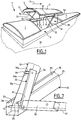
- FIG. 1 represents an elongated self-supporting curved vault 1 carried by two parallel curbs 2 extending in a longitudinal direction 3 of the vault 1.
- the vault 1 comprises in this example a smoke extraction vent 4 which comprises at least one vault element 5 extending substantially over the entire width of the latter and movable relative thereto.
- the outlet 4 also includes at least one jack 6 for lifting the arch element 5 to its extended position shown in the figure, for fully opening the outlet 4, or for lowering said arch element 5 in its retracted position substantially in alignment with the other fixed arch elements 7, to close the outlet 4.
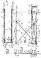
- the crossbars 12, 13 are thus adapted to keep the profile 10 parallel to the corresponding curb 2 when the movable arch element is moved by the jack 6.
- the two crossbars 12, 13 are articulated with respect to each other substantially in the middle.
- Each profile 10 is substantially adjacent to the inner face 9 of the corresponding curb 2 facing the other curb 2, in the closed position of the arch element 5.
- the outlet 4 comprises two jacks 6 directed vertically, that is to say according to a perpendicular to the horizontal plane defined by the roof 19 or the two profiles 10 or the upper edges 20 of the two curbs 2, therefore to the plane defined by the longitudinal edges 20 of the opening 35 closed by the outlet 4.
- Each cylinder 6 is fixed, in the vicinity of the corresponding curb 2, on the one hand to the slide 8, on the other hand to the corresponding longitudinal section 10, in the vicinity of the end of these opposite the pivot axes 15, 16 respective crossbars 12,13.
- each profile 10 is held at three points: the axis 16 of pivoting of the cross 13, at the end of the profile 10 located to the left of the figure, at point 21 of anchoring of the rod 6a of the actuator 6 on said profile, at the level of the sliding member 17 at the free end 12b of the spider 12, this member being all the more distant from the anchoring point 21 as the arch element mobile 5 is closer to its extended position.
- the slide 8 comprises a profile 22 of rectangular section open at its upper part in a longitudinal groove 23 crossed by the cross 13 whose end 13b carries rollers 43 which roll on the bottom of the slide 8, and by the cross member 12 pivotally mounted around the axis 15.
- the profile 10 is a profile substantially identical to the profile 22 of the slide 8.
- the longitudinal groove 24 of the profile 10 is directed downwards and is crossed by the spider 12 whose upper end 12b carries rollers 43 which roll on the edges 25 and 26 of the groove 24.
- the groove 23 of the profile 22 has the same edges 25 and 26.
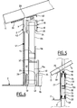
- the slide 8 comprises, on either side of the profile 22 of the longitudinal sheets 27, 28 which form, with vertical end profiles 29, 30, a box adapted to contain the crossbars 12, 13 in their folded position, the profile 10 resting on the end profiles 29-30 (See Figure 3).
- the slide 8 can thus be easily transported when assembled, and then fixed to the inner face 9 of the corresponding curb 2.
- the two cross-pieces 12 articulated respectively on the profiles 22 of the slides 8 are connected to each other by a transmission shaft 31 disposed along their pivot axes 15 aligned.
- This transmission shaft 31 is thus a coordination means adapted to maintain the profiles 10 on each side of the vault in a plane parallel to the plane defined by the longitudinal edges of the opening 35 formed by the outlet.
- each cross member 12 comprises a connecting rod 32 having an end 36 integral in rotation with the transmission shaft 31 and adapted to pivot around the axis of rotation 15 of said cross member 12.
- the axis of rotation 15 is fixed to the end 36 of the connecting rod 32, said connecting rod 32 being adapted to be placed against the external face of the wall of the profile 22 opposite the curb 2 .
- the end 36 of the connecting rod 32 is secured to a sleeve 38 into which an end of the transmission shaft 31 is introduced. (See FIG. 7).
- the other end 37 of the connecting rod 32 is integral in rotation with the spider 12.
- the end 37 of the connecting rod 32 carries a finger 39 welded to the cross 12 at 39a.
- This connecting rod 32 is thus mounted by simple introduction of the pin 15 into the bore of the spider 12 and of the profile 22.
- the transmission shaft 31 is then fixed, by means of a screw for example, in the sleeve 38.
- the finger 39 is welded to the cross 12.
- the spacer 41 is fixed to each curb 2, the location and the thickness of each spacer 41 being chosen so that the spider 13 which carries at its free end 13b a member 17 sliding in the corresponding slide 8 is substantially supported permanently against said spacer 41.
- the outlet of the invention is also adaptable to any width of the roof by simple adjustment of the length of the transmission shaft 5.
- Each profile 10 is fixed to the movable arch element 5 by a support 40 making with the inner face 9 of the curb 2 an angle corresponding substantially to the angle made by the inclined upper wing 33 of said curb 2 with said side 9.
- a displacement of between 0.7 and 1 meter, and preferably substantially equal to 0.8 m, between the extended position and the retracted position of the movable arch element 5, provides a good ventilation coefficient, around 0.65, both without wind and with wind.
- Too little movement of the arch element 5 allows good ventilation but does not prevent the phenomena of backflow. On the other hand, an excessively large displacement further increases the aeraulic coefficient under the arch element 5, by suction effect, but makes the outlet too fragile.
- the end 12a of the cross member 12 is guided by the pivot axis 15, and by the connecting rod 32 which is held by the finger 39 at a constant distance from the cross member 12, this distance being equal to the length of the edge 25 of the profile 22 .
- the spider 12 is guided by the rollers 43 which constitute the sliding member 17 and roll inside the profile 10 while being held by the side walls of said profile.
- the spider 13 is guided at its lower end 13b by the rollers 43 which roll inside the profile 22.
- the spider 13 also presses against the spacer 41 over its entire path between its closed position and its extended position.
- the support 40 is inclined at a fixed angle relative to the profile 22 and contributes to the rigidity of the assembly formed by the arch element 5, the braces 12 and 13 and the jacks 6.
- the spider 12 transmits the thrust towards the outside of the arch element to the connecting rod 32 via the finger 39, the two connecting rods 32 transmit the corresponding force to the sleeve 38 and to the transmission shaft 31.
- the spider 13 can deviate from the spacer 41.
- the corresponding connecting rod 32 receives from the finger 39 the corresponding spacing force and resists that -this.
- the spider 13 is pressed with a force greater than the usual force against the spacer 41, while the spider 12 is supported by the connecting rod 32 and the corresponding finger 39.
- the upper interior corner of the spacer 41 is advantageously cut by a chamfer 42 or by a rounding.
- the plane defined by the longitudinal edges 20 of the opening 35 may thus not be horizontal.
- the position of the cylinder 6 can also be modified.
- the outlet 4 described can be used for any type of vault.
- a regulator can be provided to regulate the operation of compressed air cylinders, or a pressure limiter on each cylinder.
- the profile 12 is in one piece while the profile 13 has a central part 13c carrying the axis 14 and allowing the crossing of the cross-pieces 12 and 13.
- the spacer 41 is advantageously located between the position of the axis 14, in the closed position of the outlet, and the position of the sliding member 17 of the lower part 13b of the spider (or arm) 13 in the position open from the outlet.
Landscapes
- Engineering & Computer Science (AREA)
- Architecture (AREA)
- Civil Engineering (AREA)
- Structural Engineering (AREA)
- Chemical & Material Sciences (AREA)
- Combustion & Propulsion (AREA)
- Mechanical Engineering (AREA)
- General Engineering & Computer Science (AREA)
- Tents Or Canopies (AREA)
- Road Paving Structures (AREA)
- Greenhouses (AREA)
Applications Claiming Priority (2)
| Application Number | Priority Date | Filing Date | Title |
|---|---|---|---|
| FR9604598 | 1996-04-12 | ||
| FR9604598A FR2747413B1 (fr) | 1996-04-12 | 1996-04-12 | Exutoire de desenfumage pour une voute cintree allongee |
Publications (2)
| Publication Number | Publication Date |
|---|---|
| EP0801183A1 true EP0801183A1 (de) | 1997-10-15 |
| EP0801183B1 EP0801183B1 (de) | 2000-08-23 |
Family
ID=9491152
Family Applications (1)
| Application Number | Title | Priority Date | Filing Date |
|---|---|---|---|
| EP97400843A Expired - Lifetime EP0801183B1 (de) | 1996-04-12 | 1997-04-14 | Rauchabzugsvorrichtung für ein langes Tonnengewölbe |
Country Status (3)
| Country | Link |
|---|---|
| EP (1) | EP0801183B1 (de) |
| DE (1) | DE69702877D1 (de) |
| FR (1) | FR2747413B1 (de) |
Cited By (7)
| Publication number | Priority date | Publication date | Assignee | Title |
|---|---|---|---|---|
| FR2776000A1 (fr) * | 1998-03-11 | 1999-09-17 | Charles Chapus | Dispositif de maintien d'un element de toiture en position entrouverte et procede d'utilisation d'un tel dispositif |
| FR2777028A1 (fr) * | 1998-04-06 | 1999-10-08 | Mecanique De Poinsenot Sarl Co | Dispositif d'exutoire de desenfumage |
| BE1014531A5 (nl) * | 2001-12-07 | 2003-12-02 | Plastics N V Ag | Inrichting voor het openen van ontluchtingskoepels voor rook-en warmteafvoer en verluchting. |
| EP1484458A1 (de) * | 2003-06-05 | 2004-12-08 | Centre Scientifique et Technique du Batiment | Hochleistungsrauchabzugsvorrichtung insbesondere für gewölbte Dachkonstruktionen |
| FR2870274A1 (fr) * | 2004-05-14 | 2005-11-18 | Ct Scient Tech Batiment Cstb | Perfectionnement aux dispositifs d'evacuation naturelle de fumees ou de chaleur pour voute filante d'eclairage naturel |
| EP1967668A2 (de) | 2007-03-07 | 2008-09-10 | Alcaud SA | Über Translationsbewegung öffnende Rauchabzugsanlage |
| EP3162977A1 (de) * | 2015-10-28 | 2017-05-03 | FAKRO PP Sp. z o.o. | Lucarne avec élever feuille, en particulier avec la fonction de suppression de fumée |
Families Citing this family (3)
| Publication number | Priority date | Publication date | Assignee | Title |
|---|---|---|---|---|
| DE102005046578B3 (de) * | 2005-09-28 | 2007-03-22 | Andreas Grasl | Lichtbandanordnung mit Rauchklappen |
| DE102016005527B4 (de) | 2015-06-16 | 2026-01-29 | Karl-Heinz Tietz | Befestigungsvorrichtung für Schornsteinabdeckungen |
| CN110607870B (zh) * | 2019-09-24 | 2020-12-15 | 无锡市轨道建设设计咨询有限公司 | 一种厂房横向通风窗结构 |
Citations (5)
| Publication number | Priority date | Publication date | Assignee | Title |
|---|---|---|---|---|
| US2328659A (en) * | 1940-06-10 | 1943-09-07 | Safe Play Company Inc | Closure |
| DE2910447A1 (de) * | 1979-03-16 | 1980-09-25 | Schwarz Ernst Ing Grad | Firstentlueftungsvorrichtung, insbesondere fuer stallungen |
| EP0103559A2 (de) | 1982-08-26 | 1984-03-21 | Polymetal P.V.B.A. | Beweglicher Lüftungsdachfirst aus Polyester zur Belüftung von Ställen |
| FR2640474A1 (fr) * | 1988-12-21 | 1990-06-22 | Sanwa Shutter Corp | Tabatiere mobile |
| US5158502A (en) * | 1991-07-12 | 1992-10-27 | Richard Frost | Roof ridge vent system for buildings |
-
1996
- 1996-04-12 FR FR9604598A patent/FR2747413B1/fr not_active Expired - Fee Related
-
1997
- 1997-04-14 EP EP97400843A patent/EP0801183B1/de not_active Expired - Lifetime
- 1997-04-14 DE DE69702877T patent/DE69702877D1/de not_active Expired - Lifetime
Patent Citations (5)
| Publication number | Priority date | Publication date | Assignee | Title |
|---|---|---|---|---|
| US2328659A (en) * | 1940-06-10 | 1943-09-07 | Safe Play Company Inc | Closure |
| DE2910447A1 (de) * | 1979-03-16 | 1980-09-25 | Schwarz Ernst Ing Grad | Firstentlueftungsvorrichtung, insbesondere fuer stallungen |
| EP0103559A2 (de) | 1982-08-26 | 1984-03-21 | Polymetal P.V.B.A. | Beweglicher Lüftungsdachfirst aus Polyester zur Belüftung von Ställen |
| FR2640474A1 (fr) * | 1988-12-21 | 1990-06-22 | Sanwa Shutter Corp | Tabatiere mobile |
| US5158502A (en) * | 1991-07-12 | 1992-10-27 | Richard Frost | Roof ridge vent system for buildings |
Cited By (11)
| Publication number | Priority date | Publication date | Assignee | Title |
|---|---|---|---|---|
| FR2776000A1 (fr) * | 1998-03-11 | 1999-09-17 | Charles Chapus | Dispositif de maintien d'un element de toiture en position entrouverte et procede d'utilisation d'un tel dispositif |
| FR2777028A1 (fr) * | 1998-04-06 | 1999-10-08 | Mecanique De Poinsenot Sarl Co | Dispositif d'exutoire de desenfumage |
| WO1999051833A1 (fr) * | 1998-04-06 | 1999-10-14 | Construction Mecanique De Poinsenot S.A.R.L. | Dispositif d'exutoire de desenfumage |
| BE1014531A5 (nl) * | 2001-12-07 | 2003-12-02 | Plastics N V Ag | Inrichting voor het openen van ontluchtingskoepels voor rook-en warmteafvoer en verluchting. |
| EP1484458A1 (de) * | 2003-06-05 | 2004-12-08 | Centre Scientifique et Technique du Batiment | Hochleistungsrauchabzugsvorrichtung insbesondere für gewölbte Dachkonstruktionen |
| FR2855842A1 (fr) * | 2003-06-05 | 2004-12-10 | Ct Scient Tech Batiment Cstb | Exutoire de fumees a haute performance aeraulique, specifiquement adapte pour des voutes de toitures de constructions ou de batiments |
| FR2870274A1 (fr) * | 2004-05-14 | 2005-11-18 | Ct Scient Tech Batiment Cstb | Perfectionnement aux dispositifs d'evacuation naturelle de fumees ou de chaleur pour voute filante d'eclairage naturel |
| EP1967668A2 (de) | 2007-03-07 | 2008-09-10 | Alcaud SA | Über Translationsbewegung öffnende Rauchabzugsanlage |
| FR2913441A1 (fr) * | 2007-03-07 | 2008-09-12 | Alcaud Sa | Appareil de desenfumage ouvrant par translation |
| EP1967668A3 (de) * | 2007-03-07 | 2010-01-20 | Alcaud SA | Über Translationsbewegung öffnende Rauchabzugsanlage |
| EP3162977A1 (de) * | 2015-10-28 | 2017-05-03 | FAKRO PP Sp. z o.o. | Lucarne avec élever feuille, en particulier avec la fonction de suppression de fumée |
Also Published As
| Publication number | Publication date |
|---|---|
| EP0801183B1 (de) | 2000-08-23 |
| FR2747413B1 (fr) | 1998-08-21 |
| DE69702877D1 (de) | 2000-09-28 |
| FR2747413A1 (fr) | 1997-10-17 |
Similar Documents
| Publication | Publication Date | Title |
|---|---|---|
| EP0801183B1 (de) | Rauchabzugsvorrichtung für ein langes Tonnengewölbe | |
| EP2589720A1 (de) | Orientierbare Regenblende für Schutzdach | |
| EP2817463A1 (de) | Abdeckungsvorrichtung mit gleitenden abdeckelementen | |
| FR2701977A1 (fr) | Système de toiture ouvrante, notamment pour véranda. | |
| EP1307621B1 (de) | Belüftetes lamellendach | |
| EP0501841B1 (de) | Anti-Klemmvorrichtung für Industrietor, das aus einem flexiblen Behang mit Verstärkungsstangen besteht | |
| EP1383976B1 (de) | Vorrichtung zur abdeckung von schwimmbecken | |
| EP3263826B1 (de) | Rollladen mit verstellbaren lamellen | |
| FR2582702A1 (fr) | Plancher pour echafaudages muni d'une trappe d'acces amovible a deux battants | |
| CA1332865C (fr) | Volet roulant pour fenetre de toiture | |
| EP0426537A1 (de) | Tür mit aufrollbarem Vorhang | |
| EP3176356A2 (de) | Schliessvorrichtung | |
| FR3049973A1 (fr) | Abri, notamment pergola bioclimatique, a modularite de luminosite perfectionnee | |
| EP0717807B1 (de) | Industrietür | |
| FR2696499A1 (fr) | Dispositif destiné à la fermeture d'une ouverture pratiquée dans le mur d'un local protégé contre l'incendie. | |
| FR2491120A1 (fr) | Dispositif de montage d'une garniture sur une porte de four | |
| EP0624698A1 (de) | Entlüftungsvorrichtung für ein Tonnengewölbe | |
| FR2762631A1 (fr) | Dispositif d'obturation coulissant d'une ouverture de toit de grandes dimensions, et piece equipee de ce dispositif | |
| FR2588036A1 (fr) | Volet roulant de protection pour ouverture dans les toitures | |
| FR2538026A1 (fr) | Portail perfectionne a ossature metallique et garnissage generalement en bois | |
| CA1264628A (fr) | Porte escamotable et son mecanisme de commande pour foyer ferme, en particulier foyer ferme de cheminee | |
| FR2768164A1 (fr) | Lanterneau de securite et/ou d'eclairage | |
| FR2618468A1 (fr) | Couvercle pour regard ou analogue | |
| BE402554A (de) | ||
| EP2028331A1 (de) | Rauchabzugsanlage mit Kippfenster |
Legal Events
| Date | Code | Title | Description |
|---|---|---|---|
| PUAI | Public reference made under article 153(3) epc to a published international application that has entered the european phase |
Free format text: ORIGINAL CODE: 0009012 |
|
| AK | Designated contracting states |
Kind code of ref document: A1 Designated state(s): BE DE ES FR |
|
| 17P | Request for examination filed |
Effective date: 19980415 |
|
| 17Q | First examination report despatched |
Effective date: 19980730 |
|
| GRAG | Despatch of communication of intention to grant |
Free format text: ORIGINAL CODE: EPIDOS AGRA |
|
| GRAG | Despatch of communication of intention to grant |
Free format text: ORIGINAL CODE: EPIDOS AGRA |
|
| GRAH | Despatch of communication of intention to grant a patent |
Free format text: ORIGINAL CODE: EPIDOS IGRA |
|
| GRAH | Despatch of communication of intention to grant a patent |
Free format text: ORIGINAL CODE: EPIDOS IGRA |
|
| GRAA | (expected) grant |
Free format text: ORIGINAL CODE: 0009210 |
|
| AK | Designated contracting states |
Kind code of ref document: B1 Designated state(s): BE DE ES FR |
|
| PG25 | Lapsed in a contracting state [announced via postgrant information from national office to epo] |
Ref country code: ES Free format text: THE PATENT HAS BEEN ANNULLED BY A DECISION OF A NATIONAL AUTHORITY Effective date: 20000823 |
|
| REF | Corresponds to: |
Ref document number: 69702877 Country of ref document: DE Date of ref document: 20000928 |
|
| PG25 | Lapsed in a contracting state [announced via postgrant information from national office to epo] |
Ref country code: DE Free format text: LAPSE BECAUSE OF FAILURE TO SUBMIT A TRANSLATION OF THE DESCRIPTION OR TO PAY THE FEE WITHIN THE PRESCRIBED TIME-LIMIT Effective date: 20001124 |
|
| PLBE | No opposition filed within time limit |
Free format text: ORIGINAL CODE: 0009261 |
|
| STAA | Information on the status of an ep patent application or granted ep patent |
Free format text: STATUS: NO OPPOSITION FILED WITHIN TIME LIMIT |
|
| 26N | No opposition filed | ||
| PGFP | Annual fee paid to national office [announced via postgrant information from national office to epo] |
Ref country code: BE Payment date: 20130429 Year of fee payment: 17 |
|
| PGFP | Annual fee paid to national office [announced via postgrant information from national office to epo] |
Ref country code: FR Payment date: 20130507 Year of fee payment: 17 |
|
| REG | Reference to a national code |
Ref country code: FR Ref legal event code: ST Effective date: 20141231 |
|
| PG25 | Lapsed in a contracting state [announced via postgrant information from national office to epo] |
Ref country code: FR Free format text: LAPSE BECAUSE OF NON-PAYMENT OF DUE FEES Effective date: 20140430 |
|
| PG25 | Lapsed in a contracting state [announced via postgrant information from national office to epo] |
Ref country code: BE Free format text: LAPSE BECAUSE OF NON-PAYMENT OF DUE FEES Effective date: 20140430 |