EP0801228B9 - Pompe à membrane double - Google Patents
Pompe à membrane double Download PDFInfo
- Publication number
- EP0801228B9 EP0801228B9 EP97302476A EP97302476A EP0801228B9 EP 0801228 B9 EP0801228 B9 EP 0801228B9 EP 97302476 A EP97302476 A EP 97302476A EP 97302476 A EP97302476 A EP 97302476A EP 0801228 B9 EP0801228 B9 EP 0801228B9
- Authority
- EP
- European Patent Office
- Prior art keywords
- valve
- ports
- air
- carriage
- pilot
- Prior art date
- Legal status (The legal status is an assumption and is not a legal conclusion. Google has not performed a legal analysis and makes no representation as to the accuracy of the status listed.)
- Expired - Lifetime
Links
- 238000005086 pumping Methods 0.000 claims description 4
- 239000012530 fluid Substances 0.000 description 8
- 230000003068 static effect Effects 0.000 description 4
- 239000004033 plastic Substances 0.000 description 3
- 238000007789 sealing Methods 0.000 description 3
- 238000012986 modification Methods 0.000 description 2
- 230000004048 modification Effects 0.000 description 2
- SYJPAKDNFZLSMV-HYXAFXHYSA-N (Z)-2-methylpropanal oxime Chemical compound CC(C)\C=N/O SYJPAKDNFZLSMV-HYXAFXHYSA-N 0.000 description 1
- 229910001369 Brass Inorganic materials 0.000 description 1
- 230000000712 assembly Effects 0.000 description 1
- 238000000429 assembly Methods 0.000 description 1
- 239000010951 brass Substances 0.000 description 1
- 230000000295 complement effect Effects 0.000 description 1
- 238000004519 manufacturing process Methods 0.000 description 1
- 238000000034 method Methods 0.000 description 1
- 150000002825 nitriles Chemical class 0.000 description 1
- 238000009428 plumbing Methods 0.000 description 1
- 229920001225 polyester resin Polymers 0.000 description 1
- 239000004645 polyester resin Substances 0.000 description 1
- 239000000843 powder Substances 0.000 description 1
- 230000000717 retained effect Effects 0.000 description 1
Images


Classifications
-
- F—MECHANICAL ENGINEERING; LIGHTING; HEATING; WEAPONS; BLASTING
- F04—POSITIVE - DISPLACEMENT MACHINES FOR LIQUIDS; PUMPS FOR LIQUIDS OR ELASTIC FLUIDS
- F04B—POSITIVE-DISPLACEMENT MACHINES FOR LIQUIDS; PUMPS
- F04B53/00—Component parts, details or accessories not provided for in, or of interest apart from, groups F04B1/00 - F04B23/00 or F04B39/00 - F04B47/00
- F04B53/16—Casings; Cylinders; Cylinder liners or heads; Fluid connections
-
- F—MECHANICAL ENGINEERING; LIGHTING; HEATING; WEAPONS; BLASTING
- F04—POSITIVE - DISPLACEMENT MACHINES FOR LIQUIDS; PUMPS FOR LIQUIDS OR ELASTIC FLUIDS
- F04B—POSITIVE-DISPLACEMENT MACHINES FOR LIQUIDS; PUMPS
- F04B45/00—Pumps or pumping installations having flexible working members and specially adapted for elastic fluids
- F04B45/04—Pumps or pumping installations having flexible working members and specially adapted for elastic fluids having plate-like flexible members, e.g. diaphragms
- F04B45/041—Pumps or pumping installations having flexible working members and specially adapted for elastic fluids having plate-like flexible members, e.g. diaphragms double acting plate-like flexible pumping member
-
- F—MECHANICAL ENGINEERING; LIGHTING; HEATING; WEAPONS; BLASTING
- F04—POSITIVE - DISPLACEMENT MACHINES FOR LIQUIDS; PUMPS FOR LIQUIDS OR ELASTIC FLUIDS
- F04B—POSITIVE-DISPLACEMENT MACHINES FOR LIQUIDS; PUMPS
- F04B35/00—Piston pumps specially adapted for elastic fluids and characterised by the driving means to their working members, or by combination with, or adaptation to, specific driving engines or motors, not otherwise provided for
-
- F—MECHANICAL ENGINEERING; LIGHTING; HEATING; WEAPONS; BLASTING
- F04—POSITIVE - DISPLACEMENT MACHINES FOR LIQUIDS; PUMPS FOR LIQUIDS OR ELASTIC FLUIDS
- F04B—POSITIVE-DISPLACEMENT MACHINES FOR LIQUIDS; PUMPS
- F04B39/00—Component parts, details, or accessories, of pumps or pumping systems specially adapted for elastic fluids, not otherwise provided for in, or of interest apart from, groups F04B25/00 - F04B37/00
- F04B39/0027—Pulsation and noise damping means
- F04B39/0055—Pulsation and noise damping means with a special shape of fluid passage, e.g. bends, throttles, diameter changes, pipes
- F04B39/0061—Pulsation and noise damping means with a special shape of fluid passage, e.g. bends, throttles, diameter changes, pipes using muffler volumes
-
- F—MECHANICAL ENGINEERING; LIGHTING; HEATING; WEAPONS; BLASTING
- F04—POSITIVE - DISPLACEMENT MACHINES FOR LIQUIDS; PUMPS FOR LIQUIDS OR ELASTIC FLUIDS
- F04B—POSITIVE-DISPLACEMENT MACHINES FOR LIQUIDS; PUMPS
- F04B39/00—Component parts, details, or accessories, of pumps or pumping systems specially adapted for elastic fluids, not otherwise provided for in, or of interest apart from, groups F04B25/00 - F04B37/00
- F04B39/10—Adaptations or arrangements of distribution members
-
- F—MECHANICAL ENGINEERING; LIGHTING; HEATING; WEAPONS; BLASTING
- F04—POSITIVE - DISPLACEMENT MACHINES FOR LIQUIDS; PUMPS FOR LIQUIDS OR ELASTIC FLUIDS
- F04B—POSITIVE-DISPLACEMENT MACHINES FOR LIQUIDS; PUMPS
- F04B43/00—Machines, pumps, or pumping installations having flexible working members
- F04B43/02—Machines, pumps, or pumping installations having flexible working members having plate-like flexible members, e.g. diaphragms
- F04B43/06—Pumps having fluid drive
- F04B43/073—Pumps having fluid drive the actuating fluid being controlled by at least one valve
- F04B43/0736—Pumps having fluid drive the actuating fluid being controlled by at least one valve with two or more pumping chambers in parallel
-
- F—MECHANICAL ENGINEERING; LIGHTING; HEATING; WEAPONS; BLASTING
- F04—POSITIVE - DISPLACEMENT MACHINES FOR LIQUIDS; PUMPS FOR LIQUIDS OR ELASTIC FLUIDS
- F04B—POSITIVE-DISPLACEMENT MACHINES FOR LIQUIDS; PUMPS
- F04B53/00—Component parts, details or accessories not provided for in, or of interest apart from, groups F04B1/00 - F04B23/00 or F04B39/00 - F04B47/00
- F04B53/10—Valves; Arrangement of valves
-
- F—MECHANICAL ENGINEERING; LIGHTING; HEATING; WEAPONS; BLASTING
- F04—POSITIVE - DISPLACEMENT MACHINES FOR LIQUIDS; PUMPS FOR LIQUIDS OR ELASTIC FLUIDS
- F04B—POSITIVE-DISPLACEMENT MACHINES FOR LIQUIDS; PUMPS
- F04B53/00—Component parts, details or accessories not provided for in, or of interest apart from, groups F04B1/00 - F04B23/00 or F04B39/00 - F04B47/00
- F04B53/22—Arrangements for enabling ready assembly or disassembly
-
- F—MECHANICAL ENGINEERING; LIGHTING; HEATING; WEAPONS; BLASTING
- F04—POSITIVE - DISPLACEMENT MACHINES FOR LIQUIDS; PUMPS FOR LIQUIDS OR ELASTIC FLUIDS
- F04B—POSITIVE-DISPLACEMENT MACHINES FOR LIQUIDS; PUMPS
- F04B9/00—Piston machines or pumps characterised by the driving or driven means to or from their working members
- F04B9/08—Piston machines or pumps characterised by the driving or driven means to or from their working members the means being fluid
- F04B9/12—Piston machines or pumps characterised by the driving or driven means to or from their working members the means being fluid the fluid being elastic, e.g. steam or air
- F04B9/129—Piston machines or pumps characterised by the driving or driven means to or from their working members the means being fluid the fluid being elastic, e.g. steam or air having plural pumping chambers
- F04B9/131—Piston machines or pumps characterised by the driving or driven means to or from their working members the means being fluid the fluid being elastic, e.g. steam or air having plural pumping chambers with two mechanically connected pumping members
- F04B9/135—Piston machines or pumps characterised by the driving or driven means to or from their working members the means being fluid the fluid being elastic, e.g. steam or air having plural pumping chambers with two mechanically connected pumping members reciprocating movement of the pumping members being obtained by two single-acting elastic-fluid motors, each acting in one direction
-
- F—MECHANICAL ENGINEERING; LIGHTING; HEATING; WEAPONS; BLASTING
- F05—INDEXING SCHEMES RELATING TO ENGINES OR PUMPS IN VARIOUS SUBCLASSES OF CLASSES F01-F04
- F05B—INDEXING SCHEME RELATING TO WIND, SPRING, WEIGHT, INERTIA OR LIKE MOTORS, TO MACHINES OR ENGINES FOR LIQUIDS COVERED BY SUBCLASSES F03B, F03D AND F03G
- F05B2210/00—Working fluid
- F05B2210/10—Kind or type
- F05B2210/12—Kind or type gaseous, i.e. compressible
-
- Y—GENERAL TAGGING OF NEW TECHNOLOGICAL DEVELOPMENTS; GENERAL TAGGING OF CROSS-SECTIONAL TECHNOLOGIES SPANNING OVER SEVERAL SECTIONS OF THE IPC; TECHNICAL SUBJECTS COVERED BY FORMER USPC CROSS-REFERENCE ART COLLECTIONS [XRACs] AND DIGESTS
- Y10—TECHNICAL SUBJECTS COVERED BY FORMER USPC
- Y10S—TECHNICAL SUBJECTS COVERED BY FORMER USPC CROSS-REFERENCE ART COLLECTIONS [XRACs] AND DIGESTS
- Y10S417/00—Pumps
Definitions
- Air operated double diaphragm pumps have been a popular product for many years and are widely used for the transfer of fluids and other uses. Such pumps are manufactured by a variety of producers using a number of different designs.
- One such pump is disclosed in European Patent Publication No 0609044A entitled “An Air Valving Mechanism, in Combination with a Double Diaphragm Pump Subassembly”.
- the document describes a double diaphragm pump subassembly including a pair of diaphragm mounting plates. An air valve mechanism is confined within the plates.
- Another pump is disclosed in US Patent No. 4597403 entitled "Nutation Valving Apparatus and Method of Operation”.
- the document describes timed valving in which a nutating plate having an opening moves relative to at least one other nominally static plate having a complementary opening.
- the nutating plate moves between a position where the nutating plate opening and the static plate opening are aligned and a position where the nutating plate opening and the static plate opening are not aligned and the static plate opening is sealed. While a variety of such designs have proven successful in the marketplace, it is always desirable to be able to reduce the manufacturing cost of such products and in general that often means reducing the parts count involved in such a product.
- the design of the instant invention utilises a number of features which serve to achieve this end and which make the product more user friendly and adaptable for the end-user.
- the invention provides a reciprocating air operated pump having pumping elements which reciprocate along a first axis characterised by including, an air valve comprising:
- an air valve which moves in a rectangular path is provided which greatly reduces the parts count for a diaphragm pump air valve.
- a valve carriage carries a valve cup and has pistons at either end which are driven by pilot air off of two of the five ports located underneath the valve cup.
- the area over the valve plate and valve cup is pressurised with air effectively forming a sixth port and thus ports which are not covered by the valve cup are pressurised by high pressure plant air.
- the valve cup is moved in a first direction by the valve carriage and in the second direction normal to the first direction by pins which are driven by the main diaphragm assembly.
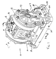
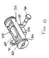
- the instant invention generally designated 10 is shown in Figure 1 in perspective and is comprised of a molded center section 12, two fluid end sections 14 and a valve cover 16.
- center section 12 is molded of polyester resin (PBT) Valox 357 - GE Plastic.
- Cover 16 is fixed via conventional fasteners 18 to center section 12. Also affixed via fasteners 18 to center section 12 are fluid housings 14. The main portion of the pump comprised of center section 12 and fluid housing 14 is affixed to manifold base 20 also via fasteners 18. Manifold base 20 has fluid inlet and outlet passages 22 and 24 respectively located at each end to allow variety in plumbing arrangements.
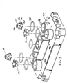
- check valves 26 are each comprised of a central sealing area 26A having in the preferred embodiment four radially and axially extending arms 26B extending therefrom and having a surface 26C which closely positions check valve 26 in check valve passages 28.
- Spring loaded fingers 26D extend from either side of arm 26B and act against the bottom or top of passage 28 to bias check valve 26 into the closed position where it will remain unless fluid pressure against sealing area 26A should press it open.
- the radially extending guide members 26B also act as a stop. The spring fingers 26D compress and the top of the guide arms 26C butts up against the fluid cover 14 on the inlet check and the manifold base 20 on the outlet check. This limits the check valve travel,
- cover 16 has an air inlet 32 which pressurises the area underneath cover 18.
- First and second auxiliary ports 54 and 56 respectively are located in the side of center housing 14 for direct, connection of air from solenoid valves if it is desired to have the pump controlled remotely rather than through the integral air valve.
- the integral ports 54 and 56 make it easy to change a pump from air valve operated to a remotely operated pump by removing the air valve cup and replacing it with an air valve plug.
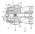
- valve assembly 34 is comprised of a valve carriage 36 which has generally cylindrical end portions 36A having seals 36B thereon, a rectangular central aperture 36C which retains moveable valve block 38.
- Valve block 38 has a lower sealing section 38A and a central section 38B within aperture 36C of carriage 36 which thereby allows valve block 38 to move normal to the plane of Figure 2. This movement occurs due to pushing on block 38 by means of pins 40 which are actuated by diaphragm mounting block 41 in the center of diaphragm 42.
- valve block 38 is formed of 90 Durometer XNBR (Carboxylated Nitrile) with 10% TFE powder to reduce friction.
- air passages M1 and M2 connect to the main air chambers on the inner side of diaphragm assemblies 42 for pressurising the air chambers with compressed air as will be more fully described in the operation of the air valve hereinafter.
- Passages P1 and P2 connect to air chambers 44 and 46 respectively, passages P1 and P2 running as shown in the drawings as straight passages and thence are covered and connected to chambers 44 and 46 by cover 16.
- Valve block 38 is retained in place in valve carriage 36 by boss 16A on cover 16. To disassemble the valve assembly, one merely need remove fasteners 18 from cover 16 and lift cover 16 off whereupon valve block 38 is lifted upwardly thereby allowing valve carriage 36 to be slid out of center housing 16.
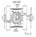
- FIGS 5 to 8 show views of the valve port surface 48 which has five ports therein.
- Central exhaust port E is connected to the exhaust passage 50 while pilot ports P1 and P2 are connected to first and second ends respectively of the pilot valve carriage 36.
- main ports M1 and M2 are connected to first and second diaphragm air chambers respectively.
- the space 52 above the ports referred to is generally filled with compressed air and ports which are not covered by the valve block 38 are pressurised with the compressed air.
- the diaphragms are moving together to the right while the pilot value carriage 36 is in the down position.
- the valve block 38 is moved into the lower right hand position of Figure 8 whereupon compressed air is fed to ports P2 and M2 while ports P1 and M1 are exhausted. This pressurises the lower end of the pilot valve carriage 36 and the pilot valve carriage 36 and the valve block 38 move upwardly to the point where the description started above.
- valve cover 16 which also covers the top of the valve cavity at the same time.
- the inlet threads on the manifold base are such that it allows use of either all American pipe thread (NPT) or British standard pipe thread (BSP).
- NPT American pipe thread
- BSP British standard pipe thread
- This hybrid thread may be formed in plastic parts and is intended to form a pressure tight joint with either plastic or brass male pipe threaded fitting of either type thread.
- the thread is defined as follows: Major diameter 13.16 mm (0.518" ) Pitch 12.30 mm (0.4843") Minor Diameter 11.45 mm (0.4506" ) Angle 1 degree 47 minutes Threads per inch 7.32 (18.6 threads per cm) Effective thread 10.21 mm (0.402"
- the muffler 54 is best seen in Figure 9.
- Exhaust port E leads to cylindrical passage 56 which is divided into first and second portions 56A and 56B by divider 56C.
- the passage is completed by a muffler area 58 in manifold base 20.
- exhaust flows out port E, into first portion 56A and into muffler area 58 whereupon it flows upwardly through second portion 56B and out through muffler outlet 60.
- This arrangement allows substantial muffling at low cost and with little penalty to performance.
Landscapes
- Engineering & Computer Science (AREA)
- Mechanical Engineering (AREA)
- General Engineering & Computer Science (AREA)
- Reciprocating Pumps (AREA)
- Check Valves (AREA)
- Electromagnetic Pumps, Or The Like (AREA)
Claims (2)
- Pompe à air comprimé à mouvement alternatif rectiligne (10) comportant des éléments de pompage (42) qui se déplacent avec un mouvement de va-et-vient le long d'un premier axe, caractérisée en ce qu'elle comprend une soupape d'admission d'air comprenant :un chariot de soupape (36) mobile le long d'un deuxième axe perpendiculaire audit premier axe ;un bloc de soupape (38) mobile dans ledit chariot de soupape le long dudit premier axe ;une surface de soupape (48) comprenant des premier et deuxième orifices principaux (M1, M2) ; des premier et deuxième orifices de commande (P1, P2) et un orifice d'échappement (E) ;un moyen (40) destiné à provoquer le déplacement dudit bloc de soupape pendant le déplacement desdits éléments de pompage ; etun moyen destiné à délivrer de l'air comprimé sur ladite surface de soupape et dans laquelle ledit bloc de soupape se déplace selon une trajectoire rectangulaire globalement plane entre quatre positions, où dans chacune desdites positions, ledit bloc de soupape relie un orifice principal, un orifice de commande et ledit orifice d'échappement.
- Pompe selon la revendication 1, dans laquelle ladite pompe comprend en outre des chambres de commande (44, 46) à chaque extrémité dudit chariot de soupape, chaque dit orifice de commande étant relié à une respective desdites chambres.
Priority Applications (1)
| Application Number | Priority Date | Filing Date | Title |
|---|---|---|---|
| EP99201777A EP0942171B1 (fr) | 1996-04-12 | 1997-04-11 | Pompe à membrane double |
Applications Claiming Priority (4)
| Application Number | Priority Date | Filing Date | Title |
|---|---|---|---|
| US1565096P | 1996-04-12 | 1996-04-12 | |
| US15650 | 1996-04-12 | ||
| US08/837,237 US5860794A (en) | 1997-04-10 | 1997-04-10 | Double diaphragm pump with air valve block moving in a rectangular pattern |
| US837237 | 1997-04-10 |
Related Child Applications (1)
| Application Number | Title | Priority Date | Filing Date |
|---|---|---|---|
| EP99201777A Division EP0942171B1 (fr) | 1996-04-12 | 1997-04-11 | Pompe à membrane double |
Publications (4)
| Publication Number | Publication Date |
|---|---|
| EP0801228A2 EP0801228A2 (fr) | 1997-10-15 |
| EP0801228A3 EP0801228A3 (fr) | 1999-07-21 |
| EP0801228B1 EP0801228B1 (fr) | 2003-07-02 |
| EP0801228B9 true EP0801228B9 (fr) | 2003-10-08 |
Family
ID=26687654
Family Applications (1)
| Application Number | Title | Priority Date | Filing Date |
|---|---|---|---|
| EP97302476A Expired - Lifetime EP0801228B9 (fr) | 1996-04-12 | 1997-04-11 | Pompe à membrane double |
Country Status (6)
| Country | Link |
|---|---|
| EP (1) | EP0801228B9 (fr) |
| JP (2) | JP4004097B2 (fr) |
| KR (2) | KR100491065B1 (fr) |
| CN (2) | CN1165699C (fr) |
| AR (1) | AR006617A1 (fr) |
| DE (2) | DE69723144T2 (fr) |
Families Citing this family (9)
| Publication number | Priority date | Publication date | Assignee | Title |
|---|---|---|---|---|
| GB2463824B (en) * | 2005-05-17 | 2010-06-09 | Thomas Industries Inc | Pump improvements |
| GB2478784B (en) * | 2010-03-19 | 2017-01-25 | Finishing Brands Holdings Inc | Improvements in diaphragm pumps |
| CN105351180A (zh) * | 2015-11-03 | 2016-02-24 | 王庆昌 | 一种双出双进整体式气动隔膜泵 |
| CN106762575A (zh) * | 2016-12-30 | 2017-05-31 | 张家港科康智能科技有限公司 | 一种紧凑性压缩气体隔膜泵 |
| US10823167B2 (en) * | 2019-01-31 | 2020-11-03 | Wilden Pump And Engineering Llc | Pump assembly |
| CN110374846B (zh) * | 2019-07-13 | 2020-12-11 | 新沂市锡沂高新材料产业技术研究院有限公司 | 一种双向气动隔膜泵的交替配气方法 |
| CN110529367B (zh) * | 2019-07-26 | 2020-12-15 | 宁波钱湖石油设备有限公司 | 一种高压往复隔膜泵液力端结构 |
| DE102019132711A1 (de) | 2019-12-02 | 2021-06-02 | Fte Automotive Gmbh | Flüssigkeitspumpe, insbesondere zur Versorgung eines Getriebes oder einer Kupplung im Antriebsstrang eines Kraftfahrzeugs |
| US12135021B2 (en) | 2021-08-17 | 2024-11-05 | Koninklijke Philips N.V. | Suspension system, compressor assembly and portable oxygen concentrator |
Family Cites Families (14)
| Publication number | Priority date | Publication date | Assignee | Title |
|---|---|---|---|---|
| US2748752A (en) * | 1952-04-11 | 1956-06-05 | Baghuis Ludovicus Hendrikus | Automatically reversing valves |
| US4138089A (en) * | 1977-08-09 | 1979-02-06 | The United States Of America As Represented By The Secretary Of The Department Of Health, Education And Welfare | Slide valve |
| JPS5713281A (en) * | 1980-06-28 | 1982-01-23 | Far East Eng Kk | Reciprocating pump |
| US4597403A (en) * | 1983-03-14 | 1986-07-01 | Milburn Jr William W | Nutation valving apparatus and method of operation |
| US4854832A (en) * | 1987-08-17 | 1989-08-08 | The Aro Corporation | Mechanical shift, pneumatic assist pilot valve for diaphragm pump |
| US5062770A (en) * | 1989-08-11 | 1991-11-05 | Systems Chemistry, Inc. | Fluid pumping apparatus and system with leak detection and containment |
| DE4111463A1 (de) * | 1991-04-09 | 1992-10-15 | Festo Kg | Aussengewinde und innengewinde, vorzugsweise zur herstellung fluidischer verbindungen in der pneumatik |
| US5240390A (en) * | 1992-03-27 | 1993-08-31 | Graco Inc. | Air valve actuator for reciprocable machine |
| US5334003A (en) * | 1993-01-25 | 1994-08-02 | The Aro Corporation | Air valving mechanism, in combination with a double diaphragm pump subassembly |
| US5326234A (en) * | 1993-02-17 | 1994-07-05 | Versa-Matic Tool, Inc. | Fluid driven pump |
| US5391060A (en) * | 1993-05-14 | 1995-02-21 | The Aro Corporation | Air operated double diaphragm pump |
| US5368452A (en) * | 1993-07-20 | 1994-11-29 | Graco Inc. | Double diaphragm pump having two-stage air valve actuator |
| CN2174578Y (zh) * | 1993-09-02 | 1994-08-17 | 淄博潜水电泵厂 | 一种双隔膜泵 |
| DE4427981C1 (de) * | 1994-08-08 | 1995-12-07 | Huewel Ralf | Hydraulisch oder pneumatisch betriebene Kolben- und/oder Membran-Pumpe |
-
1997
- 1997-04-11 CN CNB011249986A patent/CN1165699C/zh not_active Expired - Fee Related
- 1997-04-11 JP JP09394897A patent/JP4004097B2/ja not_active Expired - Fee Related
- 1997-04-11 DE DE69723144T patent/DE69723144T2/de not_active Expired - Fee Related
- 1997-04-11 DE DE69723290T patent/DE69723290T2/de not_active Expired - Fee Related
- 1997-04-11 CN CN97111233A patent/CN1081747C/zh not_active Expired - Fee Related
- 1997-04-11 AR ARP970101462A patent/AR006617A1/es unknown
- 1997-04-11 EP EP97302476A patent/EP0801228B9/fr not_active Expired - Lifetime
- 1997-04-12 KR KR1019970013509A patent/KR100491065B1/ko not_active Expired - Fee Related
-
2004
- 2004-06-11 KR KR1020040042785A patent/KR100461707B1/ko not_active Expired - Fee Related
-
2007
- 2007-07-06 JP JP2007178316A patent/JP2007285301A/ja active Pending
Also Published As
| Publication number | Publication date |
|---|---|
| JP4004097B2 (ja) | 2007-11-07 |
| DE69723290T2 (de) | 2004-02-05 |
| EP0801228B1 (fr) | 2003-07-02 |
| KR100461707B1 (ko) | 2004-12-16 |
| CN1165699C (zh) | 2004-09-08 |
| DE69723144D1 (de) | 2003-08-07 |
| EP0801228A2 (fr) | 1997-10-15 |
| CN1374455A (zh) | 2002-10-16 |
| DE69723290D1 (de) | 2003-08-07 |
| CN1174293A (zh) | 1998-02-25 |
| CN1081747C (zh) | 2002-03-27 |
| KR100491065B1 (ko) | 2005-08-12 |
| JPH1030570A (ja) | 1998-02-03 |
| JP2007285301A (ja) | 2007-11-01 |
| EP0801228A3 (fr) | 1999-07-21 |
| AR006617A1 (es) | 1999-09-08 |
| DE69723144T2 (de) | 2004-04-29 |
| KR19980076691A (ko) | 1998-11-16 |
Similar Documents
| Publication | Publication Date | Title |
|---|---|---|
| US5368452A (en) | Double diaphragm pump having two-stage air valve actuator | |
| KR930005874Y1 (ko) | 압축기 | |
| US4819689A (en) | Head-guided poppet valve member and valve assembly | |
| JP3058412B2 (ja) | リニア圧縮機の吐出バルブ装置 | |
| EP0801228B9 (fr) | Pompe à membrane double | |
| US3431865A (en) | Pump with concentric valve means | |
| US5758563A (en) | Fluid driven reciprocating pump | |
| US5009580A (en) | Multiple reciprocating pump | |
| KR101845124B1 (ko) | 펌프 | |
| EP0942171B1 (fr) | Pompe à membrane double | |
| US4480969A (en) | Fluid operated double acting diaphragm pump housing and method | |
| CN1206792A (zh) | 燃料供给泵 | |
| EP1404971B1 (fr) | Pompe a piston plongeur simplex a double effet avec soupapes bidirectionnelles | |
| US4827832A (en) | Valve system for a reciprocating device | |
| KR100253237B1 (ko) | 리니어 압축기의 축방향 밸브장치 | |
| JPH0318039B2 (fr) | ||
| JP2545670Y2 (ja) | 2連往復動ポンプの吐出弁構造 | |
| JPH1182302A (ja) | 往復式圧縮機 | |
| KR20020023517A (ko) | 밀폐형 압축기의 밸브조립체 | |
| CN220522780U (zh) | 一种浮动式柱塞杆机构及柱塞输液泵 | |
| JP3236996U (ja) | 手動式コンプレッサ | |
| JPH0429092Y2 (fr) | ||
| JPS60125787A (ja) | 膜式ポンプ | |
| JP3705616B2 (ja) | エアコンプレッサ | |
| JPH0259305B2 (fr) |
Legal Events
| Date | Code | Title | Description |
|---|---|---|---|
| PUAI | Public reference made under article 153(3) epc to a published international application that has entered the european phase |
Free format text: ORIGINAL CODE: 0009012 |
|
| AK | Designated contracting states |
Kind code of ref document: A2 Designated state(s): DE FR GB IT |
|
| RHK1 | Main classification (correction) |
Ipc: F04B 43/073 |
|
| PUAL | Search report despatched |
Free format text: ORIGINAL CODE: 0009013 |
|
| AK | Designated contracting states |
Kind code of ref document: A3 Designated state(s): DE FR GB IT |
|
| 17P | Request for examination filed |
Effective date: 19991213 |
|
| 17Q | First examination report despatched |
Effective date: 20020805 |
|
| GRAH | Despatch of communication of intention to grant a patent |
Free format text: ORIGINAL CODE: EPIDOS IGRA |
|
| GRAH | Despatch of communication of intention to grant a patent |
Free format text: ORIGINAL CODE: EPIDOS IGRA |
|
| GRAA | (expected) grant |
Free format text: ORIGINAL CODE: 0009210 |
|
| AK | Designated contracting states |
Designated state(s): DE FR GB IT |
|
| REG | Reference to a national code |
Ref country code: GB Ref legal event code: FG4D |
|
| REF | Corresponds to: |
Ref document number: 69723144 Country of ref document: DE Date of ref document: 20030807 Kind code of ref document: P |
|
| ET | Fr: translation filed | ||
| PLBE | No opposition filed within time limit |
Free format text: ORIGINAL CODE: 0009261 |
|
| STAA | Information on the status of an ep patent application or granted ep patent |
Free format text: STATUS: NO OPPOSITION FILED WITHIN TIME LIMIT |
|
| 26N | No opposition filed |
Effective date: 20040405 |
|
| PGFP | Annual fee paid to national office [announced via postgrant information from national office to epo] |
Ref country code: GB Payment date: 20090929 Year of fee payment: 13 |
|
| PGFP | Annual fee paid to national office [announced via postgrant information from national office to epo] |
Ref country code: DE Payment date: 20090929 Year of fee payment: 13 |
|
| PGFP | Annual fee paid to national office [announced via postgrant information from national office to epo] |
Ref country code: IT Payment date: 20091005 Year of fee payment: 13 Ref country code: FR Payment date: 20091019 Year of fee payment: 13 |
|
| GBPC | Gb: european patent ceased through non-payment of renewal fee |
Effective date: 20100411 |
|
| REG | Reference to a national code |
Ref country code: FR Ref legal event code: ST Effective date: 20101230 |
|
| PG25 | Lapsed in a contracting state [announced via postgrant information from national office to epo] |
Ref country code: DE Free format text: LAPSE BECAUSE OF NON-PAYMENT OF DUE FEES Effective date: 20101103 |
|
| PG25 | Lapsed in a contracting state [announced via postgrant information from national office to epo] |
Ref country code: IT Free format text: LAPSE BECAUSE OF NON-PAYMENT OF DUE FEES Effective date: 20100411 Ref country code: GB Free format text: LAPSE BECAUSE OF NON-PAYMENT OF DUE FEES Effective date: 20100411 |
|
| PG25 | Lapsed in a contracting state [announced via postgrant information from national office to epo] |
Ref country code: FR Free format text: LAPSE BECAUSE OF NON-PAYMENT OF DUE FEES Effective date: 20100430 |