EP0801236A1 - Objet muni d'un pas de vis - Google Patents
Objet muni d'un pas de vis Download PDFInfo
- Publication number
- EP0801236A1 EP0801236A1 EP97302259A EP97302259A EP0801236A1 EP 0801236 A1 EP0801236 A1 EP 0801236A1 EP 97302259 A EP97302259 A EP 97302259A EP 97302259 A EP97302259 A EP 97302259A EP 0801236 A1 EP0801236 A1 EP 0801236A1
- Authority
- EP
- European Patent Office
- Prior art keywords
- resilient
- body member
- threaded shaft
- torque
- threaded
- Prior art date
- Legal status (The legal status is an assumption and is not a legal conclusion. Google has not performed a legal analysis and makes no representation as to the accuracy of the status listed.)
- Ceased
Links
- 238000009434 installation Methods 0.000 claims abstract description 19
- 230000002829 reductive effect Effects 0.000 claims abstract description 10
- 230000014759 maintenance of location Effects 0.000 claims description 18
- 238000005520 cutting process Methods 0.000 description 4
- 230000000694 effects Effects 0.000 description 3
- 230000002411 adverse Effects 0.000 description 2
- 230000000994 depressogenic effect Effects 0.000 description 2
- 238000000034 method Methods 0.000 description 2
- 229910000975 Carbon steel Inorganic materials 0.000 description 1
- 238000005452 bending Methods 0.000 description 1
- 230000015572 biosynthetic process Effects 0.000 description 1
- 239000010962 carbon steel Substances 0.000 description 1
- 238000004140 cleaning Methods 0.000 description 1
- 239000011248 coating agent Substances 0.000 description 1
- 238000000576 coating method Methods 0.000 description 1
- 230000003292 diminished effect Effects 0.000 description 1
- 238000010438 heat treatment Methods 0.000 description 1
- 230000000670 limiting effect Effects 0.000 description 1
- 238000012423 maintenance Methods 0.000 description 1
- 238000004519 manufacturing process Methods 0.000 description 1
- 239000000463 material Substances 0.000 description 1
- 239000007769 metal material Substances 0.000 description 1
- 230000036961 partial effect Effects 0.000 description 1
- 238000007747 plating Methods 0.000 description 1
- 230000000717 retained effect Effects 0.000 description 1
- 239000010935 stainless steel Substances 0.000 description 1
- 229910001220 stainless steel Inorganic materials 0.000 description 1
Images
Classifications
-
- F—MECHANICAL ENGINEERING; LIGHTING; HEATING; WEAPONS; BLASTING
- F16—ENGINEERING ELEMENTS AND UNITS; GENERAL MEASURES FOR PRODUCING AND MAINTAINING EFFECTIVE FUNCTIONING OF MACHINES OR INSTALLATIONS; THERMAL INSULATION IN GENERAL
- F16B—DEVICES FOR FASTENING OR SECURING CONSTRUCTIONAL ELEMENTS OR MACHINE PARTS TOGETHER, e.g. NAILS, BOLTS, CIRCLIPS, CLAMPS, CLIPS OR WEDGES; JOINTS OR JOINTING
- F16B39/00—Locking of screws, bolts or nuts
- F16B39/22—Locking of screws, bolts or nuts in which the locking takes place during screwing down or tightening
- F16B39/28—Locking of screws, bolts or nuts in which the locking takes place during screwing down or tightening by special members on, or shape of, the nut or bolt
- F16B39/284—Locking by means of elastic deformation
- F16B39/286—Locking by means of elastic deformation caused by saw cuts
Definitions
- the invention relates generally to an article engagable and retainable about a threaded shaft, and in a specific embodiment to a low profile, self locking unitary nut having a relatively consistent torque performance with a reduced statistical spread over several repeated cycles of nut installation and nut removal about the threaded shaft.
- Lock nuts with a threaded bore engagable about a threaded shaft have many configurations and applications. There exists for example a variety of lock nuts having gaps arranged transversely to the bore axis or gaps arranged radially to the bore axis and proximate one end portion of the nut. The gaps are narrowed by deformation of the nut to misalign the threads in an effort to provide means for retaining the nut in tight engagement about the shaft. Nut retention performance however is often diminished substantially upon removal of the nut from the shaft resulting from a tendency of the gap or gaps to widen as the nut is thread about the shaft during installation and removal.
- US-A-815,541 discusses a nut lock having opposing U-shape members disposed about a threaded bore wherein the U-shape members are formed by a combination of slots arranged transversely and radially to the bore axis. A median portion of each U-shape member is connected to the nut by a corresponding neck, and the end portions of the U-shape members are inwardly bent toward the bore axis to provide tight engagement with the shaft.
- This nut however lacks optimum retention performance, has low retention performance after removal from the shaft, and has a relatively inconsistent torque performance with a large statistical spread, which often fails to comply with industry established torque specifications.
- US-A-2,213,353 discusses a lock nut having opposing U-shape members formed in a cylindrical extension of the nut.
- the trailing end portion of each U-shape member is downwardly bent, and one or more end portions are inwardly bent toward the bore axis for nut retention.
- this teaches away from downwardly bending the leading end portion of each U-shaped member to prevent cross threading during installation.
- the cylindrical extension disposed on this nut adversely increases the profile of the nut thereby limiting its use in applications that require a low profile.
- This nut also lacks optimum retention performance, has low retention performance after removal from the shaft, and has a relatively inconsistent torque performance with a large statistical spread, which often fails to comply with industry established torque specifications.
- an article engagable and retainable about a threaded shaft comprises a body member having a threaded bore with a bore axis for receiving the threaded shaft; a plurality of resilient posts extending along the body member, each resilient post inclined inwardly toward the bore axis to provide a prevailing torque on a threaded shaft disposed in the threaded bore; a pair of resilient arms with end portions extending from each resilient post, each resilient arm of the pair extending from a substantially opposing side of the corresponding resilient post, each resilient arm inclined toward the body member to provide a prevailing torque on a threaded shaft disposed in the threaded bore, wherein the resilient posts and resilient arms contribute to retention of the body member about the threaded shaft.
- the present invention provides a threaded article that is economical, reusable and provides improved torque performance. It also has a reduced first on torque and has a relatively consistent torque performance with reduced statistical spread over several nut installation and removal cycles. Preferably the article has an improved torque performance that meets an established torque specification.
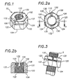
- Figure 1 to 3 illustrate an article 10, which in the exemplary embodiment is a self locking nut, generally comprising a body member 100 with a threaded bore 110 having a bore axis for receiving a threaded shaft S of a bolt or other member known in the art wherein the nut is engagable and retainable about the threaded shaft.
- a self locking nut generally comprising a body member 100 with a threaded bore 110 having a bore axis for receiving a threaded shaft S of a bolt or other member known in the art wherein the nut is engagable and retainable about the threaded shaft.
- the exemplary embodiment of the invention is discussed in the context of self locking nuts with tool engagable outer surfaces, the objects, features and advantages of the invention are likewise applicable to a general class of rotatable or fixed body members like tappets, pipes and flanges having a threaded bore portion for receiving a threaded shaft portion.
- the exemplary embodiment also includes a first end 102, an opposing second end 104 and a side portion 106, which may be configured with a tool engagable side surface having a square, hexagonal or other useful shape.
- Figure 2b includes a partial sectional view of an alternative body member with a modified side portion having a quasi-conical shape 108 tapered or bevelled toward the first end 102.
- a plurality of resilient posts 120 extend along the body member 100.
- Figure 2b shows each resilient post inclined inwardly toward the bore axis to provide a prevailing torque on a threaded shaft disposed in the threaded bore.
- the plurality of resilient posts contribute to retention of the body member about the threaded shaft and prevent casual removal therefrom, which may result from vibration and thermal effects among other sources.
- the resilient posts 120 may be defined by transverse gaps 122 formed or disposed in respective side portions of the body member.
- the exemplary embodiment includes two transverse gaps 122 on substantially opposing sides of the body member to define two resilient posts 120.
- Each transverse gap is arranged substantially transverse to the bore axis. In the exemplary embodiment, the transverse gaps are transverse to the bore axis.
- the transverse gaps are inclined slightly relative to the bore axis at least parallel with the bore threads.
- the transverse gaps of the exemplary embodiment are located toward the first end 102 and extend through the side surface 106 or the tapered surface 108.
- the transverse gaps may alternatively be located anywhere along the side portion of the body member between the opposing ends 102 and 104.
- resilient posts 120 are defined by transverse gaps 122 formable by a cutting operation, which generally occurs after threading the bore wherein portions of the resilient posts 120 also have a threaded surface.
- the resilient posts 120 may be formed by other operations and processes either before or after threading the bore.
- Figure. 2a illustrates a first transverse gap having a linear or straight edge 124 formable with a straight edge cutting tool.
- Figure. 2 also illustrates a second transverse gap having an arcuate edge 126 alternatively formable with a curved edge cutting tool like a rotary disk.
- a pair of resilient arms 130 extend from each resilient post 120 wherein each arm extends from a substantially opposing side of the corresponding resilient post.
- Figure 2b shows each resilient arm 130 inclined downwardly toward the body member 100 to provide a prevailing torque on a threaded shaft disposed in the threaded bore.
- the resilient arms 130 also contribute to retention of the body member about the threaded shaft, and prevent casual removal therefrom as discussed above.
- the resilient arms 130 may be defined by radial gaps 132 formed or disposed in respective side portions of the body member and intersecting corresponding transverse gaps 122. In the exemplary embodiment, two radial gaps 132 extending through the first end 102 intersect corresponding transverse gaps 122 to define the pair of resilient arms 130 on the two resilient posts 120.
- Additional radial gaps may be used to define additional resilient arms in alternative embodiments that include additional resilient posts.
- Each radial gap in the exemplary embodiment is arranged substantially radially to the bore axis, but in general the radial gap is oriented at any angle so long as the radial gap intersects the transverse gap to define a resilient arm that may be staked or depressed downwardly.
- the radial gaps are formable by a cutting operation, which generally occurs after threading of the bore wherein portions of the resilient arms 130 also have a threaded surface.
- the resilient arms 130 may be formed by other operations and processes either before or after threading the bore.
- end portions of the resilient arms 130 are staked or depressed downwardly toward the body member and the plurality of resilient posts 120 are inclined inwardly toward the bore axis.
- the deformed configuration of the resilient posts and resilient arms results in deformation of the bore threads and narrowing of at least a portion of the bore to provide a spring effect on a threaded shaft disposed in the bore, which effectively retains the body member about the shaft with a prevailing torque that resists loosening rotation of the body member relative to the shaft.
- the transverse and radial gaps are dimensioned to permit configuration of the resilient posts and resilient arms as discussed above.
- the self locking member 10 may alternatively be further processed by application of a coating or plating and heat treatment after formation and configuration of the resilient arms and resilient posts as discussed above.
- the self locking body member preferably is a unitary member formed of a metal material that provides sufficient stress and tensile performance and at the same time is sufficiently resilient for optimum retention performance.
- the body member may for example be comprised of a carbon steel, or stainless steel or other material.
- a threaded shaft S is disposed initially in the threaded bore through the second end 104 of the body member wherein the threads of the shaft are received without significant resistance.
- the shaft begins to engage the deformed or misaligned threads and meet spring resistance from the inwardly inclined resilient posts and staked resilient arms.
- Figure. 3 illustrates the threaded shaft S urging the resilient posts 120 and resilient arms 130 toward the pre-deformed configuration wherein the shaft is subject to the prevailing torque provided by the downwardly staked resilient arms and the inwardly inclined resilient posts.
- the resilient posts and resilient arms also result in a reduced first installation torque and provide relatively consistent torque performance with reduced statistical spread over several installation and removal cycles.
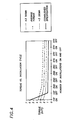
- Figure 4 is a graphical illustration of Torque performance versus Installation Cycle of a prevailing torque nut according to the present invention.
- the solid line is an Established Specification which is satisfied when the "1st On” torque is below the solid line and when the "1st. Off” torque through the "5th Off” torque are above the solid line.
- the prevailing torque nut of the present invention has a relatively low “1st On” torque and relatively consistent retention performance with reduced statistical spread over several nut installation and removal cycles.
- Figure 4 shows that the average torque and corresponding statistical spread between "+3Sigma” and “-3Sigma” decrease at nearly constant rates characterized by a moderate downward slope that is within the Established Specification between the "lst On” and the "5th Off".
- the relatively flat slope indicates that the torque performance remains substantially constant over several nut installation and removal cycles without the substantial decrease in retention performance characteristic of prior art nuts.
- the statistical spread of the present invention is also reduced relative to the statistical spread of prior art lock nuts.
Landscapes
- Engineering & Computer Science (AREA)
- General Engineering & Computer Science (AREA)
- Mechanical Engineering (AREA)
- Dowels (AREA)
- Bolts, Nuts, And Washers (AREA)
Applications Claiming Priority (2)
| Application Number | Priority Date | Filing Date | Title |
|---|---|---|---|
| US08/628,923 US5662443A (en) | 1996-04-08 | 1996-04-08 | Prevailing torque nut |
| US628923 | 1996-04-08 |
Publications (1)
| Publication Number | Publication Date |
|---|---|
| EP0801236A1 true EP0801236A1 (fr) | 1997-10-15 |
Family
ID=24520869
Family Applications (1)
| Application Number | Title | Priority Date | Filing Date |
|---|---|---|---|
| EP97302259A Ceased EP0801236A1 (fr) | 1996-04-08 | 1997-04-02 | Objet muni d'un pas de vis |
Country Status (3)
| Country | Link |
|---|---|
| US (1) | US5662443A (fr) |
| EP (1) | EP0801236A1 (fr) |
| CA (1) | CA2199205C (fr) |
Cited By (2)
| Publication number | Priority date | Publication date | Assignee | Title |
|---|---|---|---|---|
| US9145923B2 (en) | 2013-07-03 | 2015-09-29 | General Electric Company | Load coupling for adjusting torsional natural frequency of a power train |
| US9518610B2 (en) | 2013-05-28 | 2016-12-13 | General Electric Company | Load coupling and method for adjusting torsional natural frequency of power train |
Families Citing this family (19)
| Publication number | Priority date | Publication date | Assignee | Title |
|---|---|---|---|---|
| US6224112B1 (en) | 1997-07-18 | 2001-05-01 | Weatherford/Lamb, Inc. | Casing slip joint |
| US5915902A (en) * | 1997-09-19 | 1999-06-29 | Illinois Tool Works Inc. | Undeformed lock nut with slot |
| US6090146A (en) * | 1999-06-16 | 2000-07-18 | Bristol-Myers Squibb Company | Fastener for a modular implant |
| US6095734A (en) * | 1999-09-21 | 2000-08-01 | Transtechnology Corp. | Pushnut |
| JP3772265B2 (ja) * | 2000-05-17 | 2006-05-10 | 株式会社シマノ | 釣り用塗装部品 |
| SE516862C2 (sv) * | 2000-07-14 | 2002-03-12 | Allgon Ab | Avstämningsskruvanordning samt metod och resonator |
| KR20050111219A (ko) * | 2004-05-21 | 2005-11-24 | 가부시키가이샤 에코 월드 | 이완 방지 너트와 그 제조방법 |
| US7455695B2 (en) * | 2004-06-28 | 2008-11-25 | Depuy Products, Inc. | Modular prosthesis and locking nut therefor |
| TW200801354A (en) * | 2006-06-20 | 2008-01-01 | Asustek Comp Inc | A nut having a cutting gap and fixing structure |
| US20090202317A1 (en) * | 2006-06-20 | 2009-08-13 | Safilo Societa Azionaria Fabbrica Italianna Lavorazione Occhiali S.P.A | Self-locking nut for securing components for spectacles and method of manufacture thereof |
| US20090064480A1 (en) * | 2007-09-11 | 2009-03-12 | Hiroaki Migita | Method of a fastening a bolt and a nut and their fastening structure |
| CN101660561B (zh) * | 2008-08-28 | 2011-01-26 | 鸿富锦精密工业(深圳)有限公司 | 螺母结构及其制造方法 |
| KR101172868B1 (ko) * | 2010-05-24 | 2012-08-09 | 이용국 | 록크 너트 및 이를 구비하는 체결 유닛 |
| US9194421B2 (en) * | 2013-03-24 | 2015-11-24 | Arnold Permanent Nut, LLC | One-piece self-locking nut |
| JP6417059B1 (ja) * | 2017-05-29 | 2018-10-31 | 宝輝 山下 | ナットおよび締結方法 |
| US11213329B2 (en) * | 2020-02-28 | 2022-01-04 | DePuy Synthes Products, Inc. | Bone fracture fixation clamp |
| CN113898656A (zh) * | 2021-10-15 | 2022-01-07 | 中车大同电力机车有限公司 | 防松连接结构及机车 |
| CN115289125B (zh) * | 2022-08-30 | 2023-05-26 | 拉萨誉致信科技有限公司 | 一种防松动螺母 |
| US20240229990A9 (en) * | 2022-10-25 | 2024-07-11 | Petróleo Brasileiro S.A. - Petrobras | Nut guide |
Citations (6)
| Publication number | Priority date | Publication date | Assignee | Title |
|---|---|---|---|---|
| US2213353A (en) * | 1938-08-15 | 1940-09-03 | Guest Keen & Nettlefolds Ltd | Nut |
| US2381111A (en) * | 1943-05-25 | 1945-08-07 | Edward F Chandler | Self-locking nut |
| CH247303A (fr) * | 1945-06-29 | 1947-02-28 | Affolter Auguste | Ecrou de sûreté et procédé pour sa fabrication. |
| DE1802372A1 (de) * | 1967-10-31 | 1969-05-14 | Marcel Deraeve | Mutter mit Losdrehsicherung |
| EP0101783A1 (fr) * | 1982-08-31 | 1984-03-07 | Iwata Bolt Kogyo Kabushiki Kaisha | Jeu d'écrou ne pouvant se desserrer et contre-écrou |
| EP0460335A1 (fr) * | 1989-03-30 | 1991-12-11 | Rexnord Holdings Inc. | Ecrou de blocage |
Family Cites Families (12)
| Publication number | Priority date | Publication date | Assignee | Title |
|---|---|---|---|---|
| US815541A (en) * | 1905-04-17 | 1906-03-20 | Charles E Greenwald | Nut-lock. |
| US961063A (en) * | 1909-10-26 | 1910-06-07 | James C Austin | Nut-lock. |
| US2142820A (en) * | 1937-05-22 | 1939-01-03 | Illinois Tool Works | Self-gripping device |
| US2221961A (en) * | 1938-07-23 | 1940-11-19 | James R Allen | Bolt locking means |
| FR850193A (fr) * | 1939-02-11 | 1939-12-09 | écrou indesserrable | |
| US2487219A (en) * | 1944-03-29 | 1949-11-08 | John W Butler | Self-locking nut |
| FR929985A (fr) * | 1945-06-29 | 1948-01-13 | écrou de sûreté et son procédé de fabrication | |
| FR940752A (fr) * | 1947-02-05 | 1948-12-22 | écrou avec frein élastique | |
| BE549983A (fr) * | 1952-10-31 | |||
| FR1371833A (fr) * | 1963-06-14 | 1964-09-11 | Nouveautes Mecaniques Electr N | écrou indesserrable |
| US3702628A (en) * | 1970-11-27 | 1972-11-14 | Tridair Industries | Lock nut member |
| US5499893A (en) * | 1993-12-29 | 1996-03-19 | Illinois Tool Works Inc. | Flexible lock nut and method of manufacturing |
-
1996
- 1996-04-08 US US08/628,923 patent/US5662443A/en not_active Expired - Fee Related
-
1997
- 1997-03-05 CA CA002199205A patent/CA2199205C/fr not_active Expired - Fee Related
- 1997-04-02 EP EP97302259A patent/EP0801236A1/fr not_active Ceased
Patent Citations (6)
| Publication number | Priority date | Publication date | Assignee | Title |
|---|---|---|---|---|
| US2213353A (en) * | 1938-08-15 | 1940-09-03 | Guest Keen & Nettlefolds Ltd | Nut |
| US2381111A (en) * | 1943-05-25 | 1945-08-07 | Edward F Chandler | Self-locking nut |
| CH247303A (fr) * | 1945-06-29 | 1947-02-28 | Affolter Auguste | Ecrou de sûreté et procédé pour sa fabrication. |
| DE1802372A1 (de) * | 1967-10-31 | 1969-05-14 | Marcel Deraeve | Mutter mit Losdrehsicherung |
| EP0101783A1 (fr) * | 1982-08-31 | 1984-03-07 | Iwata Bolt Kogyo Kabushiki Kaisha | Jeu d'écrou ne pouvant se desserrer et contre-écrou |
| EP0460335A1 (fr) * | 1989-03-30 | 1991-12-11 | Rexnord Holdings Inc. | Ecrou de blocage |
Cited By (2)
| Publication number | Priority date | Publication date | Assignee | Title |
|---|---|---|---|---|
| US9518610B2 (en) | 2013-05-28 | 2016-12-13 | General Electric Company | Load coupling and method for adjusting torsional natural frequency of power train |
| US9145923B2 (en) | 2013-07-03 | 2015-09-29 | General Electric Company | Load coupling for adjusting torsional natural frequency of a power train |
Also Published As
| Publication number | Publication date |
|---|---|
| CA2199205C (fr) | 2002-02-19 |
| US5662443A (en) | 1997-09-02 |
| MX9702510A (es) | 1997-10-31 |
| CA2199205A1 (fr) | 1997-10-08 |
Similar Documents
| Publication | Publication Date | Title |
|---|---|---|
| EP0801236A1 (fr) | Objet muni d'un pas de vis | |
| US6318940B1 (en) | Fastener for self-locking securement within a panel opening | |
| US6190101B1 (en) | Low tolerance threaded fastener | |
| AU708510B2 (en) | Underformed lock nut with slot | |
| US3825051A (en) | Self-locking bolt | |
| US6688988B2 (en) | Looking thread cold forming tool | |
| US6132153A (en) | Zero on prevailing torque nut | |
| US3252495A (en) | Bolt with a knurled barrel-shaped shank | |
| US4341497A (en) | Prevailing torque bolt | |
| EP0024528A2 (fr) | Forme taraudeuse | |
| US5636956A (en) | Fastener and screw means therefor | |
| EP1182366A1 (fr) | Eléments avec filetage | |
| EP0541803A1 (fr) | Vis et machoire a filet | |
| US5580199A (en) | Fastening screw | |
| US4493597A (en) | Nut lock assembly | |
| JPH04244612A (ja) | 自動係止ファスナ | |
| US6881019B2 (en) | Method and structure for locknut with substantially rigid locking member | |
| US3118479A (en) | Self locking fastener having deformed threaded portion | |
| CA2199343C (fr) | Methode pour mettre a dimensions un ecrou de blocage | |
| EP0746697A1 (fr) | Dispositif de fixation a verrouillage visse | |
| US4682924A (en) | Self-locking nut device and method | |
| MXPA97002510A (es) | Tuerca comun de par torsor | |
| JPH10141349A (ja) | 緩み止めナット、並びに、その製造方法 | |
| CA1119440A (fr) | Organe d'assemblage a contre-ecrou | |
| AU750256B2 (en) | Screwspike |
Legal Events
| Date | Code | Title | Description |
|---|---|---|---|
| PUAI | Public reference made under article 153(3) epc to a published international application that has entered the european phase |
Free format text: ORIGINAL CODE: 0009012 |
|
| AK | Designated contracting states |
Kind code of ref document: A1 Designated state(s): DE ES FR GB IT |
|
| 17P | Request for examination filed |
Effective date: 19980403 |
|
| 17Q | First examination report despatched |
Effective date: 19980602 |
|
| GRAG | Despatch of communication of intention to grant |
Free format text: ORIGINAL CODE: EPIDOS AGRA |
|
| STAA | Information on the status of an ep patent application or granted ep patent |
Free format text: STATUS: THE APPLICATION HAS BEEN REFUSED |
|
| 18R | Application refused |
Effective date: 19991113 |