EP0801242B1 - Accouplement hydrodynamique - Google Patents
Accouplement hydrodynamique Download PDFInfo
- Publication number
- EP0801242B1 EP0801242B1 EP97103677A EP97103677A EP0801242B1 EP 0801242 B1 EP0801242 B1 EP 0801242B1 EP 97103677 A EP97103677 A EP 97103677A EP 97103677 A EP97103677 A EP 97103677A EP 0801242 B1 EP0801242 B1 EP 0801242B1
- Authority
- EP
- European Patent Office
- Prior art keywords
- coupling according
- turbine wheel
- coupling
- circular
- chamber
- Prior art date
- Legal status (The legal status is an assumption and is not a legal conclusion. Google has not performed a legal analysis and makes no representation as to the accuracy of the status listed.)
- Expired - Lifetime
Links
- 230000008878 coupling Effects 0.000 title claims description 24
- 238000010168 coupling process Methods 0.000 title claims description 24
- 238000005859 coupling reaction Methods 0.000 title claims description 24
- 238000003860 storage Methods 0.000 description 24
- 230000005540 biological transmission Effects 0.000 description 3
- TVEXGJYMHHTVKP-UHFFFAOYSA-N 6-oxabicyclo[3.2.1]oct-3-en-7-one Chemical compound C1C2C(=O)OC1C=CC2 TVEXGJYMHHTVKP-UHFFFAOYSA-N 0.000 description 1
- 238000010276 construction Methods 0.000 description 1
- 230000006735 deficit Effects 0.000 description 1
- 230000003111 delayed effect Effects 0.000 description 1
- 230000000694 effects Effects 0.000 description 1
- 238000004519 manufacturing process Methods 0.000 description 1
- 238000000034 method Methods 0.000 description 1
- 230000002093 peripheral effect Effects 0.000 description 1
- 238000010926 purge Methods 0.000 description 1
Images


Classifications
-
- F—MECHANICAL ENGINEERING; LIGHTING; HEATING; WEAPONS; BLASTING
- F16—ENGINEERING ELEMENTS AND UNITS; GENERAL MEASURES FOR PRODUCING AND MAINTAINING EFFECTIVE FUNCTIONING OF MACHINES OR INSTALLATIONS; THERMAL INSULATION IN GENERAL
- F16D—COUPLINGS FOR TRANSMITTING ROTATION; CLUTCHES; BRAKES
- F16D33/00—Rotary fluid couplings or clutches of the hydrokinetic type
- F16D33/06—Rotary fluid couplings or clutches of the hydrokinetic type controlled by changing the amount of liquid in the working circuit
- F16D33/08—Rotary fluid couplings or clutches of the hydrokinetic type controlled by changing the amount of liquid in the working circuit by devices incorporated in the fluid coupling, with or without remote control
Definitions
- the invention relates to a hydrodynamic clutch with automatic Torque limitation.
- Hydrodynamic couplings have the advantage of an elastic one Work behavior and a smooth, relatively shock-free transmission of a Torque, for example from a motor to a conveyor belt.
- a Torque for example from a motor to a conveyor belt.
- limit or lower transmissible torque This will the engine is spared even more when starting off.
- DE-AS 1 218 118 describes a hydrodynamic coupling, which also has an automatic torque limit.
- a storage space provided with the working space via a in the turbine wheel intended passage is connected.
- DE-U 84 14 929 describes a coupling with a storage space through a throttle disc is limited.
- the throttle disc reaches into the work area a, so that a constant impairment of the flow in the work area he follows.
- US 3 173 260 describes a hydrodynamic clutch in which one Disc arranged in the middle plane between the pump wheel and turbine wheel which extends in the radial direction.
- On the pump side is a Storage space provided. This is opposed to that by a throttle disc Turbine wheel limited.
- the blades of the turbine wheel extend in the area of the throttle plate, and the throttle plate extends to Blading the turbine wheel. Therefore, the current in the Working space constantly affected by the throttle disc, which is for operation the clutch is disadvantageous.
- a generic hydrodynamic coupling with an automatic Torque limitation is known from the document FR-A-2 676 521.
- This discloses a hydrodynamic clutch with a pump wheel a turbine wheel, which together form a toroidal working space form, with the impeller a shell is rotatably connected, the engages around the turbine wheel and forms an annular gap with it, which is radial communicated outside with the work area.
- the shell carries on her radially inner end an annular chamber concentric to the coupling axis, the encloses a storage space.
- the openings between the storage space and the annular gap viewed in the radial direction are at a height which is in the The area of the lower edge of the toroidal work area is higher or higher.
- On The main disadvantage of such an embodiment is that especially with a small filling, the storage space is no longer completely filled can or the emptying not quickly to the desired extent can be done. This is disadvantageous for the starting process.
- the invention has for its object a hydrodynamic coupling to create that has a storage space, and with which an even gentler Starting is possible.
- the coupling should be simple in construction and inexpensive to be in production.
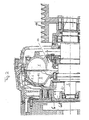
- Figure 1 shows a hydrodynamic coupling in an overall view in a cross section perpendicular to the axis.
- Figure 2 shows a hydrodynamic clutch again in one perpendicular cut; the parts essential to the invention are better here recognizable.
- Fig. 3 shows a hydrodynamic clutch in a view similar to that 2.
- a storage space 6.1 is provided which is separated by a Cover disc 6.2 is limited.
- a conductive connection between storage space 6.1 and the working space of the clutch is in the form of an axial extending annular gap 6.7 provided.
- the Coupling housing 4 is with housing 7 one not shown here Screwed motor. It also carries a by means of a plug connection Flywheel 8. Flywheel 8 has a coupling flange 9 screwed. This is via driver 10 with the shell 5 and thus with the impeller 1 rotatably connected.
- the turbine wheel is rotatably connected to the shaft 3 and carries on it right end a pulley 11.
- Torque is introduced into the flywheel 8 by the engine, from there to the coupling flange 9, then via the driver 10 to the shell 5 and thus to clutch wheel 1 Torque transmission hydrodynamically via that in the work area located oil to the turbine wheel 2, from there to the shaft 3 and on to Pulley 11.
- Impeller 1 and Turbine wheel 2 have blades which are not described in more detail here.
- the bladed space is the working space of the coupling.
- annular gap 12 educated. This has a relatively small cross section. He is standing with one Storage space 6.1 in a conductive connection from the annular chamber 6 is enclosed.
- the storage space 6.1 is by an annular cover plate 6.2 limited. Between the inner circumference of the cover 6.2 and the An annular gap 6.3 is provided for shaft 3.
- On the outer circumference of the Throttle disc 6.2 holes 6.4 are provided.
- Another storage space 13 can be seen radially between pump wheel 1 and the shaft 3. This auxiliary storage space may be present, but it is not mandatory.
- the Coupling according to the invention the advantage that it is only a small Takes up space.
Landscapes
- Engineering & Computer Science (AREA)
- General Engineering & Computer Science (AREA)
- Mechanical Engineering (AREA)
- Hydraulic Clutches, Magnetic Clutches, Fluid Clutches, And Fluid Joints (AREA)
- Mechanical Operated Clutches (AREA)
Claims (7)
- Accouplement hydrodynamique à limitation automatique du couple, présentant les caractéristiques suivantes:1.1 une roue de pompe (1) et une roue de turbine (2) définissent ensemble une chambre de travail de forme toroïdale,1.2 un bol (5) est solidaire en rotation de la roue de pompe (1), lequel bol entoure la roue de turbine (2) et définit avec celle-ci un premier espace annulaire (12) qui, radialement à l'extérieur, communique avec la chambre de travail;1.3 le bol (5) porte, à son extrémité située radialement à l'intérieur, une chambre annulaire (6) concentrique avec l'axe de l'accouplement qui entoure un volume de retenue (6.1)1.4 le volume de retenue (6.1) communique avec le premier espace annulaire (12) par des ouvertures (6.3, 6.4),
caractérisé par les caractéristiques suivantes1.5 le volume de retenue (6.1) est limité par une plaque de fermeture (6.2) qui présente au moins un deuxième espace annulaire (6.3)1.6 le deuxième espace annulaire (6.3) est situé entre l'arbre (3) de la roue de turbine (2) et la plaque de fermeture (6.2). - Accouplement selon la revendication 1, caractérisé en ce que le volume de retenue (6.1) communique avec l'espace annulaire (12) par des ouvertures radialement extérieures (6.4) et radialement intérieures (6.3).
- Accouplement selon la revendication 1 ou 2, caractérisé en ce qu'il est prévu un volume de retenue auxiliaire (13) qui est situé à l'intérieur de la chambre de travail et est entouré par la roue de pompe.
- Accouplement selon une des revendications 1 à 3, caractérisé en ce que le nombre des ouvertures (6.4) est d'au moins quatre.
- Accouplement selon une des revendications 1 à 4, caractérisé en ce que la plaque de fermeture (6.2) est fixée au moyen d'un anneau de retenue.
- Accouplement selon une des revendications 1 à 5, caractérisé en ce que les ouvertures (6.4) sont situées dans la zone radialement extérieure de la plaque de fermeture (6.2).
- Accouplement selon une des revendications 1 à 6, caractérisé en ce que le volume de retenue (6.1) communique avec l'espace annulaire (12) entre la roue de turbine (2) et le bol (5) seulement par un espace supplémentaire qui est ménagé entre la chambre annulaire (6) et l'arbre de turbine et dont la dimension en largeur est adaptée.
Applications Claiming Priority (2)
| Application Number | Priority Date | Filing Date | Title |
|---|---|---|---|
| DE19614591A DE19614591A1 (de) | 1996-04-12 | 1996-04-12 | Hydrodynamische Kupplung |
| DE19614591 | 1996-04-12 |
Publications (2)
| Publication Number | Publication Date |
|---|---|
| EP0801242A1 EP0801242A1 (fr) | 1997-10-15 |
| EP0801242B1 true EP0801242B1 (fr) | 2001-06-06 |
Family
ID=7791153
Family Applications (1)
| Application Number | Title | Priority Date | Filing Date |
|---|---|---|---|
| EP97103677A Expired - Lifetime EP0801242B1 (fr) | 1996-04-12 | 1997-03-06 | Accouplement hydrodynamique |
Country Status (2)
| Country | Link |
|---|---|
| EP (1) | EP0801242B1 (fr) |
| DE (2) | DE19614591A1 (fr) |
Families Citing this family (1)
| Publication number | Priority date | Publication date | Assignee | Title |
|---|---|---|---|---|
| DE19614591A1 (de) * | 1996-04-12 | 1996-09-26 | Voith Turbo Kg | Hydrodynamische Kupplung |
Family Cites Families (11)
| Publication number | Priority date | Publication date | Assignee | Title |
|---|---|---|---|---|
| DE7521295U (de) * | 1976-03-04 | Kloeckner-Werke Ag, 4100 Duisburg | Hydrodynamische Kupplung | |
| DE432316C (de) * | 1924-11-01 | 1926-08-03 | Stettin Act Ges | Hydraulische Kupplung |
| AT229725B (de) * | 1961-07-22 | 1963-10-10 | Voith Getriebe Kg | Kernringlose Strömungskupplung, insbesondere für Kraftfahrzeuge |
| FR91599E (fr) * | 1967-01-13 | 1968-07-05 | Ferodo Sa | Perfectionnements apportés aux coupleurs hydrauliques |
| DE6807272U (de) * | 1968-11-16 | 1969-03-06 | Westfalia Separator Ag | Fluessigkeitskupplung fuer separatoren |
| GB1398788A (en) * | 1972-08-02 | 1975-06-25 | Schiffelers T G M | Kinetic fluid couplings |
| DE8414929U1 (de) * | 1984-05-16 | 1984-08-09 | Voith-Turbo Gmbh & Co Kg, 7180 Crailsheim | Hydrodynamische kupplung |
| FR2673987B1 (fr) * | 1991-03-13 | 1995-09-22 | Sime Ind | Coupleur hydrocinetique a remplissage fixe et chambres de retardement principale et auxiliaire. |
| FR2676521B1 (fr) * | 1991-05-15 | 1997-04-04 | Sime Ind | Coupleur hydrocinetique a remplissage fixe et chambre de retardement interne au circuit de travail. |
| DE4311350C2 (de) * | 1993-04-06 | 1996-02-08 | Voith Turbo Kg | Hydrodynamische Kupplung |
| DE19614591A1 (de) * | 1996-04-12 | 1996-09-26 | Voith Turbo Kg | Hydrodynamische Kupplung |
-
1996
- 1996-04-12 DE DE19614591A patent/DE19614591A1/de not_active Withdrawn
-
1997
- 1997-03-06 EP EP97103677A patent/EP0801242B1/fr not_active Expired - Lifetime
- 1997-03-06 DE DE59703710T patent/DE59703710D1/de not_active Expired - Lifetime
Also Published As
| Publication number | Publication date |
|---|---|
| DE59703710D1 (de) | 2001-07-12 |
| EP0801242A1 (fr) | 1997-10-15 |
| DE19614591A1 (de) | 1996-09-26 |
Similar Documents
| Publication | Publication Date | Title |
|---|---|---|
| DE4316289C2 (de) | Schalt- und Übertragungskupplungsvorrichtung für einen hydrodynamischen Drehmomentwandler | |
| DE2809847C2 (de) | Thermostatgesteuerte Kupplung | |
| DE3743976C3 (de) | Vorrichtung zur Drehmomentübertragung | |
| DE69031689T2 (de) | Stufenlos verstellbares Getriebe | |
| DE3800045C2 (de) | Kraftübertragungseinrichtung für ein vierrad-getriebenes Fahrzeug | |
| DE10154286B4 (de) | Drehmomentwandler | |
| DE3721560C2 (fr) | ||
| DE19836775B4 (de) | Drehmomentwandler | |
| DE19519227A1 (de) | Getriebebaugruppe für Zugmaschinen | |
| DE69014904T2 (de) | Rotationskontrollgeräte. | |
| EP0801243B1 (fr) | Accouplement hydrodynamique | |
| DE3841237C2 (de) | Flügelzellenpumpen-Getriebekupplung für vierradgetriebene Fahrzeuge | |
| DE1943571A1 (de) | Stroemungsmittel-Betaetigungsvorrichtung | |
| DE2827331A1 (de) | Fluidkupplung | |
| DE69202892T2 (de) | Föttinger Kupplung mit fester Flüssigkeitsmenge und Haupt- und Hilfsverzögerungskammer. | |
| EP0136580B1 (fr) | Accouplement à cisaillement de fluide | |
| DE60210383T2 (de) | Hydrodynamische Vorrichtung mit Überbrückungskupplung | |
| EP0801242B1 (fr) | Accouplement hydrodynamique | |
| DE1425351B2 (de) | Synchronisationssteuerung einer hydraulisch betätigten Reibungskupplung für ein Wechselgetriebe, insbesondere von Kraftfahrzeugen | |
| DE19508458A1 (de) | Drehmomentwandler mit darin enthaltenem Verzögerungsmechanismus | |
| EP1541887B1 (fr) | Dispositif de réfrigération des lamelles de friction d'un embrayage | |
| DE112006000026T5 (de) | Antriebskraftübertragungsvorrichtung | |
| DE10004952C2 (de) | Überbrückungsvorrichtung für einen Drehmomentwandler | |
| DE4311350C2 (de) | Hydrodynamische Kupplung | |
| DE19937258B4 (de) | Drehmomentwandler |
Legal Events
| Date | Code | Title | Description |
|---|---|---|---|
| PUAI | Public reference made under article 153(3) epc to a published international application that has entered the european phase |
Free format text: ORIGINAL CODE: 0009012 |
|
| AK | Designated contracting states |
Kind code of ref document: A1 Designated state(s): DE FR GB IT |
|
| 17P | Request for examination filed |
Effective date: 19980314 |
|
| 17Q | First examination report despatched |
Effective date: 19991108 |
|
| GRAG | Despatch of communication of intention to grant |
Free format text: ORIGINAL CODE: EPIDOS AGRA |
|
| GRAG | Despatch of communication of intention to grant |
Free format text: ORIGINAL CODE: EPIDOS AGRA |
|
| GRAH | Despatch of communication of intention to grant a patent |
Free format text: ORIGINAL CODE: EPIDOS IGRA |
|
| GRAH | Despatch of communication of intention to grant a patent |
Free format text: ORIGINAL CODE: EPIDOS IGRA |
|
| GRAA | (expected) grant |
Free format text: ORIGINAL CODE: 0009210 |
|
| AK | Designated contracting states |
Kind code of ref document: B1 Designated state(s): DE FR GB IT |
|
| REF | Corresponds to: |
Ref document number: 59703710 Country of ref document: DE Date of ref document: 20010712 |
|
| ITF | It: translation for a ep patent filed | ||
| GBT | Gb: translation of ep patent filed (gb section 77(6)(a)/1977) |
Effective date: 20010817 |
|
| ET | Fr: translation filed | ||
| REG | Reference to a national code |
Ref country code: GB Ref legal event code: IF02 |
|
| PLBE | No opposition filed within time limit |
Free format text: ORIGINAL CODE: 0009261 |
|
| STAA | Information on the status of an ep patent application or granted ep patent |
Free format text: STATUS: NO OPPOSITION FILED WITHIN TIME LIMIT |
|
| 26N | No opposition filed | ||
| PGFP | Annual fee paid to national office [announced via postgrant information from national office to epo] |
Ref country code: IT Payment date: 20120323 Year of fee payment: 16 |
|
| PGFP | Annual fee paid to national office [announced via postgrant information from national office to epo] |
Ref country code: GB Payment date: 20130326 Year of fee payment: 17 |
|
| PGFP | Annual fee paid to national office [announced via postgrant information from national office to epo] |
Ref country code: DE Payment date: 20130424 Year of fee payment: 17 |
|
| PGFP | Annual fee paid to national office [announced via postgrant information from national office to epo] |
Ref country code: FR Payment date: 20130419 Year of fee payment: 17 |
|
| REG | Reference to a national code |
Ref country code: DE Ref legal event code: R119 Ref document number: 59703710 Country of ref document: DE |
|
| GBPC | Gb: european patent ceased through non-payment of renewal fee |
Effective date: 20140306 |
|
| REG | Reference to a national code |
Ref country code: FR Ref legal event code: ST Effective date: 20141128 |
|
| REG | Reference to a national code |
Ref country code: DE Ref legal event code: R119 Ref document number: 59703710 Country of ref document: DE Effective date: 20141001 |
|
| PG25 | Lapsed in a contracting state [announced via postgrant information from national office to epo] |
Ref country code: DE Free format text: LAPSE BECAUSE OF NON-PAYMENT OF DUE FEES Effective date: 20141001 Ref country code: FR Free format text: LAPSE BECAUSE OF NON-PAYMENT OF DUE FEES Effective date: 20140331 Ref country code: GB Free format text: LAPSE BECAUSE OF NON-PAYMENT OF DUE FEES Effective date: 20140306 |
|
| PG25 | Lapsed in a contracting state [announced via postgrant information from national office to epo] |
Ref country code: IT Free format text: LAPSE BECAUSE OF NON-PAYMENT OF DUE FEES Effective date: 20140306 |