EP0801277A2 - Bâtiment avec mur extérieur utilisant l'énergie solaire - Google Patents
Bâtiment avec mur extérieur utilisant l'énergie solaire Download PDFInfo
- Publication number
- EP0801277A2 EP0801277A2 EP97101784A EP97101784A EP0801277A2 EP 0801277 A2 EP0801277 A2 EP 0801277A2 EP 97101784 A EP97101784 A EP 97101784A EP 97101784 A EP97101784 A EP 97101784A EP 0801277 A2 EP0801277 A2 EP 0801277A2
- Authority
- EP
- European Patent Office
- Prior art keywords
- wall
- building
- building according
- heating
- convection space
- Prior art date
- Legal status (The legal status is an assumption and is not a legal conclusion. Google has not performed a legal analysis and makes no representation as to the accuracy of the status listed.)
- Withdrawn
Links
Images


Classifications
-
- F—MECHANICAL ENGINEERING; LIGHTING; HEATING; WEAPONS; BLASTING
- F24—HEATING; RANGES; VENTILATING
- F24D—DOMESTIC- OR SPACE-HEATING SYSTEMS, e.g. CENTRAL HEATING SYSTEMS; DOMESTIC HOT-WATER SUPPLY SYSTEMS; ELEMENTS OR COMPONENTS THEREFOR
- F24D11/00—Central heating systems using heat accumulated in storage masses
- F24D11/002—Central heating systems using heat accumulated in storage masses water heating system
- F24D11/003—Central heating systems using heat accumulated in storage masses water heating system combined with solar energy
-
- F—MECHANICAL ENGINEERING; LIGHTING; HEATING; WEAPONS; BLASTING
- F24—HEATING; RANGES; VENTILATING
- F24S—SOLAR HEAT COLLECTORS; SOLAR HEAT SYSTEMS
- F24S20/00—Solar heat collectors specially adapted for particular uses or environments
- F24S20/60—Solar heat collectors integrated in fixed constructions, e.g. in buildings
- F24S20/61—Passive solar heat collectors, e.g. operated without external energy source
-
- F—MECHANICAL ENGINEERING; LIGHTING; HEATING; WEAPONS; BLASTING
- F24—HEATING; RANGES; VENTILATING
- F24S—SOLAR HEAT COLLECTORS; SOLAR HEAT SYSTEMS
- F24S20/00—Solar heat collectors specially adapted for particular uses or environments
- F24S20/60—Solar heat collectors integrated in fixed constructions, e.g. in buildings
- F24S20/66—Solar heat collectors integrated in fixed constructions, e.g. in buildings in the form of facade constructions, e.g. wall constructions
-
- Y—GENERAL TAGGING OF NEW TECHNOLOGICAL DEVELOPMENTS; GENERAL TAGGING OF CROSS-SECTIONAL TECHNOLOGIES SPANNING OVER SEVERAL SECTIONS OF THE IPC; TECHNICAL SUBJECTS COVERED BY FORMER USPC CROSS-REFERENCE ART COLLECTIONS [XRACs] AND DIGESTS
- Y02—TECHNOLOGIES OR APPLICATIONS FOR MITIGATION OR ADAPTATION AGAINST CLIMATE CHANGE
- Y02B—CLIMATE CHANGE MITIGATION TECHNOLOGIES RELATED TO BUILDINGS, e.g. HOUSING, HOUSE APPLIANCES OR RELATED END-USER APPLICATIONS
- Y02B10/00—Integration of renewable energy sources in buildings
- Y02B10/20—Solar thermal
-
- Y—GENERAL TAGGING OF NEW TECHNOLOGICAL DEVELOPMENTS; GENERAL TAGGING OF CROSS-SECTIONAL TECHNOLOGIES SPANNING OVER SEVERAL SECTIONS OF THE IPC; TECHNICAL SUBJECTS COVERED BY FORMER USPC CROSS-REFERENCE ART COLLECTIONS [XRACs] AND DIGESTS
- Y02—TECHNOLOGIES OR APPLICATIONS FOR MITIGATION OR ADAPTATION AGAINST CLIMATE CHANGE
- Y02E—REDUCTION OF GREENHOUSE GAS [GHG] EMISSIONS, RELATED TO ENERGY GENERATION, TRANSMISSION OR DISTRIBUTION
- Y02E10/00—Energy generation through renewable energy sources
- Y02E10/40—Solar thermal energy, e.g. solar towers
- Y02E10/46—Conversion of thermal power into mechanical power, e.g. Rankine, Stirling or solar thermal engines
Definitions
- the invention relates to a building with parapet and wall areas which, for the use of solar energy, has an absorption layer that absorbs solar radiation between a wall shell on the inside of the building and a wall shell that is permeable to solar radiation and the inner wall surface results in heat flow flowing into the building interior.
- the invention has for its object to further develop the arrangement in a building with an outer wall of the type mentioned in such a way that the consciously accepted reduction in the use of solar energy is as small as possible.
- At least one heating element provided for space heating and containing a heat storage medium is arranged on the inside of the building on the outside wall with a clear distance in front of the inside wall surface, that a convection space is formed between the inner wall surface and the heating element and can be flowed through by the air of the interior of the building, and that adjustable flow devices are provided with which the air flow through the convection space can be set and also shut off.
- the heating element and the cladding serve to shield part of the inner wall surface and thereby reduce the heat radiation of this part of the inner wall surface into the interior of the building, so that a correspondingly higher value is permitted for the maximum temperature on the inner wall surface without this Feeling of comfort in the interior of the building is impaired.
- This permissible higher maximum temperature on the inner wall surface means better use of the solar energy supply.
- the setting of the air flow through the convection space makes it possible to influence the heat transfer from the inner wall surface in the direction of the building interior by reducing the air flow by reducing the heat transfer.
- the air flow is throttled or completely blocked, so that excessive temperatures in the interior of the building are avoided, while in winter with low outside temperatures and / or low solar energy supply, a stronger air flow causes the heat flowing through the wall shell inside the building correspondingly more complete on the inner wall surface can record and transfer into the building interior.
- the storage medium in the radiator enables the heat from the convection room to be stored at times when the amount of solar energy is high, when the air flow through the convection room is largely restricted or completely blocked, and the delayed release of the stored heat when the solar energy supply becomes smaller or completely disappears, such as at night, for example. if the heat can be extracted from the storage medium, in addition to being radiated directly into the interior, in particular also by the air flow which then flows again more strongly in the convection space.
- the adjustment of the flow devices with which the air flow through the convection space can be adjusted generally takes place in dependence on the prevailing thermal conditions outside and inside the building and on the solar energy supply. In the simplest and roughest cases, this adjustment can be made by hand in such a way that the air flow through the convection space is throttled or completely blocked in summer, but can flow in winter.
- An embodiment of the invention which is much better than and therefore preferred, is characterized in that the flow devices have actuators for their adjustment and the actuators can be controlled outside and / or inside the building depending on selected climate values.
- the outside temperature and the solar energy supply on the one hand and the inside temperature can be used as climate values for this control serve on the other hand in the building interior and / or the inside surface temperature, for which purpose these sensors that measure climate values can be provided.
- a further preferred embodiment of the invention is characterized in that the cladding has a top wall that overlaps the convection space and adjoins the inner wall surface of the outer wall with outlet openings for the air flowing through the convection space, and that the adjustable flow devices of closure members, such as sliders, flaps or the like, are formed for the outlet openings.
- the cladding preferably also has a front wall which is essentially parallel to the inner wall surface and which adjoins the top wall at the top and closes the convection space below the top wall from the interior of the building. The front wall can completely cover the radiator towards the interior of the building, so that the radiator as a whole is located within the convection room.
- the front wall has a recess receiving the radiator, in which the radiator with its wall facing the interior of the building is essentially flush with the outer surface of the front wall and with its upper edge and its two lateral edges close to the associated one Edges of the recess connects.
- the cladding can then not hinder the heat radiation from the radiator into the building interior during the heating season.
- the air supply to the convection room can be done in different ways.
- the radiator can be raised; however, there is also the possibility that the front wall in the floor area of the building interior has inlet openings for the entry of the air into the convection room.
- the air flow can result solely from gravitational forces; but a blower driving it can also be provided.
- the top wall and / or the front wall of the cladding preferably extends continuously over all heating elements, so that, for example, the entire parapet area of the outer wall can be covered on the inside of the building by the cladding or heating element.
- the cladding can have a thermal barrier coating on the inner surface facing the convection space, so that a high air temperature in the convection space, for example with little or no air flow, in particular with a high solar supply, cannot generate undesirable high temperatures on the surface of the cladding facing the building interior.
- a high air temperature in the convection space for example with little or no air flow, in particular with a high solar supply
- the wall inner surface is faced by a closed surface of the heating element as far as possible and that both surfaces enclose the convection space between them.
- the inner wall surface and the Cladding surface to be adapted to each other with respect to their radiation emissivity.
- the heater body will be a radiator or convector connected to a heater water circuit, the heater water filling the heater body forming the heat storage means. Then it can be particularly advantageous to make the arrangement so that the heating water can be circulated between radiators that are located on an outer wall with excess heat, on the one hand, and radiators that are located on an outer wall with heat deficit. Then, especially in transition seasons, the excess solar energy available on the south side of the building can be transferred to the radiators on the north side of the building by storing it in the water (especially when the air flow is blocked or throttled), thereby compensating for the energy deficit there. It can also be provided that a heat exchanger is arranged in the circuit of the circulating heating water, through which the heat can be supplied to a service water reservoir.
- the heating element is formed by one or more plates spaced apart and parallel to each other.
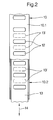
- the outer wall 1 shows a part of a building with a parapet area 1 and on the inside of the parapet area for space heating provided with water-filled heating elements 2, which are arranged at a free distance d in front of the inner wall surface 3.
- a floor ceiling of the building is designated 4.
- the radiator 2 are supported with feet 5.
- the outer wall 1 has a structure intended for the use of solar energy, the details of which are only shown in the middle wall element of the part of the outer wall 1 shown.
- an absorption layer 9 is arranged which absorbs the solar radiation from the air space 8.
- the heat energy obtained in the absorption layer 9 from the solar radiation results in a heat flow directed outwards on the one hand, and a heat flow flowing through the wall shell 6 on the inside of the building and the wall surface 3 into the interior of the building (in each case on the right side of the outer wall 1 in the drawing).
- a cladding 10 is provided on the inside of the building, through which a convection space 11, which is located between the inner wall surface 3 and the heating element 2 and through which the air of the interior of the building can flow, is formed.
- the strength of the air flow flowing through the convection chamber 10 can be adjusted by means of adjustable flow devices.
- the cladding 10 has a top wall 10.1, which overlaps the convection chamber 11 and adjoins the wall inner surface 3 of the outer wall 1, with outlet openings 12 for the air flowing through the convection chamber 11.
- the flow devices adjusting the air flow are formed by suitable closure members 13 for these outlet openings 12.
- Such closure members 13 can be adjustable slides, as in FIGS. 1, 2 and 3, or flaps, as in FIG. 4, the closure members 13 being pulled out in the drawing in their position closing the outlet openings 12 and in their outlet openings 12 completely releasing position 13 'are shown in dashed lines.
- the closure members 13 are adjusted in each case in the direction of the double arrows 14.
- the cladding 10 has a front wall 10.2 which is essentially parallel to the inner wall surface 3 and which adjoins the top wall 10.1 above and below the top wall 10.1 the convection space 11 towards the building interior down to openings 15 provided in the floor area of the building interior for the entry of air into the convection chamber 11.
- the top wall 10.1 and the front wall 10.2 extend continuously over all radiators 2.
- the front wall 10.2 can have a recess 16 for each radiator 2 in which the radiator 2 with its Building interior facing wall 17 is flush with the outer surface of the front wall 10.2 and with its upper edge and its two lateral edges closely adjoins the associated edges of the recess 16.
- FIG. 1 there is also the possibility shown in FIG.
- the closure members 13 forming the flow devices have actuators, not shown in detail, which can be controlled outside and / or inside the building depending on selected climate values.
- climate values can be the outside temperature and the solar energy supply on the one hand and the inside temperature in the building interior and / or the inside surface temperature on the other. Sensors can be provided to record these climate values be, which are also not shown in the drawing.
- the lining 10 can carry a thermal insulation layer 18 on the inner surface facing the convection space 11, which is indicated in FIGS. 3 and 4 only by a thicker stroke width.
- the heating element 2 faces the inner wall surface 3 of the outer wall with a jacket surface 19 that is as closed as possible.
- the convection space 11 is located between these two surfaces 3, 19, so that the air flowing through the convection space 11 can sweep along both surfaces 3, 19.
- the inner wall surface 3 and the outer surface 19 can be adapted to one another with regard to their radiation emissivity. As a result, it can easily be achieved in this way that the heating elements 2, in conjunction with the cladding 10, considerably reduce the heat radiation from the inner wall surface 3, insofar as the latter lies within the convection space 11.
- the heating elements 2 are connected to a heating water circuit, not shown in detail, and are designed as a radiator or convector, which, depending on the individual configuration, may already have the above-mentioned closed jacket surface 19.
- the heating water filling the heating elements 2 forms a heat storage means which can absorb and store heat from the convection space 11, in particular when the outlet openings 12 are more or less closed and thus the air flow through the convection space 11 is throttled or blocked accordingly. So that radiant heat reaching the jacket surface 19 from the inner wall surface 3 can be supplied for storage in the heating water, the jacket surface 19 must, as is the case with convectors anyway, be in good heat conduction connection with the parts of the heater body carrying the heating water.
- the heating body 2 can also be formed by several, spaced and parallel plates.
Landscapes
- Engineering & Computer Science (AREA)
- Physics & Mathematics (AREA)
- Life Sciences & Earth Sciences (AREA)
- Sustainable Development (AREA)
- Sustainable Energy (AREA)
- Thermal Sciences (AREA)
- Chemical & Material Sciences (AREA)
- Combustion & Propulsion (AREA)
- Mechanical Engineering (AREA)
- General Engineering & Computer Science (AREA)
- Building Environments (AREA)
- Load-Bearing And Curtain Walls (AREA)
Applications Claiming Priority (2)
| Application Number | Priority Date | Filing Date | Title |
|---|---|---|---|
| DE19614515 | 1996-04-12 | ||
| DE19614515A DE19614515C1 (de) | 1996-04-12 | 1996-04-12 | Anordnung zur Beeinflussung des zur Gebäudeinnenseite gerichteten Wärmetransports bei einem mit Solarenergie beheizbaren Gebäude |
Publications (2)
| Publication Number | Publication Date |
|---|---|
| EP0801277A2 true EP0801277A2 (fr) | 1997-10-15 |
| EP0801277A3 EP0801277A3 (fr) | 1999-03-03 |
Family
ID=7791108
Family Applications (1)
| Application Number | Title | Priority Date | Filing Date |
|---|---|---|---|
| EP97101784A Withdrawn EP0801277A3 (fr) | 1996-04-12 | 1997-02-05 | Bâtiment avec mur extérieur utilisant l'énergie solaire |
Country Status (4)
| Country | Link |
|---|---|
| EP (1) | EP0801277A3 (fr) |
| DE (1) | DE19614515C1 (fr) |
| HU (1) | HUP9702530A3 (fr) |
| PL (1) | PL184993B1 (fr) |
Families Citing this family (2)
| Publication number | Priority date | Publication date | Assignee | Title |
|---|---|---|---|---|
| DE19805190A1 (de) * | 1998-02-10 | 1999-08-12 | Martin Merkler | Speicherheizkörper für solare Beheizung |
| CN103344002B (zh) * | 2013-06-28 | 2015-11-18 | 宁夏祥河生态环境工程研究院有限公司 | 太阳能冷暖炕 |
Family Cites Families (10)
| Publication number | Priority date | Publication date | Assignee | Title |
|---|---|---|---|---|
| US3957109A (en) * | 1974-10-31 | 1976-05-18 | Worthington Mark N | Solar collector -- heat exchanger |
| DE2708128A1 (de) * | 1977-02-25 | 1978-08-31 | Nipp & Co Ernst | Fassadenelement fuer eine gebaeude- vorhangwand |
| US4237865A (en) * | 1979-03-02 | 1980-12-09 | Lorenz Peter J | Solar heating siding panel |
| DE2932628C2 (de) * | 1979-08-11 | 1985-04-11 | Prof. Dr.-Ing. Friedrich 3000 Hannover Haferland | Einrichtung zur Klimatisierung von Gebäuden |
| DE3230639A1 (de) * | 1982-08-18 | 1984-02-23 | Fraunhofer-Gesellschaft zur Förderung der angewandten Forschung e.V., 8000 München | Waermeschutz und klimatisierung mit fassadenkollektoren |
| DE3236726C2 (de) * | 1982-10-04 | 1986-04-10 | APA Anlagen Planung GmbH, 8755 Alzenau | Verfahren und Vorrichtung zur wärmetechnischen Nutzung von Sonnenenergie |
| US4607791A (en) * | 1984-12-05 | 1986-08-26 | Gantner Phillip E | Hydronic room heating device |
| DE3507876A1 (de) * | 1985-03-06 | 1986-09-11 | Didier-Werke Ag, 6200 Wiesbaden | Verwendung von zementfreien vibriermassen auf basis von aluminiumoxid und/oder zirkoniumdioxid zur herstellung von verschleissteilen |
| DE9116975U1 (de) * | 1990-04-28 | 1995-02-16 | Rud. Otto Meyer-Umwelt-Stiftung, 22047 Hamburg | Anlage zum Heizen und/oder Kühlen eines Gebäudes mit Solarenergie unter Verwendung von transparenter Wärmedämmung |
| ES2107253T3 (es) * | 1993-10-13 | 1997-11-16 | Norsk Hydro As | Estructura de pared externa para edificios, en particular panel en la zona de parapeto de una pared de edificio. |
-
1996
- 1996-04-12 DE DE19614515A patent/DE19614515C1/de not_active Expired - Fee Related
-
1997
- 1997-02-05 EP EP97101784A patent/EP0801277A3/fr not_active Withdrawn
- 1997-04-11 PL PL97319449A patent/PL184993B1/pl not_active IP Right Cessation
- 1997-12-22 HU HU9702530A patent/HUP9702530A3/hu unknown
Also Published As
| Publication number | Publication date |
|---|---|
| PL319449A1 (en) | 1997-10-13 |
| HUP9702530A2 (hu) | 1999-12-28 |
| DE19614515C1 (de) | 1997-10-23 |
| PL184993B1 (pl) | 2003-01-31 |
| HU9702530D0 (en) | 1998-03-02 |
| HUP9702530A3 (en) | 2000-01-28 |
| EP0801277A3 (fr) | 1999-03-03 |
Similar Documents
| Publication | Publication Date | Title |
|---|---|---|
| EP1606556B1 (fr) | Procede pour assurer le reglage de plusieurs echangeurs de chaleur couples en parallele | |
| EP0177657A1 (fr) | Système pour assurer la demande d'énergie d'un local | |
| DE3113285A1 (de) | Heizungs- und lueftungsanlage | |
| EP0028800B1 (fr) | Dispositif pour l'utilisation de la radiation de la chaleur solaire | |
| DE3036661A1 (de) | Zentrale warmwasserheizungsanlage | |
| DE2603706A1 (de) | Elektrisch beheizter konvektor | |
| DE19614515C1 (de) | Anordnung zur Beeinflussung des zur Gebäudeinnenseite gerichteten Wärmetransports bei einem mit Solarenergie beheizbaren Gebäude | |
| DE19614516C1 (de) | Anordnung zur Beeinflussung des zur Gebäudeinnenseite gerichteten Wärmetransports bei einem mit Solarenergie beheizbaren Gebäude | |
| DE3002513C2 (de) | Dach und der davon begrenzte Dachraum für ein solarbeheiztes Haus | |
| DE9205267U1 (de) | Bodenelement | |
| DE1804281A1 (de) | Vorrichtung fuer Raumkonditionierung | |
| DE29903817U1 (de) | Radiator-Konvektor-Einheit | |
| DE1579777C (fr) | ||
| DE102010047089A1 (de) | Heizkörper | |
| DE19514933C2 (de) | Heiz- und/oder Kühlelement aus Speckstein | |
| DE3227147C2 (de) | Temperaturregelsystem für Zentralheizungen | |
| DE3508876A1 (de) | Verfahren und vorrichtung zur klimatisierung von raeumen | |
| DE1579777B2 (de) | Raumheizungsanlage mit waermespeicherofen | |
| DE102014226191A1 (de) | Klimatisierungseinrichtung für einen Raum, Raum oder Gebäude | |
| DE3116872A1 (de) | Klimaboden | |
| DE2110781A1 (de) | Vorrichtung zum Heizen oder Kuehlen von Raeumen | |
| DE29615791U1 (de) | Zweischalige Gebäudefassade | |
| DE2033216A1 (de) | Wärmetauscher insbesondere Heizkörper fur Heizungsanlagen | |
| DE2129850A1 (de) | Elektrische Blockspeicherheizung | |
| DE2940591C2 (de) | Zentralheizungsanlage |
Legal Events
| Date | Code | Title | Description |
|---|---|---|---|
| PUAI | Public reference made under article 153(3) epc to a published international application that has entered the european phase |
Free format text: ORIGINAL CODE: 0009012 |
|
| AK | Designated contracting states |
Kind code of ref document: A2 Designated state(s): AT BE CH DE LI NL SE |
|
| RBV | Designated contracting states (corrected) |
Designated state(s): AT BE CH DE LI NL SE |
|
| PUAL | Search report despatched |
Free format text: ORIGINAL CODE: 0009013 |
|
| AK | Designated contracting states |
Kind code of ref document: A3 Designated state(s): AT BE CH DE LI NL SE |
|
| 17P | Request for examination filed |
Effective date: 19990310 |
|
| 17Q | First examination report despatched |
Effective date: 20010621 |
|
| STAA | Information on the status of an ep patent application or granted ep patent |
Free format text: STATUS: THE APPLICATION IS DEEMED TO BE WITHDRAWN |
|
| 18D | Application deemed to be withdrawn |
Effective date: 20030228 |