EP0801362B1 - Verfahren und Vorrichtung zum Umwandlen des Formats einer Bilddarstellung - Google Patents
Verfahren und Vorrichtung zum Umwandlen des Formats einer Bilddarstellung Download PDFInfo
- Publication number
- EP0801362B1 EP0801362B1 EP97200936A EP97200936A EP0801362B1 EP 0801362 B1 EP0801362 B1 EP 0801362B1 EP 97200936 A EP97200936 A EP 97200936A EP 97200936 A EP97200936 A EP 97200936A EP 0801362 B1 EP0801362 B1 EP 0801362B1
- Authority
- EP
- European Patent Office
- Prior art keywords
- runlength
- signals
- runlengths
- memory
- generated
- Prior art date
- Legal status (The legal status is an assumption and is not a legal conclusion. Google has not performed a legal analysis and makes no representation as to the accuracy of the status listed.)
- Expired - Lifetime
Links
Images





Classifications
-
- G—PHYSICS
- G06—COMPUTING OR CALCULATING; COUNTING
- G06T—IMAGE DATA PROCESSING OR GENERATION, IN GENERAL
- G06T9/00—Image coding
- G06T9/005—Statistical coding, e.g. Huffman, run length coding
-
- G—PHYSICS
- G06—COMPUTING OR CALCULATING; COUNTING
- G06V—IMAGE OR VIDEO RECOGNITION OR UNDERSTANDING
- G06V10/00—Arrangements for image or video recognition or understanding
- G06V10/40—Extraction of image or video features
- G06V10/42—Global feature extraction by analysis of the whole pattern, e.g. using frequency domain transformations or autocorrelation
- G06V10/421—Global feature extraction by analysis of the whole pattern, e.g. using frequency domain transformations or autocorrelation by analysing segments intersecting the pattern
Definitions
- the invention is related to a method for generating a digital image, comprising converting a series of drawing instructions into compressed image data, each drawing instruction controlling assigning pixel values to pixels positioned, in accordance with the drawing instruction, in an image of pixels arranged in rows and columns, said compressed image data containing a series of runlengths and corresponding pixel values, wherein a runlength represents a number of successive pixels with mutually identical pixel values.
- the invention is also related to an apparatus for generating a digital image, comprising input means for receiving drawing signals including instructions for generating in accordance therewith pixel value signals of pixels of an image of pixels arranged in columns and rows, drawing signal execution means for assigning pixel values to pixels positioned in said image of pixels, in accordance with the drawing signals, runlength generation means for generating runlength signals wherein a runlength signal represents a number of successive pixels with mutually identical pixel value signals, and memory means for storing the runlength signals and corresponding pixel value signals generated by the runlength generation means.
- the invention is related to an image reproduction system incorporating the above-mentioned apparatus.
- Such image information can originate from, for example, a text processor or a graphic editing system.
- the image format with symbolic drawing instructions delivered hereby is mostly defined according to a standardised Page Description Language such as for example Post Script (Adobe).
- a raster oriented printer is especting image information in a rasterised format such as a bitmap.
- the image is hereby arranged in columns and rows of pixels where print information is given for each pixel. This print information may consist of one bit which, dependent on the value, indicates a maximal or minimal optical density of a pixel.
- Such image information may be used to control a printer directly.
- a bitmap with grey value information for each pixel is also described as a continuous tone bitmap. Although a printer can not be controlled directly herewith, the advantage of a continuous tone bitmap is that a printer may use an own halftone algorithm tuned to the engine for converting multi value grey value information into two value or binary information.
- the usual methods and apparatuses for converting a Page Description Language to a bitmap do employ a memory for storing the pixel information generated by the separate drawing instructions.
- Such a conversion also called rasterisation, is executed by a special apparatus such as a raster image processor.
- a drawing instruction such as for example an instruction to draw a special character at a special position, is hereby fed to a character generator.
- This character generator generates consequently pixel values (consisting of one or more bits) for the pixels concerned and which values are consequenly stored in a so called bitmap memory. This is repeated for all drawing instructions umtil the complete bitmap is defined. It is important hereby to recognise that the generation of pixel values is a non serial process.
- a drawing instruction may afterwards, for example, substitute pixel values of previous drawing instructions. With other words, all pixels of a bitmap do have their final value only when the last drawing instruction has been processed.
- a raster image processor therefore has to be capable, in principle, to store a complete bitmap.
- the present printers and digital copying systems may have a reproduction resolution of 400 DPI (dots per inch) which results, for 24 bits for each pixel, to approximate 48 MB required memory space for an image with a size of one A4.
- DPI dots per inch
- the patent mentioned herefore discloses how to reduce the required amount of memory to a minimum.
- the drawing instructions are reduced hereto to a series of simpler drawing instructions which are preferably active only on pixels within a special band of the image. Information can, owing to this, be bandwise transmitted to a connected printer.
- the image raster information is further compressed according to a known compression algorithm such as for example runlength compression, LZW compression or JPEG compression
- a known compression algorithm such as for example runlength compression, LZW compression or JPEG compression
- the final bitmap or a part herefrom, is converted to a compressed format.
- runlength compression this leads to a series of runlengths to be read in a given order.
- This series of runlengths defines pixel values of successive pixels arranged according to successive pixel positions. For example pixels arranged within a horizontal image line from left to right and further by each image line form top to down.
- bitmap For compression to be started, at least a part of the bitmap should be known.
- the method according to the invention has as its object to overcome the mentionened disadvantages and is thereto characterised by generating runlengths of pixel values in the execution of each respective drawing instruction, and upon executing a succeeding drawing instruction, which generates pixel values for pixels in positions occupied by pixels generated in a preceding drawing instruction, combining the runlengths generated in said preceding and succeeding drawing instructions without first expanding the respective runlengths into single pixels.
- the apparatus according the invention is characterised in that said drawing signal execution means are integrated in said runlength generation means to generate runlength signals in the execution of each respective drawing instruction, and in that said integrated drawing signal execution and runlength generation means, when executing a succeeding drawing instruction, which generates pixel values for pixels in positions occupied by pixels generated in a preceding drawing instruction, combine the runlength signals generated in said preceding and succeeding drawing instructions without first expanding the respective runlength signals into single pixels.
- said step of combining runlengths includes determining insert positions for runlengths generated by a said succeeding drawing instruction in the series of runlengths generated by a said preceding drawing instructions on the basis of pixel positions of said generated runlengths, inserting said runlengths generated by a said succeeding drawing instruction at said insert positions in the series of runlengths generated by a said preceding drawing instructions according to a prescription for inserting according to which runlengths of the series which have positions in common with runlengths to be inserted, are modified in dependance on the runlengths and pixel values to be inserted.
- Pixels are normally arranged in image rows in a first order as determined by successive pixel positions, but in a further embodiment of the rpesent invention, the runlengths as generated by the drawing instructions are arranged in a second order which is different from that first order.
- a character will not define a complete horizontal row of successive pixels but only a number of local pixels distributed over a number of image lines. The sequence of reading successive pixels of one complete image line differs from the sequence of pixels generated by a character drawing instruction.
- a runlength to be inserted is therefore fitted in the series of runlengths already generated and which are ordered in a first order corresponding to successive pixel positions, thereby modifying the runlengths in the series if necessary.
- runlength compression is based on the insight that the pixel values generated by a drawing instruction, mostly correspond with a number of successive pixels at an image line. For example, a character will cover several successive pixels on an image line.
- a further embodiment of the method is characterised in that the prescription for inserting comprises removing runlengths from the series which are overlapped completely by the runlength to be inserted with respect to pixel position, shortening runlengths from the series which are overlapped partially by the runlength to be inserted with respect to pixel position and which have different pixel values with this with a length equal to the part overlapped, lengthening the runlength to be inserted in case of runlengths of the series which are overlapped partially by the runlength to be inserted with respect to pixel position and which have an identical pixel value with this with a length equal to the part not overlapped followed by removing said runlength for the series, inserting the runlength to be inserted into the series of runlengths.
- An advantageous embodiment of the method is being characterised by dividing the image in subareas of pixels, dividing the series of runlengths and pixel values in subseries whereby each subseries corresponds with a subarea of the image and further inserting the runlengths and pixel values into the subseries which are corresponding with the subareas of said runlengths.
- Inserting a new runlength in the subseries is easier and faster because the number of runlengths in a subseries is restricted. Especially if addressing of a subseries is also fast. Such as for example in case of a subseries which corresponds with an image line or a part of an image line. It is true that some additional administration is needed in order to administer in which subseries a new runlength has to be added. However, because the runlengths originating from one drawing instruction in practice occur in the same subarea, a gain in processing time is achieved.
- an efficient memory management is obtained by making available in first instance a minimal amount of memory space in the addressable memory for each subseries, further determining if there is sufficient memory space available for each runlength and pixel value to be inserted for the corresponding subseries, enlarging the memory space available for the subseries if this is not the case and adapting the address information in the corresponding information word.
- a pixel value corresponding with a runlength does not need to exist of 24 bits but only of 1 bit for the pixel value.
- a further advantageous method is then obtained in which type information is added to the information word for indicating the type of information which is represented by the corresponding subseries.
- the type information may be used to indicate the presence of only one colour.
- a fast method for searching the insert position of a runlength is being chararaterised by splitting a subseries up into two parts such that the available space in the memory for a subseries is positioned between the spaces occupied by the two parts and such that the runlength and pixel value inserted latest occupy the space adjacent to the available space, moving through the runlengths from this available space when searching for a runlength in the subseries, after inserting a runlength to the subseries, moving the runlengths until the inserted runlength is adjacent to the available space. Because a runlength to be inserted is often adjacent to a previously inserted runglength, it is advantageous to make the available space adjacent to the runlength inserted latest. Removing of runlengths in order to make space for a new runlength, can then be avoided.
- EP-A-0575134 disclosing generation of digital images on the basis of drawing instructions in page description language (PDL) form.
- PDL page description language
- a PDL interpreter generates frame description commands defining graphic objects and document layout information describing how to apply the frames onto a bit map raster.
- Graphic objects may include runlengths, but no disclosure is given about the way overlapping objects are combined into a single digital image.
- the image arranged in columns and rows of pixels is divided in sub areas, hereafter called strips. Inserting of runlengths can take place per strip. The advantage off this is that per strip only a limited number of runlengths have to be searched and eventually be moved.
- FIG. 1 it is schematically shown in which way an image 1001 is divided in strips 1002 of each 256 pixels 1003. Each horizontal image line 1004 is further divided in 20 strips 1002.
- an information word 1005 is defined in which the memory addresses are included of the allocated memory space for the strip.
- the allocated memory space for a strip is called hereafter strip buffer.
- the size of a strip buffer can easily be adapted by modifying these memory addresses.
- a series of 32 bits in an address pointer part 1006 is allocated for the start address of a strip buffer. This address pointer part is called hereafter POINTER.
- a second series 1007 of 32 bits is allocated for additional information relating to the strip buffer. Bits 0 and 1 herefrom (TYPE) denote if a strip buffer represents one pixel value (MONO-COLOUR) or several pixel values (FULL-COLOUR). In case of MONO-COLOUR the pixel value is not stored in the strip buffer itself but in the highest order 24 bits (9-31) (COLOUR) of the information word. In this case a strip buffer for storing the length is not required as the runlength with this pixel value is, by definition, equal to the maximum size of a strip (256 pixels). Only in this case the fields described hereafter are not applicable.
- bits 2-31 are defined differently in case of FULL-COLOUR.
- the bits 2-4 then denote the size of the strip buffer. Standard sizes are 4, 8, 16, 32, 128 or 256 bits words. These sizes are coded as 0 up and until 6 respectively.
- the runlengths stored are situated in the strip buffer in such a way that the runlength inserted latest is adjacent to the still available memory space.
- This available memory space is denoted as gap and separates the runlengths stored in a left and a right part.
- the advantage is that inserting a new runlength can be done faster in most cases. A new runlength will often be adjacent to a previously inserted runlength. The extra time necessary for moving the runlengths in the memory when once a runlength can not be inserted adjacent the gap, does not cancel the obtained gain in time in case of insertions directly in the gap.
- the bits 5-13 (RLEN) are representing the number of runlengths to the right (0 -255) and the bits 14-22 (LLEN) are representing the number of runlengths to the left of the gap.
- the pixel position (GAP) is represented by the bits 23-31 (pixel 0 up and until pixel 255). This is thus the pixel coordinate of the strip at the end of the runlength left to the gap (and from the start of the
- a runlength (LEN1, LEN2, ...) is coded with 8 bits (with possible lengths of 1 up and until 256) and the corresponding pixel value with 24 bits (8 bits for red (R), 8 bits for green (G) and 8 bits for blue (B)).
- R red
- G green
- B blue
- 256 several grey values are available for each elementary color.
- an arbitrary colour can be defined by a specfic combination of values of these three elementary colours R, G and B (or by another set of elementary colours such as for example cyan, magenta or yellow).
- the number of runlengths to the left (LLEN) of the gap amounts to 2 and the number of runlengths to the right (RLEN) of the gap amounts to 5.
- the runlength denoted with LEN2 is inserted latest while the pixel position of this runlength is stored as GAP in the bits 23-31 in the information word illustrated in Figure 1.
- FIG 3 finally illustrates schematically a possible arrangement of a memory into a part 3001 with information words 3002 of each two times 32 bits and a part 3003 with strip buffers of each 32 bits words.
- This strip buffer memory 3003 is constituted of an sequence of strip buffers 3004 of different sizes.
- Each information word 3002 points to a strip buffer 3004.
- Figure 4 illustrates a method for inserting new runlengths NRL in one or more strip buffers. Generation of these runlengths on the basis of drawing instructions of a page description language as for example PostScript (Adobe), will be not described further. Such a generation is well known to a skilled man in the art. In practice, for example, an ASCII-code for a character is fed to a symbol generator for generating one or more pixel values of successive pixels. Another possibility is converting relative complex drawing instructions to less complex drawing instructions which also can be used to generate a series of pixel values. The series of pixels generated in this way, are represented, in step 4001, by a new runlength NRL to be inserted.
- a page description language as for example PostScript (Adobe)
- runlength not only the number of successive pixels with indentical pixel values (values herafter to be called colour) is meant but also the corrreponding pixel value or colour.
- the POINTERS for the first and last strip which are possibly to be modified by the new runlength NRL, are determined at step 4002. Pointers are addressable more efficiently then the individual pixels addresses as the pointers can be arranged as a fast addressable matrix covering the entire image.
- decision step 4003 a distinction is made between the case that the new runlength NRL merely covers one strip (step 4004) and the case the new runlength NRL covers several strips (step 4004, 4006 and 4007).
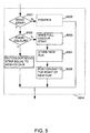
- FIG. 5 The processing of one strip according to step 4004 is illustrated in Figure 5 while the processing of several strips is illustrated in Figure 10 (leftmost strip to be filled or coloured partially), Figure 11 (strips situated between and to be filled or coloured completely) and Figure 12 (rightmost strip to be filled or coloured partially).
- the method illustrated in Figure 4 is repeated until all pixel values generated are stored as a series of runlengths in the corresponding strip buffers.
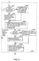
- FIG. 5 illustrates a further embodiment of step 4004 of Figure 4 related to inserting a new runlength in only one strip buffer.
- First is determined, in step 5001, if the strip buffer belongs to the MONO-COLOUR type. When this is this the case and when also is established, in step 5002, that the colour of the new runlength is identical to the colour of the MONO-COLOUR strip buffer, the strip buffer need not to be changed. The processing so far as the new runlength is completed then.
- step 5002 is established that the colour of the new runlength NRL is different from the MONO-COLOUR colour, the strip buffer has to be changed into a FULL-COLOUR strip buffer.
- step 5003 memory space has to be allococated and the previously described TYPE-information has to be changed correspondingly.
- the runlength of the new runlength is, in step 5004, subsequently being stored in the strip buffer where further, in step 5005, is looked for that the available memory space (or gap) is situated to the right of the inserted runlength.
- step 5001 the strip buffer appears to be of the type FULL-COLOUR, a more extensive method 5006 such as described in Figure 6 follows.
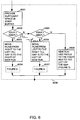
- Figure 6 illustrates the method for inserting a new runlength NRL in a single strip buffer of the FULL-COLOUR type.
- step 6001 is looked for that sufficient space is available in the strip buffer in order to be able to insert the new runlength. This is realised by allocating new memory space, to copy the stored runlengths to this new memory space and deallocating the old memory space. Further the BLEN information in the information word is adapted.
- step 6002 it is established if the pixel coordinate XBNR (in the image line direction) at the beginning of a new runlength is larger than the pixel coordinate XBSPL (in the image line direction) at the end of the gap.
- step 6003 one or more runlengths in the strip buffer are moved, in step 6003, from right to left of the gap such that the gap will be situated to the right of the beginning of the new runlength NRL . Subsequently, in step 6004, the new runlength is inserted.
- step 6005 it is checked if the pixelcoordinate XENR at the end of the new runlength is smaller than the pixelcoordinate XBSPL at the beginning of the gap. Is this the case, thus the new runlength does have pixels to the left of the beginning of the gap, one or more runlengths in the stripbuffer are moved (in step 6006) from left to right of the gap such that the gap is situated to the left of the new runlength. Subsequently, in step 6007, the new runlength is inserted.
- step 6005 If the determination in step 6005 appears to be negative too, then the new runlength does have pixels to the left as well to the right of the gap. In step 6008 the new runlength is inserted.
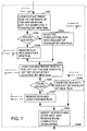
- step 6008 of Figure 6 for inserting a runlength which has pixels to the right as well as to left of the gap is illustrated.
- step 7001 the leftmost runlength to the right of the gap which is not yet covered completely by the new runlength is searched. Subsequently it is being determined, in step 7002, whether this runlength does have the same colour as the new runlength. In case of identical colours, this runlength is, in step 7003, removed and the new runlength is lengthened with the part not covered or overlapped by this runlength. In case of different colours, the runlength of the covered or overlapped runlength is, in step 7004, shortened with an amount which is covered by the new runlength.
- step 7005 the rightmost runlength to the left of the gap which is not yet completely covered by the new runlength is searched. As described before, dependent on if this runlength posesses the same colour as the new runlength, the runlength is either substituted or shortened and the new runlength is lengthened if necessary (steps 7006, 70007 and 7008). Further, the completely covered runlengths are removed.
- step 7009 the new runlength, which may have been lengthened, is inserted and the information in the information word is modified .
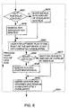
- step 6004 of Figure 6 is illustrated for inserting the new runlength if the runlength is only having pixels to the right of the gap. It is remarked that according to the method illustrated in Figure 6, the gap has moved meanwhile such that the gap is situated now to the right of the beginning of the new runlength.
- step 8001 it is determined if the runlength just to the left of the gap has the same colour as the new runlength. If this is the case, then this runlength is removed and the new runlength is lengthened (step 8002). Otherwise this runlength is shortened with the amount of overlap by the new runlength (step 8003).
- step 8003 the leftmost runlength to the right of the gap which is not yet completely covered by the new runlength.
- This runlength is subsequently either removed and the new runlength lengthened or either this runlength is shortened with the amount of overlap by the new runlength (step 8005, 8006 and 8007). Also again the completely overlapped runlengths are removed.
- step 8008 the new runlength is inserted and the information in the information word corresponding with the the strip buffer is modified.
- Figure 9 illustrates a method analogous as illustrated in Figure 8 but now in case the new runlength only has pixels to the left of the gap. Also again according to the method in Figure 6, the gap is moved such that the gap is situated just to the left of the beginning of the new runlength.
- step 9001 is determined if the runlength just to the right of the gap has the same colour as the new runlength. Is this the case, then, in step 9002, the runlength is removed and the the new runlenght is lengthened with the amount of the not overlapped part of the removed runlength. Otherwise, in step 9003, the runlength is shortened with the amount of overlap by the new runlength.
- step 9004 is looked for the rightmost run to the left of the gap which is not yet completely overlapped by the new runlength. If this runlength has the same colour (step 9005) then the runlength is removed and the new runlength lengthened (step 9006) otherwise the runlength is shortened (step 9007). Finally, in step 9007, the new runlength is inserted and the information in the information word corresponding with the strip buffer is modified. The completely overlapped runlengths are also removed.
- the sitations described thus far are related to the case that the new runlength covers maximal one strip. This is determined in step 4003 of Figure 4. Distinction is then made between sitatuations where the new runlength does have pixels either to the left, to the right or as well to the left and to the right of the gap.
- the processing of thes different sitations is described in the Figures 7, 8 and 9. In the Figures 10, 11 and 12 the processing is described in the situation the new runlength covers more then one strip.
- Figure 10 describes the modifying of the leftmost strip which is partially covered by the new runlength in the case the new runlength covers several strips.
- this partially covered strip is of the MONO-COLOUR type and besides is having the same colour (step 10001 and 10002), then the processing is finished and nothing needs to be modified.
- steps 10004, 10005 and 10006 it is determined if the strip buffers needs to be extended.
- step 10004 determines successively if there is enough space (the gap) available (step 10004), if the beginning of the last runlength is situated to the left of leftmost pixels to be coloured (step 10005) and if the colour of the last runlength is different from the colour of the new runlength (step 1006). If the outcome of these three conditions is positive, then, in step 10007, a new strip buffer with a double size is allocated and the runlengths in the old strip buffer are copied to the new strip buffer. The copied runlengths are situated then to the left of the gap. Subsequently, the new runlength is inserted, in step 10008, to the right of the gap.
- step 10009 it is determined if the gap is situated to the left of the leftmost pixels to be coloured. Is this the case, then, in step 10010, as much as runlengths are moved from the left to the right of the gap until a runlength is obtained which is not yet completely covered by the new runlength. In the other case, in step 10011, as much runlengths are searched from right to the left of the gap until a runlength is found which is not yet completely covered by the new runlength. Subsequently, in step 10012, it is determined if this not completely covered runlength has the same colour. If this is the case, then, in step 10013, the runlength is removed and the new runlength is lengthened.
- step 10014 the runlength is shortened with the amount overlap by the new runlength.
- step 10015 it is determined if the strip has to become a MONO-COLOUR strip.
- the strip is either, in step 10016, changed into a MONO-COLOUR strip or either, in step 10017, the new runlength is inserted in the strip buffer and the information in the corresponding information word is changed.
- Figure 11 illustrates the modifying of strips which are completely covered by the new runlength where the new runlength covers several strips. This is realized by repeatedly (step 11001 and step 11005) performing the following steps for each completely covered strip.
- step 11002 it is determined whether the completely covered strip is of the type MONO-COLOUR. If this is the case, then, in step 11006, the information in the corresponding information word is possibly modified in accordance with the colour of the new runlength. If the strip is not of the type MONO-COLOUR, then, in step 11003, the corresponding memory in the strip buffer is deallocated. Subsequently, in step 11004, the strip is changed into the MONO-COLOUR type with the colour of the new runlength by modifying the corresponding information in the information word.
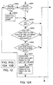
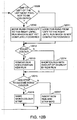
- Figure 12 describes the modifying of the rightmost strip which is partially covered by the new runlength in the case the new runlength covers several strips.
- this partially covered strip is of the MONO-COLOUR type and besides has the same colour (step 12001 and 12002), then the processing is finished and nothing needs to be modified.
- steps 12004, 12005 and 12006 it is determined if the strip buffers needs to be extended.
- step 12004 determines successively if there is enough space (the gap) available (step 12004), if the end of the first runlength is situated to the right of the leftmost pixels not to be coloured (step 12005) and if the colour of the last runlength is different from the colour of the new runlength (step 12006). If the outcome of these three conditions is positive, then, in step 12007, a new strip buffer with a double size is allocated and the runlengths in the old strip buffer are copied to the new strip buffer. The copied runlengths are situated then to the right of the gap. Subsequently, the new runlength is inserted, in step 12008, to the left of the gap.
- step 12009 it is determined if the gap is situated to the left of the leftmost pixels not to be coloured. Is this the case, then, in step 12010, as much as runlengths are moved from the left to the right of the gap until a runlength is obtained which is not yet completely covered by the new runlength.
- step 12011 as much runlengths are searched from left to the right of the gap until a runlength is found which is not yet completely covered by the new runlength.
- step 12012 is determined if this not completely covered runlength has the same colour. Is this the case, then, in step 12013, the runlength is removed and the new runlength is lengthened.
- step 12014 the runlength is shortened with the amount of overlap by the new runlength.
- step 12015 it is determined if the strip has to become a MONO-COLOUR strip. Then, the strip is either, in step 12016, changed into a MONO-COLOUR strip or either, in step 12017, the new runlength is inserted in the strip buffer and the information in the corresponding information word is changed.
- the method described above can be executed by either a general processor which is provided thereto with a dedicated program or either by special developed circuitry.
- This circuitry can be either be of a fixed design or either be programmable such as for example Logic Cell Arrays.
- the choice between available means for executing the described method shall be in each case be made by the man skilled in the art and be based upon considerations related to processing speed, flexibility, costs and so on.
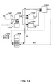
- input means 13001 are depicted for receiving the drawing signals TS. These drawing signals TS are subsequently fed to runlength generation means 13002. This runlength generation means 13002 generate on the basis of a supplied drawing signal TS subsequently one or more new runlength signals NR. Next to this, address information signals corresponding to this runlength signal NR are generated in behalf of address selection means 13003. These address information signals comprise an image area signal BG for selection of a strip buffer which corresponds with this image area, an image line signal SL and a pixel signal XP for the pixel positions covered by the runlength signal NR. The address information generated by the address selection means 13003 are fed to the first memory means 13005. These memory means 13005 allocate subsequently a corresponding memory area in the second memory means 13006. The memory in the memory means 13006 is further divided into strip buffers.
- the new runlength signal NR generated by the runlength generation means 13002 is fed to the first and second selection means 13007 and 13008, together with the relevant runlength signals OR which are stored in the second memory means.
- the first selection means 13007 determine whether the pixel positions of the new runlength signal correspond with the pixel positions of the relevant, stored runlength signals OR. Hereto the address information of the first memory means is fed also to these selection means.
- the second selection means 13008 determine whether the pixel value signal corresponding to the new runlength signal NR differs form the pixel value signal corresponding to an overlapping runlength signal.
- the resulting selection signals S1 and S2 are fed to runlength insertion means 13009, together with the runlength signals NR and OR. These means 13009 modify the runlength signals stored in the second memory means and insert the new runlength signal according to the method as illustrated in the previous figures.
- an image reproduction system for reproducing an image at an image bearing member.
- This system comprises a printer 14002 controlled by a printer controller 14001.
- the printer comprises reproduction means 14007 on the basis of for example a laser or LED with a photo-conductive member or on the basis of inkjet.
- the printer 14002 comprises a page memory 14006 suitable for storage of image signals to be reproduced.
- this memory 14006 receives scan signals SS from an image scanner not depicted in the figure.
- the memory 14006 is filled by data transmission means 14004 and 14005 with image signals.
- These data transmission means preferably comprise of a standarized electrical connection according to the SCSI-standard for example.
- the printer controller 14001 comprises further an apparatus 14003 according Figure 13 for converting drawing signals TS to be fed to the printer controller 14001 to runlength signals NR to be fed to the printer 14002.
- the memory space required in the printer controller 14001 and the capacity required for transport of the signals to the printer 14002 is smaller than in case of converting the runlength signals first to bitmap signals.
- a BI-COLOUR strip can be kept where information regarding two colours can be stored.
- a runlength without pixel values is stored in the strip buffer.
- a first runlength has always the first colour while successive runlengths always have a colour which alternates between the first and the second and other colour.
- Use is needed of only one byte instead of four bytes per runlength.
- the pixel values of the two colours can be stored in the information word corresponding with the strip buffer.
Landscapes
- Engineering & Computer Science (AREA)
- Multimedia (AREA)
- Physics & Mathematics (AREA)
- General Physics & Mathematics (AREA)
- Theoretical Computer Science (AREA)
- Computer Vision & Pattern Recognition (AREA)
- Image Processing (AREA)
- Compression Of Band Width Or Redundancy In Fax (AREA)
- Storing Facsimile Image Data (AREA)
- Controls And Circuits For Display Device (AREA)
- Compression, Expansion, Code Conversion, And Decoders (AREA)
- Record Information Processing For Printing (AREA)
Claims (19)
- Verfahren zum Erzeugen eines digitalen Bildes, mit:
Umwandeln einer Folge von Zeichunbefehlen in komprimierte Bilddaten,
wobei jeder Zeichenbefehl die Zuweisung von Pixelwerten zu Pixeln steuert, die in Übereinstimmung mit dem Zeichenbefehl in einem Bild aus in Zeilen und Spalten angeordneten Pixeln positioniert werden,
wobei die komprimierten Bilddaten eine Folge von Lauflängen und entsprechenden Pixelwerten enthalten,
wobei eine Lauflänge eine Anzahl von aufeinanderfolgenden Pixeln mit untereinander identischen Pixelwerten repräsentiert,
Erzeugen von Lauflängen von Pixelwerten bei der Ausführung jedes einzelnen Zeichenbefehls und
bei Ausführung eines nachfolgenden Zeichenbefehls, der Pixelwerte für Pixel in Positionen erzeugt, die von Pixeln belegt sind, die in einem vorherigen Zeichenbefehl erzeugt wurden,
Kombinieren der in den ersten und nachfolgenden Zeichenbefehlen erzeugten Lauflängen, ohne die betreffenden Lauflängen zuvor in einzelne Pixel zu entfalten. - Verfahren nach Anspruch 1, bei dem der Schritt des Kombinierens von Lauflängen umfaßt:Bestimmen von Einfügepositionen für Lauflängen, die von dem nachfolgenden Zeichenbefehl erzeugt wurden, in die Folge von Lauflängen, die von dem vorherigen Zeichenbefehl erzeugt wurden, auf der Grundlage von Pixelpositionen der erzeugten Lauflängen,Einfügen der von dem nachfolgenden Zeichenbefehl erzeugten Lauflänge an der Einfügeposition in die Folge von Lauflängen, die von dem vorherigen Zeichenbefehl erzeugt wurde,gemäß einer Einfügevorschrift, nach der Lauflängen der Folge, die Positionen mit einzufügenden Lauflängen gemeinsam haben, in Abhängigkeit von den einzufügenden Lauflängen und Pixelwerten modifiziert werden.
- Verfahren nach Anspruch 1,
bei dem Pixel in einer ersten Anordnung, wie sie durch aufeinanderfolgende Pixelpositionen bestimmt wird, in Bildzeilen angeordnet werden und
die Lauflängen, wie sie von den Zeichenbefehlen erzeugt werden, in einer zweiten Anordnung angeordnet werden, die von der ersten Anordnung verschieden ist. - Verfahren nach Anspruch 1, dadurch gekennzeichnet, daß die Einfügevorschrift umfaßt:Entfernen von Lauflängen, die von der in Bezug auf die Pixelposition einzufügenden Lauflänge vollständig überlappt werden, aus der Folge,Kürzen von Lauflängen aus der Folge, die von der in Bezug auf die Pixelposition einzufügenden Lauflänge teilweise überlappt werden und davon verschiedene Pixelwerte haben, um eine Länge, die gleich dem überlappten Teil ist,im Fall von Lauflängen der Folge, die von der in Bezug auf die Pixelposition einzufügenden Lauflänge teilweise überlappt werden und einen damit identischen Pixelwert haben, Verlängern der einzufügenden Lauflänge um eine Länge, die gleich dem nicht überlappten Teil ist, gefolgt von der Entfernung dieser Lauflänge aus der Folge,Einfügen der einzufügenden Lauflänge in die Folge der Lauflängen.
- Verfahren nach Anspruch 1 oder 2, gekennzeichnet durch
Aufteilen des Bildes (1001) in Unterbereiche (1002) von Pixeln (1003),
Aufteilen der Folge von Lauflängen und Pixelwerten in Unterfolgen, wobei jede Unterfolge einem Unterbereich (1002) des Bildes entspricht, und
Einfügen der Lauflängen und Pixelwerte in die Unterfolgen, die mit den Unterbereichen (1002) der Lauflängen korrespondieren. - Verfahren nach Anspruch 5, gekennzeichnet durch
Speichern der Unterfolgen in einem adressierbaren Speicher (13006).
Zuweisen eines Informationswortes (1005) zu jedem Unterbereich (1002),
Hinzufügen von Adresseninformation bezüglich der Adresse der betreffenden Unterfolge im Speicher (13006) zu dem Informationswort (1005). - Verfahren nach Anspruch 6, gekennzeichnet durch
im ersten Zuge, Bereitstellen einer minimalen Menge an Speicherplatz für jede Unterfolge in dem adressierbaren Speicher,
Entscheiden, für die betreffenden Unterfolgen, ob genügend Speicherplatz für jede einzufügende Lauflänge und den Pixelwert vorhanden ist,
Vergrößern des für die Unterfolge verfügbaren Speicherplatzes, wenn dies nicht der Fall ist, und
Anpassen der Adresseninformation in dem entsprechenden Informationswort (1005). - Verfahren nach Anspruch 6, gekennzeichnet durch:Hinzufügen von Typeninformation (1007) zu dem Informationswort (1005), um den Typ der Bildinformation anzuzeigen, der durch die betreffende Unterfolge repräsentiert wird.
- Verfahren nach Anspruch 6, gekennzeichnet durch:Aufteilen einer Unterfolge in zwei Teile in der Weise, daß der im Speicher für eine Unterfolge verfügbare Platz zwischen den von den beiden Teilen eingenommenen Plätzen liegt und daß die Lauflänge und der Pixelwert, die zuletzt eingefügt wurden, den Platz einnehmen, der an den verfügbaren Platz angegrenzt,Durchsuchen der Lauflängen von diesem vefügbaren Platz aus, wenn nach einer Lauflänge in der Teilfolge gesucht wird,nach dem Einfügen einer Lauflänge in die Unterfolge, Bewegen der Lauflängen, bis die eingefügte Lauflänge an den verfügbaren Platz angrenzt.
- Vorrichtung zum Erzeugen eines digitalen Bildes mit:wobei die Einrichtung zur Ausführung von Zeichensignalen in die Einrichtung zur Erzeugung von Lauflängen integriert ist, um Lauflängensignale bei der Ausführung jedes einzelnen Zeichenbefehls zu erzeugen, und wobeieiner Eingabeeinrichtung (13001) zum Empfang von Zeichensignalen (TS) einschließlich Befehlen zur Erzeugung von Pixelwertsignalen von Pixeln eines Bildes aus in Spalten und Zeilen angeordneten Pixeln in Übereinstimmung damit,einer Einrichtung zum Ausführen von Zeichensignalen, zum Zuweisen von Pixelwerten zu Pixeln, die in dem Bild aus Pixeln positioniert sind, in Übereinstimmung mit den Zeichensignalen,einer Einrichtung (13002) zur Erzeugung von Lauflängensignalen (NR), wobei ein Lauflängensignal eine Anzahl von aufeinanderfolgenden Pixeln mit untereinander identischen Pixelwertsignalen repräsentiert, undeiner Speichereinrichtung (13006) zum Speichern der Lauflängensignale und zugehöriger Pixelwertsignale, die von der Einrichtung zur Erzeugung von Lauflängen erzeugt wurden.
die integrierte Einrichtung (13002) zur Ausführung von Zeichensignalen und zur Erzeugung von Lauflängen bei der Ausführung eines nachfolgenden Zeichenbefehls, der Pixelwerte für Pixel in Positionen erzeugt, die von Pixeln belegt sind, die in einem vorherigen Zeichenbefehl erzeugt wurden,
die in den vorherigen und nachfolgenden Zeichenbefehlen erzeugten Lauflängensignale kombiniert, ohne die betreffenden Lauflängensignale zunächst in einzelne Pixel zu entfalten. - Vorrichtung nach Anspruch 10, bei der die integrierte Einrichtung (13002) zur Ausführung von Zeichensignalen und zur Erzeugung von Lauflängen umfaßt:eine Einrichtung zur Bestimmung von Einfügepositionen für Lauflängensignale, die von dem nachfolgenden Zeichenbefehl erzeugt wurden, in die Folge von Lauflängensignalen, die von dem vorherigen Zeichenbefehl erzeugt wurde, auf der Grundlage der Pixelpositionen der erzeugten Lauflängensignale,eine Einrichtung (13009) zum Einfügen der von dem nachfolgenden Zeichenbefehl erzeugten Lauflängensignale an der Einfügeposition in die Folge von Lauflängensignalen, die von dem vorherigen Zeichenbefehl erzeugt wurde,gemäß einer Einfügevorschrift, nach der Lauflängensignale aus der Folge, die Positionen mit einzufügenden Lauflängen gemeinsam haben, in Abhängigkeit von den einzufügenden Lauflängensignalen und Pixelwerten modifiziert werden.
- Vorrichtung nach Anspruch 10 oder 11, bei der die integrierte Einrichtung (13002) zur Ausführung von Zeichensignalen und zur Erzeugung von Lauflängen umfaßt:eine Einrichtung zur Speicherung von Lauflängensignalen, wie sie von den Zeichenbefehlen erzeugt werden, in einer zweiten Anordnung, die von einer ersten Anordnung verschieden ist, wie sie durch aufeinanderfolgende Pixelpositionen in Bildzeilen bestimmt wird.
- Vorrichtung nach Anspruch 10, dadurch gekennzeichnet, daß die Einrichtung zum Einfügen von Lauflängen umfaßt:eine Auswahleinrichtung (13007, 13008) zum Auswählen von ersten bzw. zweiten und dritten Lauflängensignalen, die in der Speichereinrichtung zu speichern sind, wovon alle bzw. ein Teil der Pixelpositionen mit Pixelpositionen eines zweiten Lauflängensignals zusammenfallen, wo die Pixelwertsignale, die dem zweiten bzw. dritten Lauflängensignal entsprechen, nicht identisch bzw. identisch mit dem Pixelwertsignal sind, das dem erzeugten Lauflängensignal entspricht,eine Modifikationseinrichtung (13009) zum Entfernen der ersten Lauflängensignale aus der Speichereinrichtung (13006), zum Begrenzen der Pixelpositionen, die von dem zweiten Lauflängensignal überdeckt werden, auf Pixelpositionen, die von dem erzeugten Lauflängensignal überdeckt werden, zum Erweitern des erzeugten Lauflängensignals auf Pixelpositonen, die von einem dritten Lauflängensignal überdeckt werden, zum Entfernen des dritten Lauflängensignals aus der Speichereinrichtung und zum Speichern des erzeugten Lauflängensignals in der Speichereinrichtung.
- Vorrichtung nach Anspruch 11, dadurch gekennzeichnet, daß
die Speichereinrichtung (13006) in mehrere Speicherbereiche aufgeteilt ist, wobei die Speicherbereiche mit Unterbereichen eines Bildes korrespondieren, das in Unterbereiche aufgeteilt ist, und
die Einrichtung (13009) zum Einfügen von Lauflängen dazu ausgebildet ist, Lauflängensignale und Pixelwertsignale in Speicherbereichen zu speichern, die den Unterbereichen des Signals entsprechen. - Vorrichtung nach Anspruch 14, dadurch gekennzeichnet, daß
die Speichereinrichtung (13006) dazu ausgebildet ist, für jeden Unterbereich (1002) des Bildes ein Informationssignal (1005) zu speichern, wobei
das Informationssignal (1005) ein Adressenreferenzsignal (1006) für den Speicherbereich in der Speichereinrichtung (13006) enthält, der für einen Unterbereich verfügbar ist. - Vorrichtung nach Anspruch 14, dadurch gekennzeichnet, daß die Einrichtung (13009) zum Einfügen von Lauflängen umfaßt;
eine Speicher-Angabeeinrichtung, die dazu ausgebildet ist, im ersten Zug für jeden Unterbereich eine minimale Menge an Speicherplatz in der Speichereinrichtung verfügbar zu machen, wobei
die Speicher-Angabeeinrichtung weiterhin dazu ausgebildet ist, zu entscheiden, ob genügend Speicherplatz für ein erzeugtes Lauflängensignal vorhanden ist, und den angegebenen Speicherplatz zu erweitern, wenn nicht genügend Speicherplatz vorhanden ist, und das Adressenbezugssignal in dem Informationssignal des entsprechenden Unterbereichs zu modifizieren. - Vorrichtung nach Anspruch 14, dadurch gekennzeichnet, daß
die Speichereinrichtung (13006) dazu ausgebildet ist, für jeden Unterbereich (1002) des Bildes ein Typensignal (1007) zu speichern, wobei
das Typensignal den Typ der Bildinformation enthält, die durch die gespeicherten Lauflängensignale des betreffenden Unterbereichs repräsentiert wird. - Vorrichtung nach Anspruch 14, dadurch gekennzeichnet, daß
der Teil jedes Speicherbereiches, der von Lauflängensignalen belegt ist, aufgeteilt ist in zwei Speicher-Unterbereiche, derart, daß der Platz in dem Speicherbereich, der für Lauflängensignale frei ist, zwischen den beiden Plätzen liegt, die von den beiden Speicher-Unterbereichen eingenommen werden, und das zuletzt gespeicherte Lauflängensignal den Platz einnimmt, der an den freien Platz angrenzt,
eine Auswahleinrichtung für Lauflängen bei der Auswahl von Lauflängensignalen die gespeicherten Lauflängensignale von dem freien Platz aus durchsucht und nach der Speicherung eines erzeugten Lauflängensignals die gespeicherten Lauflängensignale in dem Speicherplatz bewegt, bis das gespeicherte erzeugte Lauflängensignal an den freien Platz angrenzt. - Bildwiedergabesystem zur Wiedergabe eines Bildes auf einem Bildträger, mit
einem digitalen Drucker (14002) mit einem Bildspeicher (14006), zur Wiedergabe eines in dem Bildspeicher (14006) gespeicherten Bildes,
einer Steuereinrichtung (14001) für den Drucker, zum Empfang von Seitenbeschreibungssignalen (TS),
einer Datenübertragungseinrichtung (14004, 14005) zum Übertragen von Datensignalen (NR), die von der Steuereinrichtung (14001) erzeugt wurden, an den Bildspeicher (14006) des Druckers (14002), wobei
die Steuereinrichtung (14001) für den Drucker eine Vorrichtung nach einem der Ansprüche 1 bis 18 aufweist, wobei die Seitenbeschreibungssignale den Zeichensignalen und die erzeugten Datensignale den Lauflängensignalen und Pixelwertsignalen entsprechen.
Applications Claiming Priority (2)
| Application Number | Priority Date | Filing Date | Title |
|---|---|---|---|
| US08/627,110 US5726760A (en) | 1996-04-03 | 1996-04-03 | Method and apparatus for converting image representation formats as well as an image production system provided with such an apparatus |
| US627110 | 2000-07-27 |
Publications (3)
| Publication Number | Publication Date |
|---|---|
| EP0801362A2 EP0801362A2 (de) | 1997-10-15 |
| EP0801362A3 EP0801362A3 (de) | 1999-07-07 |
| EP0801362B1 true EP0801362B1 (de) | 2005-11-09 |
Family
ID=24513222
Family Applications (1)
| Application Number | Title | Priority Date | Filing Date |
|---|---|---|---|
| EP97200936A Expired - Lifetime EP0801362B1 (de) | 1996-04-03 | 1997-04-01 | Verfahren und Vorrichtung zum Umwandlen des Formats einer Bilddarstellung |
Country Status (5)
| Country | Link |
|---|---|
| US (1) | US5726760A (de) |
| EP (1) | EP0801362B1 (de) |
| JP (1) | JP3174743B2 (de) |
| CA (1) | CA2199318A1 (de) |
| DE (1) | DE69734541T2 (de) |
Families Citing this family (4)
| Publication number | Priority date | Publication date | Assignee | Title |
|---|---|---|---|---|
| US6362847B1 (en) | 1999-06-15 | 2002-03-26 | Lexmark International, Inc. | Electronic control arrangement for a laser printer |
| DE10012521C2 (de) * | 2000-03-15 | 2002-12-19 | Heidelberger Druckmasch Ag | Verfahren zur Komprimierung von Druckdaten |
| DE10204751B4 (de) * | 2002-02-06 | 2005-03-03 | Heidelberger Druckmaschinen Ag | Verfahren zur Konvertierung eines Linework Datenformats in das Format einer Seitenbeschreibungssprache |
| JP4642620B2 (ja) * | 2004-09-29 | 2011-03-02 | 富士フイルム株式会社 | ランレングス圧縮データの位置特定方法および装置 |
Family Cites Families (8)
| Publication number | Priority date | Publication date | Assignee | Title |
|---|---|---|---|---|
| US4542413A (en) * | 1983-08-19 | 1985-09-17 | Advanced Micro Devices, Inc. | Facsimile device for run length coding |
| US4821336A (en) * | 1987-02-19 | 1989-04-11 | Gtx Corporation | Method and apparatus for simplifying runlength data from scanning of images |
| DE3823674A1 (de) * | 1988-07-13 | 1990-01-18 | Philips Patentverwaltung | Verfahren zum uebertragen von bildern und anordnung zur durchfuehrung des verfahrens |
| US5095512A (en) * | 1988-10-24 | 1992-03-10 | Netexpress Systems, Inc. | Method and apparatus for manipulating image data employing an intermediate format |
| SG49820A1 (en) * | 1992-06-15 | 1998-06-15 | Canon Kk | Method and apparatus for printing according to a graphic language |
| US5539865A (en) * | 1992-11-10 | 1996-07-23 | Adobe Systems, Inc. | Method and apparatus for processing data for a visual-output device with reduced buffer memory requirements |
| US5500928A (en) * | 1993-03-01 | 1996-03-19 | Xionics Document Technologies, Inc. | Digital printing system and process using adaptive compression |
| US5552832A (en) * | 1994-10-26 | 1996-09-03 | Intel Corporation | Run-length encoding sequence for video signals |
-
1996
- 1996-04-03 US US08/627,110 patent/US5726760A/en not_active Expired - Lifetime
-
1997
- 1997-03-06 CA CA002199318A patent/CA2199318A1/en not_active Abandoned
- 1997-04-01 EP EP97200936A patent/EP0801362B1/de not_active Expired - Lifetime
- 1997-04-01 DE DE69734541T patent/DE69734541T2/de not_active Expired - Lifetime
- 1997-04-03 JP JP10103897A patent/JP3174743B2/ja not_active Expired - Fee Related
Also Published As
| Publication number | Publication date |
|---|---|
| US5726760A (en) | 1998-03-10 |
| EP0801362A2 (de) | 1997-10-15 |
| JP3174743B2 (ja) | 2001-06-11 |
| DE69734541D1 (de) | 2005-12-15 |
| JPH1083267A (ja) | 1998-03-31 |
| CA2199318A1 (en) | 1997-10-03 |
| EP0801362A3 (de) | 1999-07-07 |
| DE69734541T2 (de) | 2006-07-20 |
Similar Documents
| Publication | Publication Date | Title |
|---|---|---|
| US5946451A (en) | Method for generating a contone map | |
| KR100561915B1 (ko) | 효율적 안티-앨리어싱을 위해 프레임 버퍼를 동적으로할당하는 방법 및 시스템 | |
| US4974171A (en) | Page buffer system for an electronic gray-scale color printer | |
| US4819063A (en) | Data processing system with common channel for image and character data | |
| EP0235456A2 (de) | Bildverarbeitungsgerät | |
| EP0707730B1 (de) | Seitenzusammensetzungssystem | |
| US5003494A (en) | Data storage system for an electronic color printer | |
| JP2830690B2 (ja) | 画像処理装置 | |
| US7031019B1 (en) | Printer control apparatus, printer and printing system | |
| EP0544416B1 (de) | Druckerseitenzusammensetzung mit Farben und Text | |
| US7139099B2 (en) | Image processing device and image processing method | |
| US7443544B2 (en) | Accelerating color conversion using a temporary palette cache | |
| US5195175A (en) | Image synthesizing system | |
| US6088124A (en) | Color image processing apparatus and method | |
| US5726760A (en) | Method and apparatus for converting image representation formats as well as an image production system provided with such an apparatus | |
| JP3285930B2 (ja) | 画像処理装置 | |
| US6850338B1 (en) | Method, system, program, and data structure for generating raster objects | |
| US5299292A (en) | Reduction printing apparatus | |
| US5109272A (en) | Method of superimposing color images and color image processing apparatus | |
| US5672016A (en) | Method for controlling color image data | |
| JP3636891B2 (ja) | カラー画像出力方法 | |
| JPH09186898A (ja) | 画像処理装置及びその方法 | |
| JP2547716B2 (ja) | デ−タ処理システム | |
| JP3244745B2 (ja) | 画像処理装置 | |
| JP3377298B2 (ja) | カラー画像印刷システム |
Legal Events
| Date | Code | Title | Description |
|---|---|---|---|
| PUAI | Public reference made under article 153(3) epc to a published international application that has entered the european phase |
Free format text: ORIGINAL CODE: 0009012 |
|
| AK | Designated contracting states |
Kind code of ref document: A2 Designated state(s): DE FR GB NL |
|
| PUAL | Search report despatched |
Free format text: ORIGINAL CODE: 0009013 |
|
| AK | Designated contracting states |
Kind code of ref document: A3 Designated state(s): DE FR GB NL |
|
| 17P | Request for examination filed |
Effective date: 20000107 |
|
| 17Q | First examination report despatched |
Effective date: 20040830 |
|
| GRAP | Despatch of communication of intention to grant a patent |
Free format text: ORIGINAL CODE: EPIDOSNIGR1 |
|
| GRAS | Grant fee paid |
Free format text: ORIGINAL CODE: EPIDOSNIGR3 |
|
| GRAA | (expected) grant |
Free format text: ORIGINAL CODE: 0009210 |
|
| AK | Designated contracting states |
Kind code of ref document: B1 Designated state(s): DE FR GB NL |
|
| REG | Reference to a national code |
Ref country code: GB Ref legal event code: FG4D |
|
| REF | Corresponds to: |
Ref document number: 69734541 Country of ref document: DE Date of ref document: 20051215 Kind code of ref document: P |
|
| ET | Fr: translation filed | ||
| PLBE | No opposition filed within time limit |
Free format text: ORIGINAL CODE: 0009261 |
|
| STAA | Information on the status of an ep patent application or granted ep patent |
Free format text: STATUS: NO OPPOSITION FILED WITHIN TIME LIMIT |
|
| 26N | No opposition filed |
Effective date: 20060810 |
|
| REG | Reference to a national code |
Ref country code: FR Ref legal event code: PLFP Year of fee payment: 20 |
|
| PGFP | Annual fee paid to national office [announced via postgrant information from national office to epo] |
Ref country code: NL Payment date: 20160407 Year of fee payment: 20 |
|
| PGFP | Annual fee paid to national office [announced via postgrant information from national office to epo] |
Ref country code: GB Payment date: 20160421 Year of fee payment: 20 Ref country code: DE Payment date: 20160421 Year of fee payment: 20 |
|
| PGFP | Annual fee paid to national office [announced via postgrant information from national office to epo] |
Ref country code: FR Payment date: 20160421 Year of fee payment: 20 |
|
| REG | Reference to a national code |
Ref country code: DE Ref legal event code: R071 Ref document number: 69734541 Country of ref document: DE |
|
| REG | Reference to a national code |
Ref country code: NL Ref legal event code: MK Effective date: 20170331 |
|
| REG | Reference to a national code |
Ref country code: GB Ref legal event code: PE20 Expiry date: 20170331 |
|
| PG25 | Lapsed in a contracting state [announced via postgrant information from national office to epo] |
Ref country code: GB Free format text: LAPSE BECAUSE OF EXPIRATION OF PROTECTION Effective date: 20170331 |