EP0801451A2 - Arrangement accordable - Google Patents
Arrangement accordable Download PDFInfo
- Publication number
- EP0801451A2 EP0801451A2 EP97105831A EP97105831A EP0801451A2 EP 0801451 A2 EP0801451 A2 EP 0801451A2 EP 97105831 A EP97105831 A EP 97105831A EP 97105831 A EP97105831 A EP 97105831A EP 0801451 A2 EP0801451 A2 EP 0801451A2
- Authority
- EP
- European Patent Office
- Prior art keywords
- grating
- resonator
- mirror
- axis
- rotation
- Prior art date
- Legal status (The legal status is an assumption and is not a legal conclusion. Google has not performed a legal analysis and makes no representation as to the accuracy of the status listed.)
- Granted
Links
Images



Classifications
-
- H—ELECTRICITY
- H01—ELECTRIC ELEMENTS
- H01S—DEVICES USING THE PROCESS OF LIGHT AMPLIFICATION BY STIMULATED EMISSION OF RADIATION [LASER] TO AMPLIFY OR GENERATE LIGHT; DEVICES USING STIMULATED EMISSION OF ELECTROMAGNETIC RADIATION IN WAVE RANGES OTHER THAN OPTICAL
- H01S5/00—Semiconductor lasers
- H01S5/10—Construction or shape of the optical resonator, e.g. extended or external cavity, coupled cavities, bent-guide, varying width, thickness or composition of the active region
- H01S5/14—External cavity lasers
- H01S5/141—External cavity lasers using a wavelength selective device, e.g. a grating or etalon
- H01S5/143—Littman-Metcalf configuration, e.g. laser - grating - mirror
-
- H—ELECTRICITY
- H01—ELECTRIC ELEMENTS
- H01S—DEVICES USING THE PROCESS OF LIGHT AMPLIFICATION BY STIMULATED EMISSION OF RADIATION [LASER] TO AMPLIFY OR GENERATE LIGHT; DEVICES USING STIMULATED EMISSION OF ELECTROMAGNETIC RADIATION IN WAVE RANGES OTHER THAN OPTICAL
- H01S3/00—Lasers, i.e. devices using stimulated emission of electromagnetic radiation in the infrared, visible or ultraviolet wave range
- H01S3/10—Controlling the intensity, frequency, phase, polarisation or direction of the emitted radiation, e.g. switching, gating, modulating or demodulating
- H01S3/105—Controlling the intensity, frequency, phase, polarisation or direction of the emitted radiation, e.g. switching, gating, modulating or demodulating by controlling the mutual position or the reflecting properties of the reflectors of the cavity, e.g. by controlling the cavity length
-
- H—ELECTRICITY
- H01—ELECTRIC ELEMENTS
- H01S—DEVICES USING THE PROCESS OF LIGHT AMPLIFICATION BY STIMULATED EMISSION OF RADIATION [LASER] TO AMPLIFY OR GENERATE LIGHT; DEVICES USING STIMULATED EMISSION OF ELECTROMAGNETIC RADIATION IN WAVE RANGES OTHER THAN OPTICAL
- H01S3/00—Lasers, i.e. devices using stimulated emission of electromagnetic radiation in the infrared, visible or ultraviolet wave range
- H01S3/10—Controlling the intensity, frequency, phase, polarisation or direction of the emitted radiation, e.g. switching, gating, modulating or demodulating
- H01S3/105—Controlling the intensity, frequency, phase, polarisation or direction of the emitted radiation, e.g. switching, gating, modulating or demodulating by controlling the mutual position or the reflecting properties of the reflectors of the cavity, e.g. by controlling the cavity length
- H01S3/1055—Controlling the intensity, frequency, phase, polarisation or direction of the emitted radiation, e.g. switching, gating, modulating or demodulating by controlling the mutual position or the reflecting properties of the reflectors of the cavity, e.g. by controlling the cavity length one of the reflectors being constituted by a diffraction grating
-
- H—ELECTRICITY
- H01—ELECTRIC ELEMENTS
- H01S—DEVICES USING THE PROCESS OF LIGHT AMPLIFICATION BY STIMULATED EMISSION OF RADIATION [LASER] TO AMPLIFY OR GENERATE LIGHT; DEVICES USING STIMULATED EMISSION OF ELECTROMAGNETIC RADIATION IN WAVE RANGES OTHER THAN OPTICAL
- H01S5/00—Semiconductor lasers
- H01S5/02—Structural details or components not essential to laser action
- H01S5/022—Mountings; Housings
- H01S5/023—Mount members, e.g. sub-mount members
- H01S5/02325—Mechanically integrated components on mount members or optical micro-benches
Definitions
- the present invention relates to a tuning device for semiconductor diode lasers with an external resonator according to the preamble of claims 1, 13 and 14.
- a semiconductor laser diode operated in the direction of flow can be used to generate coherent light by means of stimulated emission and to emit it in a directed manner.
- the wavelength of the emitted laser light is determined by the respective stoichiometry and the microscopic structure of the semiconductor laser material.
- Typical emission wavelengths of semiconductor laser diodes are between 630nm and 1550nm.
- the laser resonator For some applications of semiconductor lasers, it is necessary to introduce optical elements into the laser resonator, for which an external resonator is used.
- the light emitted by a laser facet is collimated and fed back into the semiconductor laser with a separate (external) resonator end mirror.
- the laser facet facing the external resonator is generally antireflection-coated in order to ensure better coupling of the external resonator to the semiconductor laser.
- the emission wavelength can be tuned over the amplification range of the laser.
- Typical bandwidths are between 12nm and 120nm, depending on whether semiconductor laser diodes with an emission wavelength of 630nm or those with an emission wavelength of 1550nm are used.
- a Littrow arrangement is a resonator that contains an optical diffraction grating as a resonator end mirror, the directions of the incident and the to the Lattice furrows scattered back, positively interfering light collapse.
- the Littman arrangement is a folded resonator that contains a diffraction grating between the resonator end mirrors. In this arrangement the grating is positioned within the resonator so that the first order of diffraction of the grating meets the resonator end mirror. The zeroth diffraction order of the grating can then be used as the useful beam of the laser.
- the grating thus has a double function as a wavelength-selective element and as a coupling-out element.
- the advantage of the Littman arrangement is that the illuminated grid area is a factor of 4 to 7 larger than that of the Littrow arrangement. As a result, the spectral selectivity of the grating is increased by the same factor, so that single-mode laser emission is ensured with the Littman arrangement with larger resonator lengths and very small line widths are thus achieved.
- Another advantage is that commercially available semiconductor lasers are often only supplied in housing designs that do not allow access to the rear laser facet, which is required in the Littrow arrangement as an output mirror.
- the resonator length is kept constant when tuning the emission wavelength of the laser system, the number m of nodes of the standing light wave in the laser resonator changes, which is referred to as a mode jump.
- Mode jumps can be avoided by varying the optical resonator length L opt when tuning the wavelength so that the resulting wavelength ⁇ R tracks the wavelength ⁇ G determined by the grating.
- the condition must 2 L opt ⁇ G - m ⁇ 1 2nd remain fulfilled.
- a measure of the quality of compensation is the number i up to which the development coefficients n i can be taken into account. It is called "compensation of the j -th order dispersion" if the terms n i up to and including the term n j are taken into account exactly.
- Mode-shift-free wavelength tuning of a semiconductor laser with an external resonator over ranges greater than 60 nm - 80 nm is generally only possible if the second-order dispersion is taken into account exactly and the third-order dispersion at least approximately.
- Favre presents a semiconductor laser structure in a Littrow arrangement, in which the global chromatic dispersion of the semiconductor laser, the imaging optics and the air in the external resonator can be compensated by means of an adjusting screw, but only the first-order dispersion.
- mode-shift-free wavelength tuning is not possible over the entire amplification range of the laser; rather, mode jumps occur, which is due to insufficient compensation of the contributions of the second and higher order of the chromatic dispersion of the laser system.
- the invention serves the general aim of providing means for generating coherent light with a continuously and quickly tunable wavelength of a small spectral line width.
- a simple tuning device for a semiconductor laser with an external resonator is to be realized, which enables mode-jump-free wavelength tuning over the entire amplification range of semiconductor lasers in a Littman arrangement.
- a tuning device for a semiconductor diode laser provided with an anti-reflection coating and having an external resonator in a Littman arrangement, consisting of at least one optical transmission component, for example a collimator, furthermore an optical diffraction grating, a tuning arm which can be rotated about an axis and to which a resonator end mirror is attached, as well as adjusting devices for the position of the tuning arm and for the distance between the mirror plane and the axis of rotation to compensate for the first-order chromatic dispersion of all components contained in the laser (e.g.
- the invention provides, according to the characterizing part of claim 1, that the grating is arranged at different angles for the targeted adjustment and compensation of the chromatic dispersion of higher orders net and variable in relation to the axis of rotation of the tuning arm. If the tuning arm is now rotated, this causes translation and rotation of the resonator end mirror at the same time. As a result of its displacement, the geometric resonator length L geo changes , and consequently also the optical one in accordance with equations (2) and (3) Resonator length L opt and therefore the wavelength ⁇ R determined by the resonator.
- the rotation of the resonator end mirror causes a change in the wavelength ⁇ G determined by the grating. This is done according to the invention in such a way that equation (1) remains fulfilled at all times by synchronizing the change in the wavelength ⁇ G determined by the grating.
- the tuning device means a considerable advance over the publication WO 94/08371. Only a single device for compensation is provided there, so that only the first order chromatic dispersion can be compensated for. A non-correctable default setting is selected for 2nd order chromatic dispersion.
- the refractive index of semiconductor lasers is a complicated function of the wavelength, at least the 3rd order contribution of the chromatic dispersion ( n 3 ) must be taken into account for a sufficiently precise compensation in the amplification range of semiconductor lasers. If this is dispensed with, there is an upper limit of the mode jump-free tuning range at approx. 60 nm to 80 nm for 1.55 ⁇ m laser diodes.
- mode-jump-free wavelength tuning is possible over the entire amplification range of semiconductor laser diodes, in that the second-order dispersion can be compensated exactly and the third-order dispersion can be compensated for almost exactly.
- an adjustment means for translating the resonator end mirror in the direction of the mirror normal is available for adjusting the distance between the axis of rotation and the mirror plane.
- this can be a large-caliber fine-thread screw, on which the mirror is fastened so that its normal runs parallel to the screw axis.
- the resonator end mirror is a right-angled prism in accordance with claim 5 such that the light beam coming from the grating penetrates into the prism via the hypotenuse surface, experiences total reflection one after the other on the two catheter surfaces and then out of the prism via the hypotenuse surface emerges, the line of intersection of the prism catheter surfaces perpendicular to the furrows of the grid. Thanks to this alignment of the prism, the optimal quality of the laser resonator is achieved without impairing the wavelength selectivity guaranteed of the grid. This makes the resonator largely insensitive to adjustment errors, which means that the laser can be used under harsh everyday conditions.
- the feature of claim 7 is very advantageous, according to which the grille is fastened on a grille holder with two degrees of freedom of adjustment.
- the grid holder can in particular be rotatable in two directions with the aid of adjusting means, the axes of rotation being perpendicular to one another.
- a first direction of rotation runs along an axis of the grating holder, which allows the adjustment of the resonator quality.
- a second direction of rotation runs along an axis of the grating holder, as a result of which the angle of incidence of the light emitted by the semiconductor diode laser on the grating can be adjusted.
- the two axes of rotation span a plane that runs parallel to the lattice plane. This arrangement contributes greatly to the convenient and reliable adjustability.
- claim 11 For changing the distance between the grating plane and the axis of rotation of the tuning arm, claim 11 provides a sliding table on which the grating holder is fastened together with the grating. This arrangement is very stable. According to claim 12, a fine-thread screw is provided as an adjusting means for the translation of the grating and the grating holder, preferably in the direction of the grating normal, so that the distance adjustment can be carried out very precisely.
- the invention provides, according to independent claim 13, a combination which has a two-dimensional arrangement for the targeted adjustment and compensation of the chromatic dispersion of higher orders in such a way that the grating is mounted on a grating holder in such a way that it can be varied in angle, and that it is mounted on a Sliding table with which the grille is variable in relation to the pivot point of the tuning arm.
- a working level is defined in which the required compensation settings can be done quickly and effectively.
- the tuning device which is characterized in that the grating is mounted on a grating holder so that the angle of incidence of the light emitted by semiconductor diode lasers can be adjusted onto the grating for the targeted adjustment and compensation of the higher order chromatic dispersion is variable, while the lattice holder is mounted on a sliding table such that the distance between the lattice plane and the pivot point of the tuning arm is adjustable.
- the three relevant setting options are combined in this combination in a simple and clear manner.
- a semiconductor laser 1 has a mirror facet which is provided with an anti-reflection coating 2 and which faces the external resonator.
- a lens 3 collimates the laser light emitted by the mirror facet, which strikes the surface of a diffraction grating 4 at an angle of incidence ⁇ 1 .
- Light of the zeroth diffraction order 5 is coupled out as a useful beam from the laser.
- Light of the first diffraction order 6 strikes the external resonator end mirror 7, is reflected there and, after it has been diffracted a second time by the grating 4, is fed back into the laser 1.
- the mirror 7 is fastened on a tuning arm 8 and is rotatably mounted about an axis of rotation 9 parallel to the mirror plane 701. If the tuning arm 8 is rotated about the axis of rotation 9, the wavelength ⁇ G determined by the grating 4 changes and at the same time the wavelength ⁇ R determined by the resonator length.
- FIG. 1B shows a main section of a prism 15.
- the section plane is spanned by two intersecting normals of the catheter surfaces 152 and 153.
- a beam coming from the grating 4 and running in this plane penetrates into the prism 15 via the hypotenuse surface 151, is successively totally reflected on the catheter surfaces 152, 152 and leaves the prism 15 again via the hypotenuse surface 151.
- Incoming beam 61 and outgoing beam 62 are anti-parallel to each other.
- the outgoing beam 62 hits the collimator lens 3 after diffraction at the grating 4, it is fed back into the semiconductor laser 1, largely independently of the angle to the hypotenuse surface 151.
- 1C shows a section through the cylindrical lens 16 and the resonator end mirror 7, such that the sectional plane is perpendicular to the longitudinal axis 162 of the cylindrical lens 16.
- a beam coming from the grating and running in this plane and parallel to the optical axis of the cylindrical lens is refracted in the direction of the optical axis of the cylindrical lens 16, reflected on the mirror plane 701 and then refracted a second time on the cylindrical lens 16.
- the distance between the cylindrical lens 16 and the mirror plane 701 is chosen equal to the focal length of the cylindrical lens 16 on the mirror side, then the incident beam 61 and the emerging beam 62 are antiparallel to one another.
- the incident beam 62 hits the collimator lens 3 after the diffraction at the grating 4, it is fed back into the semiconductor laser 1, largely independently of the angle of the mirror plane 701 to the incident 61 and incident beam 62.
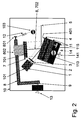
- the one-sided anti-reflection coated semiconductor diode laser 1 is fixedly mounted together with the collimator lens 3 on a base plate 10 on which the grating 4 is also fastened together with the grating holder 11.
- the tuning arm 8, which carries the external resonator end mirror 7, is connected to the base plate 10 in such a way that it can only rotate along the axis of rotation 9.
- a return spring 12 presses the tuning arm 8 against an adjusting unit 13, which preferably consists of a micrometer screw and a piezotranslator, and controls the precise setting of the tuning arm 8.
- the micrometer screw If the micrometer screw is turned or the electrical voltage applied to the piezotranslator is changed, this simultaneously causes a rotation and a translation of the resonator end mirror 7.
- the rotation changes the angle of reflection ⁇ 2 (FIG. 5) of the light of the first diffraction order, ie the tuning steel 6 and consequently the wavelength ⁇ G determined by the grating 4.
- the translation changes the resonator length L opt and thus the wavelength ⁇ R determined thereby.
- FIG. 2 also shows a sliding table 14, the components of which are shown more clearly in FIGS. 3A and 3B.
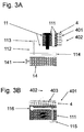
- the lattice holder 11 consists of an upper part 111 and a lower part 112 which are screwed together and fastened on a sliding table 14.
- the lower part 112 of the grid holder 11 is a bending element which is pressed apart by a fine-thread screw 113.
- the grid 4 is rotated about an axis 114 which is at least approximately parallel to the grid plane 401 and is perpendicular to the grid furrows 403. This setting option allows the resonator quality to be adjusted.
- the displacement table 14 also has a fine-thread screw 141, the rotation of which enables the grid holder 11 and the grid 4 to be translated in a direction which corresponds at least approximately to the direction of the grid normal 402. This degree of freedom of adjustment serves to determine the mode jump-free wavelength tuning range.
- FIG. 3B shows a section through the upper part 111 of the lattice holder 11 (cf. FIG. 3A).
- the upper part 111 is also a bending element which is pressed apart by a fine-thread screw 115, the rotation of which causes the grating 4 to rotate about an axis 116 parallel to the grating grooves 403. This also contributes to the setting of the maximum mode jump-free wavelength tuning range.
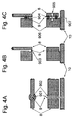
- FIGS. 4A, 4B, 4C show possible implementations of the tuning arm 8.
- It carries a screw 801 to which the return spring 12 can be fastened.
- the resonator end mirror 7 is seated on a large-caliber fine-thread screw 802, which is screwed into the tuning arm and, by its rotation, allows the mirror 7 to be translated in the direction of the mirror normal 702.
- the axis of rotation 9 is a metal rod 901, which is rotatably connected to the tuning arm 8 via bearings 902 and to the base plate 10.
- the tuning arm 8 is also firmly seated on the base plate 10, but it has a constriction 903 which acts as an axis of rotation 9.
- 4C illustrates a tuning arm 8, which is connected via two balls 904 and a spring 905 to a rod 906, which in turn is fastened on the base plate 10.
- the axis of rotation 9 lies in the connecting line 907 of the centers of the balls 904.
- the distance x 2 between the axis of rotation 9 and the mirror plane 701 is adjustable.
- the latter contains straight lines which run parallel to the axis of rotation 9, as a result of which the geometric definition of the term for the distance between point and straight line can be used in the usual way.
- Rotation and translation of the resonator end mirror 7 are synchronized so that the wavelength ⁇ G determined by the grating 4 and the wavelength ⁇ R determined by the resonator length L opt differ by less than a quarter of the wavelength (see. Eq. (1)). Because the refractive index of semiconductor lasers, in contrast to that of a gas laser or dye laser, for example, has a considerable chromatic dispersion, the geometric length L geo differs according to Eq. (3) considerably of the optical length L opt .
- the adjustment means present in the tuning device according to the invention now enable compensation in a surprisingly simple and reliable manner.
- the adjusting screw 802 is used to compensate for the 1st order dispersion of all components contained in the laser resonator (semiconductor laser 1, anti-reflection coating 2, collimator optics 3, air).
- the second-order dispersion is exactly compensated by means of the fine-thread screw 141.
- the fine-thread screw 115 allows the compensation of the 3rd order dispersion and a preselection of the compensation of the 4th order dispersion.
- ⁇ 1 denotes the angle of incidence of the light emitted by the laser 1 onto the grating 4; it can be adjusted using the adjusting screw 115.
- x 1 the distance between the grid plane 401 and the pivot point 9 of the tuning arm 8 is designated.
- This distance x 1 is adjusted by translating the grating 4 in the direction of the grating normal 403, specifically by turning the adjusting screw 141 of the displacement table 14, which causes the grating holder 11 to be translated together with the grating 4.
- the tuning device according to the invention is not only of relatively robust construction, but is also extremely sensitive to use and, for the first time, makes it possible to tune the emission wavelength of semiconductor diode lasers over the entire amplification range without a jump in mode.
- Computed values for the tuning range are many times above the amplification range of semiconductor lasers. Therefore, there is even a large tolerance range for the selection of the aforementioned adjustment means (802, 141, 115), with which the adjustment process can be carried out quickly and safely.
- the resonator quality is largely insensitive to external disturbances that cause adjustment errors can.
- the wavelength tuning behavior when rotating the tuning arm 8 about the axis of rotation 9 is retained without the spectral selectivity of the grating resonator being influenced.
- the invention is not limited to the examples shown and described, but can be modified in many ways. However, one recognizes that in a preferred embodiment of a semiconductor diode laser 1 with an antireflection coating 2, collimator optical system 3, reflection diffraction grating 4, and resonator 7 in Littman configuration exit angle ⁇ 2 of the grating and the geometrical cavity length L geo are mechanically linked to the chromatic dispersion of all the Media contained resonator (semiconductor diode laser 1, anti-reflective coating 2, collimator optics 3, air) when rotating the mirror 7 about the axis of rotation 9 to compensate so precisely that in any case the compensation for the dispersion of the first, second and third order with the aid of adjusting means 802, 141, 115 is effected and thus step-free wavelength tuning is reliably ensured over the entire amplification range of the semiconductor diode laser 1.
Landscapes
- Physics & Mathematics (AREA)
- Condensed Matter Physics & Semiconductors (AREA)
- General Physics & Mathematics (AREA)
- Electromagnetism (AREA)
- Optics & Photonics (AREA)
- Semiconductor Lasers (AREA)
Applications Claiming Priority (4)
| Application Number | Priority Date | Filing Date | Title |
|---|---|---|---|
| DE9606494U | 1996-04-10 | ||
| DE29606494U DE29606494U1 (de) | 1996-04-10 | 1996-04-10 | Abstimmvorrichtung |
| US796459 | 1997-02-10 | ||
| US08/796,459 US5867512A (en) | 1997-02-10 | 1997-02-10 | Tuning arrangement for a semiconductor diode laser with an external resonator |
Publications (3)
| Publication Number | Publication Date |
|---|---|
| EP0801451A2 true EP0801451A2 (fr) | 1997-10-15 |
| EP0801451A3 EP0801451A3 (fr) | 1999-04-14 |
| EP0801451B1 EP0801451B1 (fr) | 2003-03-05 |
Family
ID=26058835
Family Applications (1)
| Application Number | Title | Priority Date | Filing Date |
|---|---|---|---|
| EP97105831A Expired - Lifetime EP0801451B1 (fr) | 1996-04-10 | 1997-04-09 | Arrangement accordable |
Country Status (2)
| Country | Link |
|---|---|
| EP (1) | EP0801451B1 (fr) |
| DE (1) | DE59709418D1 (fr) |
Cited By (8)
| Publication number | Priority date | Publication date | Assignee | Title |
|---|---|---|---|---|
| EP0952643A3 (fr) * | 1998-04-23 | 2000-04-26 | Ando Electric Co., Ltd. | Source lumière accordable en longueur d'onde à cavité externe |
| WO2000005791A3 (fr) * | 1998-07-21 | 2000-04-27 | Lpkf Laser & Electronics Ag | Systeme reglable d'un laser a diode pourvu d'un resonateur externe selon la configuration de littman |
| FR2789767A1 (fr) * | 1999-02-15 | 2000-08-18 | Photonetics | Systeme optique retroreflechissant auto-aligne de filtrage en longueur d'onde, monochromateur et laser incorporant un tel systeme |
| WO2001073905A1 (fr) * | 2000-03-25 | 2001-10-04 | Renishaw Plc | Ajustement de longueur d'onde dans un laser a cavite externe |
| EP1113296A3 (fr) * | 1999-11-29 | 2003-03-12 | Ando Electric Co., Ltd. | Miroir à reseau de diffraction avec des rainures-V und source de lumière accordable à longueur d'onde avec cavité externe |
| EP1535373A4 (fr) * | 2002-05-29 | 2005-10-19 | Lightgage Inc | Systeme a laser accordable ayant une cavite externe reglable |
| DE19860895B4 (de) * | 1998-12-28 | 2009-11-12 | Thorlabs Gmbh | Modensprungfreie durchstimmbare und spektral reine Laserlichtquelle |
| CN121440342A (zh) * | 2025-09-14 | 2026-01-30 | 上海旷鹰赛光学科技有限公司 | 一种调谐式激光器调谐系统及方法 |
Families Citing this family (2)
| Publication number | Priority date | Publication date | Assignee | Title |
|---|---|---|---|---|
| CN104391356A (zh) * | 2014-11-15 | 2015-03-04 | 北京理工大学 | 一种基于掠衍射光栅的大功率光隔离方法 |
| CN104391357A (zh) * | 2014-11-15 | 2015-03-04 | 北京理工大学 | 一种用于大功率激光的光隔离方法 |
Family Cites Families (3)
| Publication number | Priority date | Publication date | Assignee | Title |
|---|---|---|---|---|
| FR2690012B1 (fr) * | 1992-04-13 | 1994-07-08 | France Telecom | Procede de reglage d'une source lumineuse continument syntonisable. |
| US5319668A (en) * | 1992-09-30 | 1994-06-07 | New Focus, Inc. | Tuning system for external cavity diode laser |
| FR2724496B1 (fr) * | 1994-09-13 | 1996-12-20 | Photonetics | Source laser monomode accordable en longueur d'onde a cavite externe autoalignee |
-
1997
- 1997-04-09 EP EP97105831A patent/EP0801451B1/fr not_active Expired - Lifetime
- 1997-04-09 DE DE59709418T patent/DE59709418D1/de not_active Expired - Lifetime
Cited By (11)
| Publication number | Priority date | Publication date | Assignee | Title |
|---|---|---|---|---|
| EP0952643A3 (fr) * | 1998-04-23 | 2000-04-26 | Ando Electric Co., Ltd. | Source lumière accordable en longueur d'onde à cavité externe |
| WO2000005791A3 (fr) * | 1998-07-21 | 2000-04-27 | Lpkf Laser & Electronics Ag | Systeme reglable d'un laser a diode pourvu d'un resonateur externe selon la configuration de littman |
| DE19860895B4 (de) * | 1998-12-28 | 2009-11-12 | Thorlabs Gmbh | Modensprungfreie durchstimmbare und spektral reine Laserlichtquelle |
| FR2789767A1 (fr) * | 1999-02-15 | 2000-08-18 | Photonetics | Systeme optique retroreflechissant auto-aligne de filtrage en longueur d'onde, monochromateur et laser incorporant un tel systeme |
| EP1030195A1 (fr) * | 1999-02-15 | 2000-08-23 | Photonetics | Système optique rétroréflechissant auto-aligné de filtrage en longueur d'onde, monochromateur et laser incorporant un tel système |
| US6337940B1 (en) | 1999-02-15 | 2002-01-08 | Photonetics | Wavelength filtering self-aligned retroreflecting optical system, a monochromator and a laser incorporating such a system |
| EP1113296A3 (fr) * | 1999-11-29 | 2003-03-12 | Ando Electric Co., Ltd. | Miroir à reseau de diffraction avec des rainures-V und source de lumière accordable à longueur d'onde avec cavité externe |
| US6597507B1 (en) | 1999-11-29 | 2003-07-22 | Ando Electric Co., Ltd. | V-groove grating mirror and external resonator type wavelength variable light source using the mirror |
| WO2001073905A1 (fr) * | 2000-03-25 | 2001-10-04 | Renishaw Plc | Ajustement de longueur d'onde dans un laser a cavite externe |
| EP1535373A4 (fr) * | 2002-05-29 | 2005-10-19 | Lightgage Inc | Systeme a laser accordable ayant une cavite externe reglable |
| CN121440342A (zh) * | 2025-09-14 | 2026-01-30 | 上海旷鹰赛光学科技有限公司 | 一种调谐式激光器调谐系统及方法 |
Also Published As
| Publication number | Publication date |
|---|---|
| DE59709418D1 (de) | 2003-04-10 |
| EP0801451B1 (fr) | 2003-03-05 |
| EP0801451A3 (fr) | 1999-04-14 |
Similar Documents
| Publication | Publication Date | Title |
|---|---|---|
| EP0829120B1 (fr) | Source accordable de lumiere laser a reglage stable et a sortie spectrale filtree | |
| DE69200586T2 (de) | Verfahren und Apparat zum Abstimmen der Wellenlänge in einer optischen Vorrichtung und deren Anwendung in einem Laser. | |
| DE69620962T2 (de) | Wellenlängenabstimmbare Laserlichtquelle unter Verwendung eines Verbundresonators mit Halbleiterlaser | |
| EP2068134B1 (fr) | Procédé de détermination et de correction de bruit de fond à large bande | |
| DE69322288T2 (de) | Abstimmsystem für laserdiode mit externem resonator | |
| DE69514042T2 (de) | Wellenlängenabstimmbare Lichtquelle mit externem Resonator unter Verwendung eines Halbleiterlasers mit einer Region zur Einstellung der Phase | |
| DE69812297T2 (de) | Wellenlängenabstimmbarer Laser mit externem Spiegel | |
| EP1533874A2 (fr) | Diode laser à cavité externe | |
| EP3804054B1 (fr) | Système de diode laser pourvu d'un résonateur externe | |
| DE69824021T2 (de) | Spektrometer mit mehrfachdurchgang | |
| EP0801451B1 (fr) | Arrangement accordable | |
| DE2831813C2 (de) | Optisches Filter | |
| DE19961908A1 (de) | Hochauflösendes Littrow-Spektrometer und Verfahren zur quasi-simultanen Bestimmung einer Wellenlänge und eines Linienprofils | |
| DE3939551A1 (de) | Optisches positionierungssystem fuer mindestens einen bildpunkt | |
| DE102011085614B4 (de) | Lasersystem mit Resonator | |
| DE4029687A1 (de) | Laserresonator | |
| DE3140086A1 (de) | "optische trenneinrichtung mit einem fizeau'schen-keil in reflexion" | |
| DE29606494U1 (de) | Abstimmvorrichtung | |
| DE19548647C2 (de) | Durchstimmbare, justierstabile Halbleiterlaserlichtquelle sowie ein Verfahren zur optisch stabilen, weitgehend kontinuierlichen Durchstimmung von Halbleiterlasern | |
| DE19509922C2 (de) | Abstimmvorrichtung für einen Halbleiterlaser mit externem Resonator | |
| EP1316821A2 (fr) | Dispositif optique, réseau Littrow pour un dispositif optique et son utilisation | |
| DE102022110651B4 (de) | Kompaktes optisches Spektrometer | |
| EP1018197B1 (fr) | Systeme reglable d'un laser a diode pourvu d'un resonateur externe selon la configuration de littman | |
| DE19860895B4 (de) | Modensprungfreie durchstimmbare und spektral reine Laserlichtquelle | |
| DE60216158T2 (de) | Bezüglich wellenlänge abstimmbarer resonator mit einem prisma |
Legal Events
| Date | Code | Title | Description |
|---|---|---|---|
| PUAI | Public reference made under article 153(3) epc to a published international application that has entered the european phase |
Free format text: ORIGINAL CODE: 0009012 |
|
| AK | Designated contracting states |
Kind code of ref document: A2 Designated state(s): DE FR GB IT |
|
| PUAL | Search report despatched |
Free format text: ORIGINAL CODE: 0009013 |
|
| AK | Designated contracting states |
Kind code of ref document: A3 Designated state(s): DE FR GB IT |
|
| 17P | Request for examination filed |
Effective date: 19991222 |
|
| 17Q | First examination report despatched |
Effective date: 20020710 |
|
| GRAH | Despatch of communication of intention to grant a patent |
Free format text: ORIGINAL CODE: EPIDOS IGRA |
|
| RIC1 | Information provided on ipc code assigned before grant |
Free format text: 7H 01S 5/14 A, 7H 01S 5/022 B |
|
| RIC1 | Information provided on ipc code assigned before grant |
Free format text: 7H 01S 5/14 A, 7H 01S 5/022 B |
|
| GRAH | Despatch of communication of intention to grant a patent |
Free format text: ORIGINAL CODE: EPIDOS IGRA |
|
| GRAA | (expected) grant |
Free format text: ORIGINAL CODE: 0009210 |
|
| AK | Designated contracting states |
Designated state(s): DE FR GB IT |
|
| RAP3 | Party data changed (applicant data changed or rights of an application transferred) |
Owner name: SACHER, JOACHIM |
|
| REG | Reference to a national code |
Ref country code: GB Ref legal event code: FG4D Free format text: NOT ENGLISH |
|
| RIN1 | Information on inventor provided before grant (corrected) |
Inventor name: SACHER, JOACHIM |
|
| REF | Corresponds to: |
Ref document number: 59709418 Country of ref document: DE Date of ref document: 20030410 Kind code of ref document: P |
|
| GBT | Gb: translation of ep patent filed (gb section 77(6)(a)/1977) |
Effective date: 20030501 |
|
| ET | Fr: translation filed | ||
| PLBE | No opposition filed within time limit |
Free format text: ORIGINAL CODE: 0009261 |
|
| STAA | Information on the status of an ep patent application or granted ep patent |
Free format text: STATUS: NO OPPOSITION FILED WITHIN TIME LIMIT |
|
| 26N | No opposition filed |
Effective date: 20031208 |
|
| REG | Reference to a national code |
Ref country code: DE Ref legal event code: R082 Ref document number: 59709418 Country of ref document: DE Representative=s name: PATENTANWAELTE OLBRICHT, BUCHHOLD, KEULERTZ PA, DE |
|
| PGFP | Annual fee paid to national office [announced via postgrant information from national office to epo] |
Ref country code: GB Payment date: 20140422 Year of fee payment: 18 |
|
| PGFP | Annual fee paid to national office [announced via postgrant information from national office to epo] |
Ref country code: FR Payment date: 20140422 Year of fee payment: 18 Ref country code: IT Payment date: 20140430 Year of fee payment: 18 Ref country code: DE Payment date: 20140418 Year of fee payment: 18 |
|
| REG | Reference to a national code |
Ref country code: DE Ref legal event code: R119 Ref document number: 59709418 Country of ref document: DE |
|
| GBPC | Gb: european patent ceased through non-payment of renewal fee |
Effective date: 20150409 |
|
| PG25 | Lapsed in a contracting state [announced via postgrant information from national office to epo] |
Ref country code: GB Free format text: LAPSE BECAUSE OF NON-PAYMENT OF DUE FEES Effective date: 20150409 Ref country code: DE Free format text: LAPSE BECAUSE OF NON-PAYMENT OF DUE FEES Effective date: 20151103 Ref country code: IT Free format text: LAPSE BECAUSE OF NON-PAYMENT OF DUE FEES Effective date: 20150409 |
|
| REG | Reference to a national code |
Ref country code: FR Ref legal event code: ST Effective date: 20151231 |
|
| PG25 | Lapsed in a contracting state [announced via postgrant information from national office to epo] |
Ref country code: FR Free format text: LAPSE BECAUSE OF NON-PAYMENT OF DUE FEES Effective date: 20150430 |