EP0801802B1 - Vorrichtung zum unterbrechen der stromversorgung eines objektes - Google Patents
Vorrichtung zum unterbrechen der stromversorgung eines objektes Download PDFInfo
- Publication number
- EP0801802B1 EP0801802B1 EP95936822A EP95936822A EP0801802B1 EP 0801802 B1 EP0801802 B1 EP 0801802B1 EP 95936822 A EP95936822 A EP 95936822A EP 95936822 A EP95936822 A EP 95936822A EP 0801802 B1 EP0801802 B1 EP 0801802B1
- Authority
- EP
- European Patent Office
- Prior art keywords
- power supply
- breakers
- time
- interrupting
- interrupted
- Prior art date
- Legal status (The legal status is an assumption and is not a legal conclusion. Google has not performed a legal analysis and makes no representation as to the accuracy of the status listed.)
- Expired - Lifetime
Links
- 230000000694 effects Effects 0.000 claims abstract description 12
- 238000012544 monitoring process Methods 0.000 claims description 14
- 238000012423 maintenance Methods 0.000 claims description 4
- 238000009434 installation Methods 0.000 claims description 3
- 230000011664 signaling Effects 0.000 description 6
- 238000010586 diagram Methods 0.000 description 5
- 230000000007 visual effect Effects 0.000 description 4
- 238000001514 detection method Methods 0.000 description 2
- 238000013021 overheating Methods 0.000 description 2
- 230000036760 body temperature Effects 0.000 description 1
- 238000004590 computer program Methods 0.000 description 1
- 239000004020 conductor Substances 0.000 description 1
- 238000010411 cooking Methods 0.000 description 1
- 238000010438 heat treatment Methods 0.000 description 1
- 238000011835 investigation Methods 0.000 description 1
- 238000012986 modification Methods 0.000 description 1
- 230000004048 modification Effects 0.000 description 1
- 238000012360 testing method Methods 0.000 description 1
Images
Classifications
-
- F—MECHANICAL ENGINEERING; LIGHTING; HEATING; WEAPONS; BLASTING
- F24—HEATING; RANGES; VENTILATING
- F24C—DOMESTIC STOVES OR RANGES ; DETAILS OF DOMESTIC STOVES OR RANGES, OF GENERAL APPLICATION
- F24C7/00—Stoves or ranges heated by electric energy
- F24C7/08—Arrangement or mounting of control or safety devices
- F24C7/087—Arrangement or mounting of control or safety devices of electric circuits regulating heat
-
- G—PHYSICS
- G04—HOROLOGY
- G04G—ELECTRONIC TIME-PIECES
- G04G15/00—Time-pieces comprising means to be operated at preselected times or after preselected time intervals
- G04G15/003—Time-pieces comprising means to be operated at preselected times or after preselected time intervals acting only at one preselected time or during one adjustable time interval
Definitions
- This invention relates to a device for interrupting the power supply to an object, particularly after a certain operation time or after an alarm from any device associated with the present device and adapted to this target.
- Stoves are here treated as an example of such an object, the stoves forming arrangements by which it is possible to substantially reduce the risks by means of a device according to the present invention for such accidents that have occurred at a large number of occasions as stove plates have been overheated or as objects located on the stove plate has caught fire due to the heat thereof.
- a device is known from US 4782420 A.
- Other devices having a timer to control the operation time of an electric object and a breaker adapted to interrupt the power supply to the object at the expiration of the operation time are previously known from WO 94/22065 A1, DE 3044235 A1 and GB 2133232 A.
- the object of the present invention is to provide a device for interrupting the power supply to an object, particularly a stove, and more precisely the hot plates or the oven thereof, to obtain advantages in comparison to stoves of a conventional type with reference to safety aspects and economical aspects, regard being taken to the elapsed time at every occasion when the object is used.
- the device according to the invention comprises means for effecting at which time, that is to control when, the power supply is to be interrupted.
- These means comprise a timer with which a desired operation time of the object can be set.
- the object itself has one or more own power supply breakers, which as in the case of stoves, can comprise knobs which are manoeuvred by hand by the one handling the object. They may comprise breakers associated to possible thermostat functions of the object in question. If the user of the object would forget to turn the power supply off through the object's own breakers, the device will, accordingly, effect the accomplishment thereof as a set operation time has passed or, as will be explained hereinafter, after a certain number of on- and off-switching cycles regarding the power supply to the object has occurred or an alarm signal has been given to the device,
- the device also comprises means for keeping the power supply to the object interrupted until the object's own breakers are open.
- breakers manoeuvrable by hand are referred to, such as a those associated to knobs present at stoves.
- the device also comprises means which only at a period of interruption of the power supply to the object that exceeds a pre-determined value will reset the timer to once again start from zero, that is from the beginning, during its measure of the operation time.
- Power supply interruptions that are controlled by thermostat or caused by the user and the length of which is such that it goes below the above, predetermined time period, will not effect the timer's counting of the operation time.
- the user can turn the power supply of the stove off for a shorter period without thereby resetting the timer, which is an advantage in certain situations.
- the device according to the invention is also provided with means for detecting whether the object's own power supply breakers are closed or not. Thereby a condition is created for certain other functions accomplishable by the device in different embodiments.
- the device is also characterized in that it comprises means which, as the power supply to the object has been interrupted by the device, make the means for detecting whether the object's own breakers are closed or not to execute it's detecting function with a time period which, between the detecting function occasions, step-wise becomes longer. Every time such a detection is made, the object is supplied with a small amount of power. If this is done regularly and with pauses that are too short, the object remains at an unacceptably high temperature if it, by way of example, is a stove plate which is supplied with current. With this embodiment, this problem is solved as the periods of the pauses initially are short but then successively becomes longer. In that way, it is possible to obtain body temperature as final temperature also for a high effect stove plate set at maximum effect.
- the device comprises means effecting the maintenance of the time period between the detecting function occasions at a predetermined, maximum value after said time period having been increased to this value.
- a stove plate typically around one minute.
- the power supply to the object can rapidly be regained after the power supply breakers of the object having been re-opened, e.g. after the knobs having been reset, because the device, when having determined that this is the case by means of the detecting means, re-closes it's own breakers.
- the device also comprises a means effecting the interruption of the power supply to the object as the power supply has been switched on and off respectively a predetermined number of times by the object's own breakers without the timer having been allowed to reach the end of the operation time.
- this means is connectably and deconnectably arranged and is connected depending on which part of the object that is supplied with power.
- this part of the object that is the stove, is preferably constituted by the oven, as the thermostat function of ovens normally is such that the interruption periods as to power supply are of such length that a timer function, as described above, time after time would reset the timer.
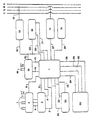
- the figure shows the different units which make part of the device according to the invention, the object supplied with power, here by means of three phase feeding, being formed by a stove, preferably an electrical stove.
- the device according to the invention is driven by power from the same source as the one of the object.
- the device comprises a control unit 1 which here is formed by a micro controller with a computer program adapted to the handling of signals.
- the means, as described above, for effecting the time when the power supply to an object is to be interrupted comprises a timer 2 which picks up an operation time from a block 4 for time setting as a signal is given from the control unit 1 via a conductor 3 to its start-timer-inlet, and counts this period down to zero. Simultaneously with the pick-up of operation time the output of said means are set to zero.
- a signal is given to the control unit via a conduct 5. Furthermore, via another conduct 6, a signal is given to the control unit already when a predetermined time remains of the set period.
- the device determines whether power supply to the object is taking place by means of detecting means which will be further described later. If the device finds that there is no power supply to the object at this occasion, it waits for such a supply to occur and then, as soon as this occurs, interrupts the power supply by means of it's breakers 11. Therefore, the time of use can at minimum be operation time minus a predetermined time, and at maximum be the operation time.
- the setting of the operation time is effected by choosing an on-position or off-position at the three switches 7, which results in eight different combination possibilities.
- One of the possibilities, here in the case when all switches are in their off-position, is that no time is to control the device.
- a signal is given from the time setting block 4 via a conduct 8 to the control unit 1.
- the remaining combination possibilities give different operation times which, via conducts 9, is picked up by the timer.
- the device is also provided with a counting means 10 which effects that the power supply to the object is interrupted by the device as the power supply to the object has been switched on and interrupted a predetermined number of times through the object's own breakers without the timer 2 having been permitted to reach the end of the operation time.
- this counting means is illustrated by the block 10, and is, via a conduct, directly connected to a means 13 for detecting whether the own power supply breakers of the object supplied with power are closed or not. Via conducts 14, 15 this means is also connected to the control unit and can be switched on or off by means of a switch 16 depending on which part of the object that is supplied with power.
- the part supplied with power when the counting means is supposed to be switched on is the oven of a stove.
- the detecting means comprise a unit represented by means of a block 13.
- this unit comprises means for measuring if the current is flowing in the input conducts of the object, these means advantageously being comprised by coils 17 and measuring being done inductively.
- the detecting means are arranged so that only loads exceeding a certain value are registered as load, that is power supply. This is to avoid registering the current flowing to, for example, an oven lamp, a transformer etc. of a stove as load, but only the current that flows to supply hot plates and oven.
- the value preferably is approximately 50 watt.
- the device comprises a means 19 which, during a break of the power supply to the object, measures the time of this break.
- break in the power supply is referred to as a load which goes below the load which the detecting means register as load.
- this means is represented by the block 19 and is connected to the control unit through the conducts 20, 21, and to the output of the detecting means through a conduct 22. It is initiated and reset to zero through a signal at the conduct 21 from the control unit as the latter has obtained a signal from the detecting means that confirms that no load is present.
- this means 19 outputs a signal to the control unit 1 indicating that this is the case.
- the control unit is programmed to bring the means 2 for effecting the time of power supply interruption, here the timer, to once again start from zero, that is from the beginning, at its down counting of the operation time.
- the device comprises means 1, 13, 19 for bringing the means 2 for effecting the time at which the power supply is to be broken to restart its counting from the beginning.
- the preferred embodiment of the device comprises means 23 which, as the power supply to the object has been interrupted by the device, through signalling at the conduct 32 to the control unit and further signalling from the latter, bring the means for detecting whether the object's own breakers are closed or not to execute their detection with a time period between the detecting function occasions which step-wise becomes longer.
- these means comprise the block 23.
- this means 23 preferably through a signal at the conduct 32 to the control unit, controls the breakers of the device, which then are open, by means of signals to close for short periods with a step-wise longer pause between each respective occasion and thereby make it possible for the detecting means to determine whether the object's own breakers are closed.
- This function is initiated when the breakers 11 of the device by any reason, e.g. elapsed operation time, is brought to open by a signal from the control unit, the control unit giving a signal to this means to start its function through a conduct 24.
- the function is interrupted as soon as the detecting means 13 have found the object's own breakers no longer closed and have given a signal to the control unit 1 indicating this, and the control unit has forwarded this information to the means 23 by means of a signal on the conduct 33.
- the means 23 for executing this timer function is preferably arranged in such a way that it effects the maintenance of the time period between the detecting function occasions at a predetermined, maximum value after the step-wise increase of the time period to this value.
- the first pause is preferably approximately 1 second, whereafter the length of the subsequent pauses is step-wise increased by, for example, 1 second at a time until a pause period of approximately 1 minute is obtained, and remains thereafter at this value.
- the block diagram shown comprises also a unit symbolised by a block 25 the principal function of which is to function as an arrangement monitoring the object.
- a block 25 the principal function of which is to function as an arrangement monitoring the object.
- the device according to the invention comprises means 1 which, at a given signal from the above arrangement 25, sees to that the power supply to the object in question is interrupted.
- these means are formed by the control unit which, via a conduct 26, receives such signals and on the basis thereof output signals, via a conduct 27, to the breakers 11 of the device regarding interruption of the power supply to the object.
- a control unit also outputs a signal to the means 23 for creating a step-wise longer time period between the detecting function occasions to initiate its function.
- Such signals from the monitoring arrangement 25 to the device according to the invention are preferably output by the arrangement in case of overheating of, for example, hot plates and/or forming of flames.
- a further signalling taking place between the control unit 1 and the monitoring arrangement 25 refers to the possibility of occasionally deconnecting the means 2 for effecting the time for interruption of the power supply to the object, and said counting means 10, the control unit and the monitoring arrangement thereby constituting means for this function. Therefore, the monitoring arrangement is provided with a member for effecting this function which is manoeuvrable by a user, and when the member is manoeuvred for such a function a signal is transmitted through a conduct 28 from the monitoring arrangement to the control unit.
- the de-connection only applies for one operation period, that is continuos use of the stove with breaks in the use that go below the above mentioned, predetermined time, during which operation period the means 2 for effecting the time for interruption of the power supply to the object is not forced to start its down counting of the operation time from zero. If the control unit obtains a signal from the detecting means with reference to a pause which exceeds said time, the last mentioned means 2 and the counting means 10 will be reconnected.
- the device comprises a means for sending a signal to the monitoring arrangement which indicates that the object is supplied with power.
- this means is constituted by the control unit 1 which, via a conduct 29, outputs a signal to a buzzer arranged in the monitoring arrangement, which buzzer then releases a sound to tell that the object now is supplied with energy, that is turned on.
- the monitoring arrangement is also arranged with a visual means which, during this signalling, is effected to execute a function which makes the operator aware of the object being supplied with energy.
- the visual means may consist of a lamp which is brought to flash at a signal from the device.
- said arrangement is also equipped with a switch for turning the sound of the buzzer off.
- the device in a preferred embodiment, is also provided with means, in the shape of the control unit 1, which at the end of each pause send a signal to the monitoring arrangement which gives rise to a sound from the buzzer, this sound preferably being different from the sound which is released by the buzzer in connection to the turn on of the power supply to the object.
- the device also comprises means for maintaining the device in a power supply interrupting state until a predetermined time has past after its installation or a power supply break of the network supplying the object with power.
- these means comprise the control unit which, when the device has been subjected to lack of power supply, is programmed to transmit a signal via a conduct 27 indicating that the device's own breakers shall be kept open until a predetermined time has past.
- the device according to the preferred embodiment is provided with a visual means 31, preferably a light indicator which at a signal via a conduct 34 from the control unit is activated as the device obtains operational voltage after network voltage or after installation.
- the invention is not in any way restricted to the preferred embodiment described above, but a plurality of possibilities of modifications thereof should be obvious for a man skilled in the art without the embodiments thereby diverging from the scope of the invention as defined by the claims.
- the device according to the invention is constituted by a plurality of discrete components or units in the way shown.
- the same result can be obtained with a system with integrated components.
- the device according to the invention has been exemplified such as applicated to an electric stove, the power supply being referred to as current supply, does not mean that the device is delimited to application at such objects. Naturally, it can find use in a plurality of other contexts, and also where the power supply not necessarily refers to current supply, e.g. at gas stoves.
- effect at which time the power supply is to be interrupted does not only refer to determination of the time for interruption by means of a timer, but that the expression should be understood as “control when the power supply is to be interrupted” and whereby this control then can be effected on a totally other basis than a measure of time, e.g. on the basis of registered overheating of hot plates or on the basis of certain number of on and off switches respectively of the object's own breakers.
Landscapes
- Engineering & Computer Science (AREA)
- Chemical & Material Sciences (AREA)
- Combustion & Propulsion (AREA)
- Mechanical Engineering (AREA)
- General Engineering & Computer Science (AREA)
- Physics & Mathematics (AREA)
- General Physics & Mathematics (AREA)
- Emergency Protection Circuit Devices (AREA)
- Surgical Instruments (AREA)
- Electric Stoves And Ranges (AREA)
- Electrical Discharge Machining, Electrochemical Machining, And Combined Machining (AREA)
- Disintegrating Or Milling (AREA)
- Protection Of Static Devices (AREA)
- Supply And Distribution Of Alternating Current (AREA)
- Electronic Switches (AREA)
- Supplying Of Containers To The Packaging Station (AREA)
- Electric Clocks (AREA)
- Burglar Alarm Systems (AREA)
- Ultra Sonic Daignosis Equipment (AREA)
- Vending Machines For Individual Products (AREA)
- Cookers (AREA)
Claims (11)
- Vorrichtung zum Unterbrechen der Stromversorgung eines Objektes, mitdadurch gekennzeichnet, dass sie Einrichtungen (19) aufweist, die während einer Unterbrechung der Stromversorgung des Objektes die Zeit dieser Unterbrechung messen und nur dann, wenn die Zeit einen vorbestimmten Wert überschreitet, ein Signal zu einer Steuereinheit (1) geben, die ausgelegt ist, dann den Zeitgeber (2) nochmals von 0 bei dem Abwärtszählen der Betriebszeit zu starten.Einrichtungen (1, 2, 11) zum Bestimmen, zu welcher Zeit die Stromversorgung unterbrochen werden soll, wobei diese Einrichtungen einen Zeitgeber (2) aufweisen, mit dem eine gewünschte Betriebszeit des Objektes festgesetzt werden kann,einer Einrichtung (13) zum Ermitteln, ob die eigenen Stromversorgungsschalter des Objektes geschlossen sind oder nicht,Schaltern (11) zum Unterbrechen der Stromversorgung des Objektes und Einrichtungen (1, 11, 13, 23) zum Unterbrochenhalten der Stromversorgung des Objektes, bis die eigenen Schalter des Objektes geöffnet sind,
- Vorrichtung, dadurch gekennzeichnet, dass sie eine Zähleinrichtung (10) aufweist, eine Unterbrechung der Stromversorgung des Objektes die Vorrichtung bewirkt, wenn die Stromversorgung eine vorbestimmte Anzahl von Malen über die eigenen Schalter des Objektes eingeschaltet und ausgeschaltet wurde, ohne dass der Zeitgeber die Möglichkeit hatte, das Ende der Betriebszeit zu erreichen.
- Vorrichtung nach Anspruch 2, dadurch gekennzeichnet, dass die Zähleinrichtung ein- und ausschaltbar ausgebildet ist und eingeschaltet wird in Abhängigkeit davon, welches Teil des Objektes mit Energie versorgt wird.
- Vorrichtung nach einem der Ansprüche 1 bis 3, dadurch gekennzeichnet, dass sie Einrichtungen zum vorherigen Festsetzen der Betriebszeit in dem Zeitgeber aufweist.
- Vorrichtung nach einem der Ansprüche 1 bis 4, dadurch gekennzeichnet, dass sie Einrichtungen (23) aufweist, die dann, wenn die Stromversorgung des Objektes durch die Vorrichtung unterbrochen worden ist, die Einrichtung (13) zum Bestimmen, ob die eigenen Schalter des Objektes geschlossen sind oder nicht, dazu veranlasst, ihre Bestimmungsfunktion zwischen den einzelnen Funktionsbestimmungen mit schrittweiser Zeitspanne auszuführen.
- Vorrichtung nach Anspruch 5, dadurch gekennzeichnet, dass sie Einrichtungen (23) aufweist, das Halten der Zeitspanne zwischen den Funktionsbestimmungen auf einem vorbestimmten maximalen Wert hält, nachdem die Zeitspanne bis auf diesen Wert schrittweise vergrößert wurde.
- Vorrichtung nach einem der vorhergehenden Ansprüche, dadurch gekennzeichnet, dass sie Einrichtungen (1) aufweist, die die Vorrichtung in einem die Stromversorgung unterbrechenden Zustand hält, bis eine vorher festgesetzte Zeitspanne nach der Installation der Vorrichtung oder nach dem Auftreten einer Unterbrechung der Stromversorgung des Netzwerkes vergangen ist, welches die Vorrichtung mit Energie versorgt.
- Vorrichtung nach einem der vorgehenden Ansprüche, dadurch gekennzeichnet, dass sie Einrichtungen (1, 11) aufweist, die auf ein Signal von einer das Objekt überwachenden und der Vorrichtung zugeordneten Anordnung das Unterbrechen der Stromversorgung des Objektes bewirken.
- Vorrichtung nach einem der vorhergehenden Ansprüche, dadurch gekennzeichnet, dass die Vorrichtung ausgelegt ist, um die Stromversorgung eines Herdes zu unterbrechen.
- Vorrichtung nach einem der vorhergehenden Ansprüche, dadurch gekennzeichnet, dass die Energieversorgung eine Stromversorgung ist.
- Vorrichtung nach Anspruch 2 oder 3, dadurch gekennzeichnet, dass die eigenen Schalter des Objektes durch eine Thermostatfunktion gesteuert werden.
Priority Applications (1)
| Application Number | Priority Date | Filing Date | Title |
|---|---|---|---|
| EP03014349A EP1367467A3 (de) | 1994-10-28 | 1995-10-27 | Vorrichtung zur Stromunterbrechnung eines Geräts |
Applications Claiming Priority (3)
| Application Number | Priority Date | Filing Date | Title |
|---|---|---|---|
| SE9403714A SE515225C2 (sv) | 1994-10-28 | 1994-10-28 | Anordning för att bryta energitillförseln till ett objekt |
| SE9403714 | 1994-10-28 | ||
| PCT/SE1995/001273 WO1996013846A1 (en) | 1994-10-28 | 1995-10-27 | A device for interrupting the power supply to an object |
Related Child Applications (1)
| Application Number | Title | Priority Date | Filing Date |
|---|---|---|---|
| EP03014349A Division EP1367467A3 (de) | 1994-10-28 | 1995-10-27 | Vorrichtung zur Stromunterbrechnung eines Geräts |
Publications (2)
| Publication Number | Publication Date |
|---|---|
| EP0801802A1 EP0801802A1 (de) | 1997-10-22 |
| EP0801802B1 true EP0801802B1 (de) | 2003-07-02 |
Family
ID=20395789
Family Applications (2)
| Application Number | Title | Priority Date | Filing Date |
|---|---|---|---|
| EP03014349A Withdrawn EP1367467A3 (de) | 1994-10-28 | 1995-10-27 | Vorrichtung zur Stromunterbrechnung eines Geräts |
| EP95936822A Expired - Lifetime EP0801802B1 (de) | 1994-10-28 | 1995-10-27 | Vorrichtung zum unterbrechen der stromversorgung eines objektes |
Family Applications Before (1)
| Application Number | Title | Priority Date | Filing Date |
|---|---|---|---|
| EP03014349A Withdrawn EP1367467A3 (de) | 1994-10-28 | 1995-10-27 | Vorrichtung zur Stromunterbrechnung eines Geräts |
Country Status (10)
| Country | Link |
|---|---|
| US (1) | US5898237A (de) |
| EP (2) | EP1367467A3 (de) |
| JP (1) | JPH10508145A (de) |
| AT (1) | ATE244452T1 (de) |
| AU (1) | AU3861795A (de) |
| DE (1) | DE69531217D1 (de) |
| FI (1) | FI116599B (de) |
| NO (1) | NO316848B1 (de) |
| SE (1) | SE515225C2 (de) |
| WO (1) | WO1996013846A1 (de) |
Families Citing this family (4)
| Publication number | Priority date | Publication date | Assignee | Title |
|---|---|---|---|---|
| DE10105384A1 (de) * | 2001-02-06 | 2002-08-29 | Peter Becker | Vorrichtung und Verfahren zum Steuern einer elektrischen Energiezuführung |
| DE10114568B4 (de) * | 2001-03-24 | 2008-04-10 | Rainer Sesselmann | Programmgesteuerte Schaltvorrichtung in Netzverbindungen |
| FI117526B3 (fi) | 2005-03-17 | 2016-07-05 | Innohome Oy | Kodinkoneiden ja viihdelaitteiden toimintaa ohjaava ja seuraava lisälaite |
| US20160000251A1 (en) * | 2014-07-03 | 2016-01-07 | Carla Mosley | Stove shut off system |
Family Cites Families (8)
| Publication number | Priority date | Publication date | Assignee | Title |
|---|---|---|---|---|
| DE3044235A1 (de) * | 1980-11-25 | 1982-06-03 | Giovanni Ing.(grad.) 7000 Stuttgart Quinzio | Zusatzschaltgeraet |
| GB2133232B (en) * | 1983-01-04 | 1986-11-12 | Amf Inc | Wall switch timing circuit |
| DE3320128C3 (de) * | 1983-06-03 | 1997-09-11 | Diehl Gmbh & Co | Elektronische Schaltuhr |
| US4782420A (en) * | 1987-06-05 | 1988-11-01 | Holdgaard Jensen Kurt | Safety switch apparatus |
| DE3815984A1 (de) * | 1988-05-10 | 1989-11-23 | Diehl Gmbh & Co | Sicherheitsschaltung fuer einen elektrischen kochherd |
| US5072095A (en) * | 1990-11-29 | 1991-12-10 | Mr. Coffee, Inc. | Vessel warmer utilizing timer reset means responsive to removal of vessel |
| WO1994022065A1 (en) * | 1993-03-19 | 1994-09-29 | Erkki Telamo | Method and apparatus for interrupting current supply to an electric load |
| NO931553L (no) * | 1993-04-29 | 1994-10-31 | Geto Tech Ans | Anordning ved elektrisk krets |
-
1994
- 1994-10-28 SE SE9403714A patent/SE515225C2/sv not_active IP Right Cessation
-
1995
- 1995-10-27 WO PCT/SE1995/001273 patent/WO1996013846A1/en not_active Ceased
- 1995-10-27 DE DE69531217T patent/DE69531217D1/de not_active Expired - Lifetime
- 1995-10-27 EP EP03014349A patent/EP1367467A3/de not_active Withdrawn
- 1995-10-27 JP JP8514497A patent/JPH10508145A/ja not_active Ceased
- 1995-10-27 AU AU38617/95A patent/AU3861795A/en not_active Abandoned
- 1995-10-27 US US08/836,273 patent/US5898237A/en not_active Expired - Lifetime
- 1995-10-27 AT AT95936822T patent/ATE244452T1/de not_active IP Right Cessation
- 1995-10-27 EP EP95936822A patent/EP0801802B1/de not_active Expired - Lifetime
-
1997
- 1997-04-23 FI FI971733A patent/FI116599B/fi not_active IP Right Cessation
- 1997-04-25 NO NO19971927A patent/NO316848B1/no not_active IP Right Cessation
Also Published As
| Publication number | Publication date |
|---|---|
| ATE244452T1 (de) | 2003-07-15 |
| WO1996013846A1 (en) | 1996-05-09 |
| FI116599B (fi) | 2005-12-30 |
| NO971927D0 (no) | 1997-04-25 |
| EP0801802A1 (de) | 1997-10-22 |
| NO971927L (no) | 1997-06-09 |
| AU3861795A (en) | 1996-05-23 |
| EP1367467A3 (de) | 2007-09-19 |
| US5898237A (en) | 1999-04-27 |
| FI971733A0 (fi) | 1997-04-23 |
| JPH10508145A (ja) | 1998-08-04 |
| FI971733L (fi) | 1997-06-11 |
| SE515225C2 (sv) | 2001-07-02 |
| SE9403714D0 (sv) | 1994-10-28 |
| SE9403714L (sv) | 1996-04-29 |
| EP1367467A2 (de) | 2003-12-03 |
| NO316848B1 (no) | 2004-06-01 |
| DE69531217D1 (de) | 2003-08-07 |
Similar Documents
| Publication | Publication Date | Title |
|---|---|---|
| US20080053426A1 (en) | Method for protecting a cooker extractor hood against overheating | |
| AU751113B2 (en) | Combination temperature sensor, warning light sensor and light indicator for heating elements | |
| EP0801802B1 (de) | Vorrichtung zum unterbrechen der stromversorgung eines objektes | |
| US5073701A (en) | Arrangement in a range or a cooking hob | |
| CN102686950B (zh) | 用于提高靠煤气工作的烹饪装置的安全性的方法和系统 | |
| GB2115912A (en) | Instantaneous water heater for shower unit | |
| CA2203803A1 (en) | A device for interrupting the power supply to an object | |
| US20210231305A1 (en) | Indication apparatus to indicate the output level of a pilot flame and method | |
| GB2219152A (en) | Safety timer for electric cooker hotplates | |
| KR101727973B1 (ko) | 인덕션 가열기의 자동소화 장치 | |
| GB2170932A (en) | Status indicators for fuel burning appliances | |
| US4189091A (en) | Furnace having a normally closed blower relay | |
| KR100942500B1 (ko) | 전기매트 또는 전기온수매트 온도조절기의 온도제어 불능시 발열선의 과열을 방지하는 2중 과열방지 회로 | |
| JP3247828B2 (ja) | 電気調理器の加熱制御装置 | |
| JP2002095586A (ja) | 電機調理器の加熱制御装置 | |
| US11089655B1 (en) | Safety circuits for electric heating element | |
| JP2671496B2 (ja) | 油燃焼器の制御装置 | |
| JP3014856U (ja) | 分離型温度調節器における安全装置 | |
| US3116397A (en) | Thermally responsive control device for a surface cooking unit | |
| KR19980028996U (ko) | 전자레인지의 안전장치작동에 따른 미작동 표시장치 | |
| CN109717755A (zh) | 电烹饪炉的安全装置 | |
| GB2201557A (en) | Control for a heating means | |
| JPH05168145A (ja) | 加熱器具の安全装置 | |
| WO2000027011A1 (en) | Control device | |
| JPH08203658A (ja) | 分離型温度調節器における安全装置 |
Legal Events
| Date | Code | Title | Description |
|---|---|---|---|
| PUAI | Public reference made under article 153(3) epc to a published international application that has entered the european phase |
Free format text: ORIGINAL CODE: 0009012 |
|
| 17P | Request for examination filed |
Effective date: 19970506 |
|
| AK | Designated contracting states |
Kind code of ref document: A1 Designated state(s): AT BE CH DE DK ES FR GB GR IE IT LI LU MC NL PT SE |
|
| 17Q | First examination report despatched |
Effective date: 20011016 |
|
| GRAH | Despatch of communication of intention to grant a patent |
Free format text: ORIGINAL CODE: EPIDOS IGRA |
|
| GRAH | Despatch of communication of intention to grant a patent |
Free format text: ORIGINAL CODE: EPIDOS IGRA |
|
| GRAA | (expected) grant |
Free format text: ORIGINAL CODE: 0009210 |
|
| AK | Designated contracting states |
Designated state(s): AT BE CH DE DK ES FR GB GR IE IT LI LU MC NL PT SE |
|
| PG25 | Lapsed in a contracting state [announced via postgrant information from national office to epo] |
Ref country code: NL Free format text: LAPSE BECAUSE OF FAILURE TO SUBMIT A TRANSLATION OF THE DESCRIPTION OR TO PAY THE FEE WITHIN THE PRESCRIBED TIME-LIMIT Effective date: 20030702 Ref country code: LI Free format text: LAPSE BECAUSE OF FAILURE TO SUBMIT A TRANSLATION OF THE DESCRIPTION OR TO PAY THE FEE WITHIN THE PRESCRIBED TIME-LIMIT Effective date: 20030702 Ref country code: IT Free format text: LAPSE BECAUSE OF FAILURE TO SUBMIT A TRANSLATION OF THE DESCRIPTION OR TO PAY THE FEE WITHIN THE PRESCRIBED TIME-LIMIT;WARNING: LAPSES OF ITALIAN PATENTS WITH EFFECTIVE DATE BEFORE 2007 MAY HAVE OCCURRED AT ANY TIME BEFORE 2007. THE CORRECT EFFECTIVE DATE MAY BE DIFFERENT FROM THE ONE RECORDED. Effective date: 20030702 Ref country code: FR Free format text: LAPSE BECAUSE OF FAILURE TO SUBMIT A TRANSLATION OF THE DESCRIPTION OR TO PAY THE FEE WITHIN THE PRESCRIBED TIME-LIMIT Effective date: 20030702 Ref country code: CH Free format text: LAPSE BECAUSE OF FAILURE TO SUBMIT A TRANSLATION OF THE DESCRIPTION OR TO PAY THE FEE WITHIN THE PRESCRIBED TIME-LIMIT Effective date: 20030702 Ref country code: BE Free format text: LAPSE BECAUSE OF FAILURE TO SUBMIT A TRANSLATION OF THE DESCRIPTION OR TO PAY THE FEE WITHIN THE PRESCRIBED TIME-LIMIT Effective date: 20030702 Ref country code: AT Free format text: LAPSE BECAUSE OF FAILURE TO SUBMIT A TRANSLATION OF THE DESCRIPTION OR TO PAY THE FEE WITHIN THE PRESCRIBED TIME-LIMIT Effective date: 20030702 |
|
| REG | Reference to a national code |
Ref country code: GB Ref legal event code: FG4D |
|
| REG | Reference to a national code |
Ref country code: CH Ref legal event code: EP |
|
| REG | Reference to a national code |
Ref country code: IE Ref legal event code: FG4D |
|
| REF | Corresponds to: |
Ref document number: 69531217 Country of ref document: DE Date of ref document: 20030807 Kind code of ref document: P |
|
| PG25 | Lapsed in a contracting state [announced via postgrant information from national office to epo] |
Ref country code: SE Free format text: LAPSE BECAUSE OF FAILURE TO SUBMIT A TRANSLATION OF THE DESCRIPTION OR TO PAY THE FEE WITHIN THE PRESCRIBED TIME-LIMIT Effective date: 20031002 Ref country code: PT Free format text: LAPSE BECAUSE OF FAILURE TO SUBMIT A TRANSLATION OF THE DESCRIPTION OR TO PAY THE FEE WITHIN THE PRESCRIBED TIME-LIMIT Effective date: 20031002 Ref country code: GR Free format text: LAPSE BECAUSE OF FAILURE TO SUBMIT A TRANSLATION OF THE DESCRIPTION OR TO PAY THE FEE WITHIN THE PRESCRIBED TIME-LIMIT Effective date: 20031002 Ref country code: DK Free format text: LAPSE BECAUSE OF FAILURE TO SUBMIT A TRANSLATION OF THE DESCRIPTION OR TO PAY THE FEE WITHIN THE PRESCRIBED TIME-LIMIT Effective date: 20031002 |
|
| PG25 | Lapsed in a contracting state [announced via postgrant information from national office to epo] |
Ref country code: DE Free format text: LAPSE BECAUSE OF FAILURE TO SUBMIT A TRANSLATION OF THE DESCRIPTION OR TO PAY THE FEE WITHIN THE PRESCRIBED TIME-LIMIT Effective date: 20031003 |
|
| PG25 | Lapsed in a contracting state [announced via postgrant information from national office to epo] |
Ref country code: ES Free format text: LAPSE BECAUSE OF FAILURE TO SUBMIT A TRANSLATION OF THE DESCRIPTION OR TO PAY THE FEE WITHIN THE PRESCRIBED TIME-LIMIT Effective date: 20031013 |
|
| PG25 | Lapsed in a contracting state [announced via postgrant information from national office to epo] |
Ref country code: LU Free format text: LAPSE BECAUSE OF NON-PAYMENT OF DUE FEES Effective date: 20031027 Ref country code: GB Free format text: LAPSE BECAUSE OF NON-PAYMENT OF DUE FEES Effective date: 20031027 |
|
| PG25 | Lapsed in a contracting state [announced via postgrant information from national office to epo] |
Ref country code: IE Free format text: LAPSE BECAUSE OF NON-PAYMENT OF DUE FEES Effective date: 20031028 |
|
| PG25 | Lapsed in a contracting state [announced via postgrant information from national office to epo] |
Ref country code: MC Free format text: LAPSE BECAUSE OF NON-PAYMENT OF DUE FEES Effective date: 20031031 |
|
| NLV1 | Nl: lapsed or annulled due to failure to fulfill the requirements of art. 29p and 29m of the patents act | ||
| REG | Reference to a national code |
Ref country code: CH Ref legal event code: PL |
|
| PLBE | No opposition filed within time limit |
Free format text: ORIGINAL CODE: 0009261 |
|
| STAA | Information on the status of an ep patent application or granted ep patent |
Free format text: STATUS: NO OPPOSITION FILED WITHIN TIME LIMIT |
|
| GBPC | Gb: european patent ceased through non-payment of renewal fee |
Effective date: 20031027 |
|
| 26N | No opposition filed |
Effective date: 20040405 |
|
| EN | Fr: translation not filed | ||
| REG | Reference to a national code |
Ref country code: IE Ref legal event code: MM4A |