EP0801833B1 - Regulateur de flux d'energie dans une ligne de transmission avec avancement et retard inegaux de l'angle de phase - Google Patents
Regulateur de flux d'energie dans une ligne de transmission avec avancement et retard inegaux de l'angle de phase Download PDFInfo
- Publication number
- EP0801833B1 EP0801833B1 EP95944638A EP95944638A EP0801833B1 EP 0801833 B1 EP0801833 B1 EP 0801833B1 EP 95944638 A EP95944638 A EP 95944638A EP 95944638 A EP95944638 A EP 95944638A EP 0801833 B1 EP0801833 B1 EP 0801833B1
- Authority
- EP
- European Patent Office
- Prior art keywords
- voltage
- transmission line
- power flow
- alternating
- flow controller
- Prior art date
- Legal status (The legal status is an assumption and is not a legal conclusion. Google has not performed a legal analysis and makes no representation as to the accuracy of the status listed.)
- Expired - Lifetime
Links
Images


Classifications
-
- H—ELECTRICITY
- H02—GENERATION; CONVERSION OR DISTRIBUTION OF ELECTRIC POWER
- H02M—APPARATUS FOR CONVERSION BETWEEN AC AND AC, BETWEEN AC AND DC, OR BETWEEN DC AND DC, AND FOR USE WITH MAINS OR SIMILAR POWER SUPPLY SYSTEMS; CONVERSION OF DC OR AC INPUT POWER INTO SURGE OUTPUT POWER; CONTROL OR REGULATION THEREOF
- H02M1/00—Details of apparatus for conversion
- H02M1/42—Circuits or arrangements for compensating for or adjusting power factor in converters or inverters
- H02M1/4208—Arrangements for improving power factor of AC input
-
- H—ELECTRICITY
- H02—GENERATION; CONVERSION OR DISTRIBUTION OF ELECTRIC POWER
- H02J—ELECTRIC POWER NETWORKS; CIRCUIT ARRANGEMENTS OR SYSTEMS FOR SUPPLYING OR DISTRIBUTING ELECTRIC POWER; SYSTEMS FOR STORING ELECTRIC ENERGY
- H02J3/00—Circuit arrangements for AC mains or AC distribution networks
- H02J3/18—Arrangements for adjusting, eliminating or compensating reactive power in networks
- H02J3/1807—Arrangements for adjusting, eliminating or compensating reactive power in networks using series compensators, e.g. thyristor-controlled series capacitors [TCSC]
- H02J3/1814—Arrangements for adjusting, eliminating or compensating reactive power in networks using series compensators, e.g. thyristor-controlled series capacitors [TCSC] having reactive elements actively controlled by bridge converters, e.g. unified power flow controllers [UPFC] or controlled series voltage compensators
-
- Y—GENERAL TAGGING OF NEW TECHNOLOGICAL DEVELOPMENTS; GENERAL TAGGING OF CROSS-SECTIONAL TECHNOLOGIES SPANNING OVER SEVERAL SECTIONS OF THE IPC; TECHNICAL SUBJECTS COVERED BY FORMER USPC CROSS-REFERENCE ART COLLECTIONS [XRACs] AND DIGESTS
- Y02—TECHNOLOGIES OR APPLICATIONS FOR MITIGATION OR ADAPTATION AGAINST CLIMATE CHANGE
- Y02B—CLIMATE CHANGE MITIGATION TECHNOLOGIES RELATED TO BUILDINGS, e.g. HOUSING, HOUSE APPLIANCES OR RELATED END-USER APPLICATIONS
- Y02B70/00—Technologies for an efficient end-user side electric power management and consumption
- Y02B70/10—Technologies improving the efficiency by using switched-mode power supplies [SMPS], i.e. efficient power electronics conversion e.g. power factor correction or reduction of losses in power supplies or efficient standby modes
-
- Y—GENERAL TAGGING OF NEW TECHNOLOGICAL DEVELOPMENTS; GENERAL TAGGING OF CROSS-SECTIONAL TECHNOLOGIES SPANNING OVER SEVERAL SECTIONS OF THE IPC; TECHNICAL SUBJECTS COVERED BY FORMER USPC CROSS-REFERENCE ART COLLECTIONS [XRACs] AND DIGESTS
- Y02—TECHNOLOGIES OR APPLICATIONS FOR MITIGATION OR ADAPTATION AGAINST CLIMATE CHANGE
- Y02E—REDUCTION OF GREENHOUSE GAS [GHG] EMISSIONS, RELATED TO ENERGY GENERATION, TRANSMISSION OR DISTRIBUTION
- Y02E40/00—Technologies for an efficient electrical power generation, transmission or distribution
- Y02E40/10—Flexible AC transmission systems [FACTS]
Definitions
- This invention relates to apparatus for controlling the flow of power in AC transmission lines, and more particularly to such apparatus providing control of transmission line impedance, transmission line voltage magnitude and/or transmission line voltage phase angle for unequal control of maximum power flow in the two directions in a transmission line including control of power flow in a single direction.
- a generalized power flow controller also referred to as "unified power flow controller” (UPFC) is described in U.S. patent number 5,343,139.
- UPFC unified power flow controller
- This controller injects a voltage with controllable magnitude and angle in series with the transmission line in order to change the effective transmission line voltage, impedance and angle, and thereby control the real and reactive power flow in the line.
- the solid-state inverters of the UPFC are not utilized well because with a given MVA rating they could control the transmission angle over the range of - ⁇ max ⁇ + ⁇ max, i.e.,they could control up to the maximum angular change of 2 ⁇ max, but they are actually used to control the transmission angle over either the positive range of 0 ⁇ ⁇ max or the negative range of ⁇ min ⁇ 0, i.e.,they are used to control up to a maximum angular change of only ⁇ max. Since the required MVA rating is proportional to the control range, it is easy to see that the solid-state inverters of the UPFC are only 50% utilized.
- the bias voltage is in quadrature with the transmission line voltage.
- This can be implemented by a shunt transformer having a three phase delta primary winding connected with the three transmission line phase conductors so that the phase voltages of the secondary windings are in quadrature with the corresponding phase to neutral voltages in the transmission line.
- the coupling means is a transformer having the controllable voltage from the switching power converter means and the bias voltage connected in series to a secondary three phase winding and having the primary winding connected in series with the transmission line.
- a control means controls the controllable magnitude and phase angle of the controllable voltage generated by the switching power converter means to a magnitude and any phase angle relative to the transmission line voltage to selectively adjust, in combination with the bias voltage, individually and in coordination, the effective impedance of the transmission line, the effective transmission line voltage magnitude, and the effective phase angle between voltages at the two ends of the transmission line, within a range set by the bias voltage.
- the control means controls the magnitude of the controllable voltage generated by the switching power converter means to a magnitude no greater than the magnitude of the bias voltage in order to achieve full utilization of the converter in controlling power flow in a single direction.
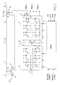
- Figure 1 is a single line schematic diagram of a power flow controller connected to a transmission line in accordance with the invention.
- Figure la is a schematic diagram illustrating a three-phase implementation of the power flow controller of Figure 1.
- Figure 2 is a phasor diagram illustrating the operation of the power flow controller of Figure 1.
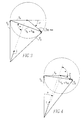
- Figure 3 is a phasor diagram illustrating full series compensation provided by the power flow controller of Figure 1.
- Figure 4 is a phasor diagram illustrating partial series compensation provided by the power flow controller of Figure 1.
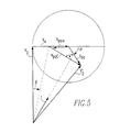
- Figure 5 is a phasor diagram illustrating the general case of angle and impedance control when the power flow controller of Figure 1 provides ⁇ phase shift and series capacitive compensation.
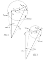
- Figure 6 is a phasor diagram illustrating operation of the power flow controller of Figure 1 when the magnitude of the inverter voltage is greater than the bias voltage.
- Figure 7 is a phasor diagram illustrating operation of the power flow controller of Figure 1 when the magnitude of the controllable convener voltage is less than the magnitude of the bias voltage.
- a power flow controller 1 in accordance with the invention is shown in Figure 1 connected in a transmission line 3 to control the flow of power between a first end 5 and a second end 7 of the transmission line 3. Both the power controller 1 and the transmission line 3 are three-phase but are shown in single line for clarity of illustration.
- the power flow controller 1 includes a switching power converter in the form of preferably a voltage sourced dc to ac inverter 9.
- a switching power converter in the form of preferably a voltage sourced dc to ac inverter 9.
- Such an inverter includes an array of solid state switches such as the gate turn off switches (GTOs) 11, as is well known in the art.
- GTOs gate turn off switches
- the inverter 9 generates at ac terminals 13 a controllable alternating voltage V pq which is injected into the transmission line 3 in series with the transmission line voltage V 0 through a coupling transformer 15. The voltage V pq is thus added to the transmission voltage V 0 to generate an adjusted transmission line voltage V ' 0 .
- the magnitude and phase angle of the injected voltage V pq can be controlled to adjust either singly or in combination the impedance, transmission angle and the magnitude of the voltage on the transmission line 3 for controlling power flow through the transmission line 3.
- a control 17 provides gating signals to the GTOs 11 to control the magnitude and phase of the voltage V pq .
- the control 17 generates the firing signals for the GTOs based upon inputs which include measured variables, parameter settings and reference values for the transmission line voltage V Ref , transmission line impedance Z Ref , the transmission angle ⁇ Ref , and shunt reactive power compensation reference, Q Ref .
- a suitable control is described in patent number 5,343,139.
- the magnitude of the injected voltage V pq is determined by the dc voltage V dc applied to the dc terminals 19 of the inverter 9. If only series reactive compensation is desired, the voltage applied to the dc terminals 19 can be provided by a capacitor 21 as described in U.S. patent number 5,198,746. In such a case, the injected voltage V pq remains in quadrature with the transmission line current I, and hence only reactive power is exchanged with the transmission line by the inverter 9.
- the inverter 9 must also be capable of exchanging real power as well as reactive power with the transmission line.
- Such a mechanism can be a power source or a real impedance as explained in the cross-referenced related application.
- another, preferably voltage sourced, inverter 23 is connected back-to-back with the inverter 9 by a dc link formed by the capacitor 21 connected across the dc terminals 25 of the inverter 23.
- the inverter 23 is connected to the transmission line 3 by a shunt transformer 27 having its primary winding 29 connected in the transmission line 3 and having a first secondary winding 31 connected to the ac terminals 33 of the inverter 23.
- the power flow controller 1 is similar to that described in patent number 5,343,139.
- Such a controller can provide control of full power flow in both directions in the transmission line 3.
- V pq injected voltage
- V pq limits of power flow in the two directions.
- these limits can be set to provide unequal maximum power flow control limits in each direction, and even to limit power flow to a single direction.
- a bias voltage V ⁇ is supplied by a second secondary winding 35 on the shunt transformer 27.
- This bias voltage V ⁇ could be provided by other sources including a separate transformer connected in shunt with the transmission line or a source independent of, but phase locked, to the transmission line 3.
- the bias voltage V ⁇ is vectorially summed with the controllable voltage V pq generated by the inverter 9 to generate a combined voltage which is injected into the transmission line.
- the combined voltage is injected in series with the transmission line voltage by the coupling transformer 15 having its primary winding 39 connected in series with the transmission line 3.
- the secondary winding 41 of the series transformer 15 is connected in series with the ac terminals 13 of the inverter 9 and the secondary winding 35 of the shunt transformer 27.
- FIG. 1A illustrates an exemplary three-phase delta configuration for the windings of the shunt transformer 27 which generates the three-phase quadrature bias voltage V ⁇ a , V ⁇ b , and V ⁇ c in the second secondary windings 35a, 35b and 35c.
- the bias voltage for each phase is vectorially added to the corresponding phase voltage generated by the inverter 9 and injected into the corresponding transmission line phase by the transformers 15a, 15b and 15c.
- the shunt transformer 27 has delta connected primary windings 29a, 29b and 29c, and first secondary windings 31a, 31b and 31c, with the latter connected to the converter 23.
- the total injected voltage, used to control the power flow in the line is made up of two components: Voltage component V ⁇ , which is the fixed quadrature voltage provided by the shunt connected transformer to advance (or retard) the existing transmission angle by a fixed angle ⁇ , and voltage component V pq , which is the controllable component provided by the power flow controller 1.
- the magnitude of V pq is variable in the range of 0 ⁇ V pq ⁇
- (max(
- V' o The magnitude and angle of the controlled transmission voltage V' o is obtained by vectorially adding the total injected voltage V ⁇ + V pq to the existing line voltage V o .
- the proposed power flow controller 1 is also able to provide series compensation to control the line impedance. This is accomplished by choosing the angle ⁇ of voltage V pq so that the injected total voltage ( V ⁇ + V pq ), or a component thereof, is in quadrature with the line current. This is illustrated in Figure 3 for full series compensation and in Figure 4 for partial series compensation combined with ⁇ advancement of the transmission angle.
- V pq ⁇ of V pq is used to cancel part of the fixed quadrature voltage V ⁇
- voltage component V pqC is used to provide series capacitive compensation to reduce the existing reactive line impedance.
- the controllable voltage component that the proposed power flow controller can inject in series with the line is within the boundary defined by a circle drawn with a radius
- the TOTAL voltage injected is the vectorial sum of V pq (which is a phasor with magnitude
- and angle ⁇ in the circle drawn from the center of the circle) and the fixed phasor V ⁇ (which defines the center of the circle), that is, Vinjected V ⁇ + V pq .
Landscapes
- Engineering & Computer Science (AREA)
- Power Engineering (AREA)
- Supply And Distribution Of Alternating Current (AREA)
- Variable-Direction Aerials And Aerial Arrays (AREA)
- Transmitters (AREA)
- Control Of Electrical Variables (AREA)
- Inverter Devices (AREA)
- Ac-Ac Conversion (AREA)
- Cable Transmission Systems, Equalization Of Radio And Reduction Of Echo (AREA)
Claims (17)
- Régulateur (1) de flux d'énergie destiné à réguler le flux d'une énergie électrique circulant entre deux extrémités (5, 7) d'une ligne (3) de transmission de courant alternatif transportant un courant alternatif (I) sous une tension choisie (V0) de ligne de transmission et à une fréquence fondamentale, ledit régulateur comprenant:un moyen convertisseur d'énergie (9) à commutation, générant une tension alternative réglable (Vpq) à ladite fréquence fondamentale dudit courant alternatif (I) dont l'amplitude et l'angle de phase sont réglables par rapport à ladite tension (Vo) de ligne de transmission;un moyen de couplage (15) injectant une tension dans ladite ligne de transmission en série avec ladite tension (Vo) de ligne de transmission; etun moyen de régulation (17) réglant l'amplitude et l'angle de phase réglables de la tension alternative réglable (Vpq) générée par ledit moyen convertisseur d'énergie (9) à commutation à ladite fréquence fondamentale sur une amplitude et un angle de phase (P) par rapport à ladite tension (Vo) de ligne de transmission de manière à ajuster sélectivement l'impédance effective de ladite ligne de transmission, l'angle de phase effectif entre les tensions aux deux extrémités précitées (5, 7) de ladite ligne de transmission (3), ainsi que l'amplitude la tension de ligne de transmission, de manière à réguler le flux d'énergie dans ladite ligne de transmission (3), caractérisé en ce que le régulateur de flux d'énergie comprend en outre un moyen (27) de génération de tension de polarisation générant une tension alternative de polarisation (Va) à ladite fréquence fondamentale dudit courant alternatif (I) et à un angle de phase prédéterminé (P) par rapport à ladite tension (Vo) de ligne transmission, ladite tension alternative de polarisation (Va) ayant une amplitude prédéterminée, et en ce que ledit moyen de couplage (15) fait la somme vectorielle de ladite tension alternative réglable (Vpq) et de ladite tension alternative de polarisation (Va) pour générer une tension combinée (Vpq+ Va), et ladite tension combinée est injectée dans ladite ligne de transmission (3) et l'impédance et l'angle de phase effectifs sont ajustés en combinaison avec ladite tension de polarisation (Va) individuellement et en coordination, de manière à réguler le flux d'énergie dans ladite ligne de transmission (3) entre des limites maximales inégales de régulation de flux d'énergie.
- Régulateur (1) de flux d'énergie selon la revendication 1, dans lequel ledit moyen (27) de génération de tension de polarisation génère ladite tension alternative de polarisation (Vpq) et ledit moyen de régulation (17) règle ladite tension alternative réglable (Vpq) de telle sorte que le flux d'énergie soit déphasé en avance et en retard par ajustement de l'amplitude et de l'angle de phase (ρ) réglables de la tension alternative réglable (Vpq) pour un flux d'énergie dans un seul sens vers une desdites extrémités (5, 7) de ladite ligne de transmission (3).
- Régulateur (1) de flux d'énergie selon la revendication 1. dans lequel ledit moyen (35) de génération de tension de polarisation comprend un moyen générant ladite tension de polarisation (Va) en quadrature avec ladite tension (Vo) de ligne de transmission.
- Régulateur (1) de flux d'énergie selon la revendication 1, dans lequel ledit moyen de couplage (15) comprend un premier transformateur comportant un moyen formant enroulement secondaire (41) auquel ladite tension alternative réglable (Vpq) produite par ledit convertisseur d'énergie (9) à commutation et ladite tension alternative de polarisation (Va) sont appliquées en série, et comportant un enroulement primaire (39) monté en série dans ladite ligne de transmission (3).
- Régulateur (1) de flux d'énergie selon la revendication 4. dans lequel ledit moyen (27) de génération de tension de polarisation comprend un deuxième transformateur monté en parallèle avec ladite ligne de transmission (3).
- Régulateur (1) de flux d'énergie selon la revendication 5. dans lequel ladite ligne de transmission (3) comporte trois conducteurs de phase, ledit moyen convertisseur d'énergie (9) à commutation est un moyen convertisseur triphasé, lesdits premier et deuxième transformateurs (15, 27) sont des transformateurs triphasés, et dans lequel ledit deuxième transformateur (27) est connecté en triangle avec les trois conducteurs de phase précités de la ligne de transmission pour générer une tension de polarisation triphasée (Vαa, Vαb, Vαe) en quadrature avec la tension (Vo) de ligne de transmission.
- Régulateur (1) de flux d'énergie selon la revendication 6, dans lequel ledit moyen convertisseur d'énergie (9) à commutation comprend un convertisseur de courant continu en courant alternatif générant ladite tension alternative réglable (Vpq) et comportant des bornes (13) à courant alternatif connectées audit enroulement secondaire (41) dudit premier transformateur (15), un convertisseur (23) de courant alternatif en courant continu comportant une liaison (21) à courant continu raccordant les bornes (25) dudit convertisseur (23) de courant alternatif en courant continu aux bornes (19) dudit convertisseur (9) de courant continu en courant alternatif pour fournir une puissance active audit convertisseur (9) de courant continu en courant alternatif, et dans lequel ledit deuxième transformateur (27) comporte un deuxième enroulement secondaire triphasé (31a, 31b, 31c) connecté aux bornes (33) à courant alternatif dudit convertisseur (23) de courant alternatif en courant continu.
- Régulateur (1) de flux d'énergie selon la revendication 4, dans lequel ledit moyen (27) de génération de tension de polarisation génère ladite tension alternative de polarisation (Vα) et ledit moyen de régulation (17) règle ladite tension alternative réglable (Vpq) de telle sorte que le flux d'énergie augmente et diminue par ajustement de l'amplitude et de l'angle de phase réglables de la tension alternative réglable (Vpq) pour un flux d'énergie dans un seul sens vers une desdites extrémités (5, 7) de ladite ligne de transmission (3).
- Régulateur (1) de flux d'énergie selon la revendication 1, dans lequel ledit moyen convertisseur d'énergie (9) à commutation comprend un convertisseur de courant continu en courant alternatif générant ladite tension alternative réglable (Vpq) et un moyen de puissance en courant continu (23) connecté aux bornes (19) dudit convertisseur (9) de courant continu en courant alternatif pour fournir une puissance active audit convertisseur (9) de courant continu en courant alternatif.
- Régulateur (1) de flux d'énergie selon la revendication 9, dans lequel ledit moyen de puissance en courant continu comprend un convertisseur de courant alternatif en courant continu comportant un moyen formant liaison (21) à courant continu, connecté auxdites bornes (19) à courant continu dudit convertisseur (9) de courant continu en courant alternatif et un moyen formant transformateur shunt (27) comportant un enroulement primaire (29) connecté en parallèle avec ladite ligne de transmission (3), comportant un premier enroulement secondaire (35) formant ledit moyen de génération de tension de polarisation et comportant une deuxième enroulement secondaire (31) connecté aux bornes (33) à courant alternatif dudit convertisseur (23) de courant alternatif en courant continu.
- Régulateur (1) de flux d'énergie selon la revendication 1, dans lequel ledit moyen (27) de génération de tension de polarisation comprend un transformateur en parallèle comportant un enroulement primaire (29) monté en parallèle avec ladite ligne de transmission et un enroulement secondaire (35) fournissant ladite tension alternative de polarisation (Vα).
- Régulateur (1) de flux d'énergie selon la revendication 11, dans lequel ledit moyen convertisseur d'énergie (9) à commutation présente des limites maximales choisies de tensions positive et négative et ledit moyen de régulation (17) règle ladite amplitude réglable de la tension alternative réglable (Vpq) entre lesdites limites de tensions positive et négative et dans lequel ladite limite de tension négative n'est pas supérieure à ladite amplitude prédéterminée de ladite tension alternative de polarisation (Vα).
- Régulateur (1) de flux d'énergie selon la revendication 11 dans lequel ledit transformateur shunt (27) est monté de manière à générer ladite tension alternative de polarisation (Vα) en quadrature avec ladite tension (Vo) de ligne de transmission.
- Régulateur (1) de flux d'énergie selon la revendication 13, dans lequel ladite ligne de transmission (3) et ledit transformateur shunt (27) sont triphasés, et dans lequel ledit transformateur shunt (27) est monté en triangle pour générer une tension de polarisation alternative triphasée (Vαa, Vαb, Vαc) en quadrature avec ladite tension V0 de ligne de transmission.
- Régulateur (1) de flux d'énergie selon la revendication 1, dans lequel ladite tension alternative de polarisation (Vα) est générée en quadrature avec ladite tension (Vo) de ligne de transmission et à une amplitude prédéterminée, le régulateur de flux d'énergie comprenant, en outre, un moyen (23) fournissant une puissance active audit moyen formant convertisseur d'énergie à commutation et audit moyen de commande (17) commandant l'échange de puissance active et réactive entre ladite ligne de transmission (3) et ledit moyen convertisseur d'énergie (9) à commutation par réglage de ladite tension alternative réglable (Vpq) sur une amplitude choisie qui n'est pas supérieure à ladite amplitude prédéterminée de ladite tension alternative de polarisation (Vα) et sur un angle de phase choisi (ρ)compris entre 0° et 360° pour établir une impédance de ligne de transmission choisie , un angle de transmission choisi, et une tension de ligne de transmission choisie afin de réguler le flux d'énergie à travers ladite ligne de transmission (3) dans un seul sens.
- Régulateur (1) de flux d'énergie selon la revendication 15, dans lequel ledit moyen (27) de génération de tension de polarisation comprend un transformateur shunt monté en parallèle avec ladite ligne de transmission (3).
- Régulateur (1) de flux d'énergie selon la revendication 16. dans lequel ledit moyen de couplage (15) comprend un transformateur série comportant un enroulement secondaire (41) auquel sont appliquées en série ladite tension alternative réglable (Vpq) et ladite tension alternative de polarisation (Vα), et un enroulement primaire (39) monté en série avec ladite ligne de transmission (3).
Applications Claiming Priority (3)
| Application Number | Priority Date | Filing Date | Title |
|---|---|---|---|
| US08/368,947 US5469044A (en) | 1995-01-05 | 1995-01-05 | Transmission line power flow controller with unequal advancement and retardation of transmission angle |
| US368947 | 1995-01-05 | ||
| PCT/US1995/016670 WO1996021262A1 (fr) | 1995-01-05 | 1995-12-13 | Regulateur de flux d'energie dans une ligne de transmission avec avancement et retard inegaux de l'angle de phase |
Publications (3)
| Publication Number | Publication Date |
|---|---|
| EP0801833A1 EP0801833A1 (fr) | 1997-10-22 |
| EP0801833B1 true EP0801833B1 (fr) | 1999-06-30 |
| EP0801833B2 EP0801833B2 (fr) | 2007-03-07 |
Family
ID=23453417
Family Applications (1)
| Application Number | Title | Priority Date | Filing Date |
|---|---|---|---|
| EP95944638A Expired - Lifetime EP0801833B2 (fr) | 1995-01-05 | 1995-12-13 | Regulateur de flux d'energie dans une ligne de transmission avec avancement et retard inegaux de l'angle de phase |
Country Status (11)
| Country | Link |
|---|---|
| US (1) | US5469044A (fr) |
| EP (1) | EP0801833B2 (fr) |
| JP (1) | JP3759613B2 (fr) |
| KR (1) | KR100390885B1 (fr) |
| CN (1) | CN1062684C (fr) |
| AT (1) | ATE181788T1 (fr) |
| AU (1) | AU4741296A (fr) |
| CA (1) | CA2209312A1 (fr) |
| DE (1) | DE69510564T3 (fr) |
| WO (1) | WO1996021262A1 (fr) |
| ZA (1) | ZA9632B (fr) |
Cited By (1)
| Publication number | Priority date | Publication date | Assignee | Title |
|---|---|---|---|---|
| CN106786607A (zh) * | 2017-03-17 | 2017-05-31 | 国网江苏省电力公司 | 一种确定upfc工程安装位置和安装容量的方法 |
Families Citing this family (69)
| Publication number | Priority date | Publication date | Assignee | Title |
|---|---|---|---|---|
| US5610501A (en) * | 1995-02-01 | 1997-03-11 | Westinghouse Electric Corporation | Dynamic power and voltage regulator for an ac transmission line |
| EP0740387B1 (fr) | 1995-04-21 | 2002-06-12 | General Electric Company | Système d'interconnexion pour la transmission de puissance entre systèmes électriques |
| US5841267A (en) * | 1995-04-21 | 1998-11-24 | General Electric Co. | Power flow control with rotary transformers |
| US5952816A (en) * | 1995-04-21 | 1999-09-14 | General Electric Co. | Compensation for power transfer systems using variable rotary transformer |
| US5953225A (en) * | 1995-04-21 | 1999-09-14 | General Electric Co. | Power flow control and power recovery with rotary transformers |
| US5734256A (en) * | 1995-05-31 | 1998-03-31 | General Electric Company | Apparatus for protection of power-electronics in series compensating systems |
| US6021035A (en) * | 1995-05-31 | 2000-02-01 | General Electric Company | Apparatus for protection of power-electronics in series compensating systems |
| US5594630A (en) * | 1995-06-27 | 1997-01-14 | Sundstrand Corporation | Add-on distortion scrubber for AC power systems |
| US5698969A (en) * | 1995-11-29 | 1997-12-16 | Westinghouse Electric Corporation | Apparatus and method for interline power flow control |
| SE505745C2 (sv) * | 1996-01-18 | 1997-10-06 | Asea Brown Boveri | Anordning för styrning av en regulatorutrustning för dämpning av effektsvängningar i en kraftlinje |
| US5818126A (en) * | 1996-10-02 | 1998-10-06 | Regents Of The University Of Minnesota | Power transfer controller |
| US5754035A (en) * | 1997-01-14 | 1998-05-19 | Westinghouse Electric Corporation | Apparatus and method for controlling flow of power in a transmission line including stable reversal of power flow |
| US5808452A (en) * | 1997-09-15 | 1998-09-15 | Gyugyi; Laszlo | Power flow controller with dc-to-dc converter linking shunt and series connected inverters |
| US5984173A (en) * | 1998-02-02 | 1999-11-16 | Siemens Power Transmission & Distribution, Llc | Neutral point connected apparatus providing compensation to an AC power line |
| WO1999045623A1 (fr) * | 1998-03-03 | 1999-09-10 | Siemens Westinghouse Power Corporation | Dispositif permettant d'agir sur le flux de puissance d'une ligne de transmission, y compris une inversion stable de ce flux et technique afferente |
| US5949221A (en) * | 1998-05-21 | 1999-09-07 | Siemens Westinghouse Power Corporation | Line powered, primary side connected apparatus injecting voltage compensation into an electric power line using one transformer |
| US6011381A (en) * | 1998-11-02 | 2000-01-04 | American Electric Power Service Corporation | Three-phase auto transformer with two tap changers for ratio and phase-angle control |
| AU760758B2 (en) * | 1999-09-13 | 2003-05-22 | Aloys Wobben | Method for controlling the reactive power and device for generating electrical energy in an electrical network |
| US6144191A (en) * | 2000-02-18 | 2000-11-07 | Utility Systems Technologies, Inc. | Voltage regulator |
| CA2351895C (fr) | 2000-06-30 | 2009-12-15 | General Electric Company | Ensemble de fixation de bague collectrice pour barre haute puissance de frottement de courant triphase |
| US6469414B2 (en) | 2000-06-30 | 2002-10-22 | General Electric Company | Slip-ring mounting assembly for high-power rotary current collector system |
| US6456021B1 (en) | 2000-06-30 | 2002-09-24 | General Electric Company | Rotating variable frequency transformer with high voltage cables |
| US6465926B2 (en) | 2000-06-30 | 2002-10-15 | General Electric Company | Cleaning/cooling of high-power rotary current collector system |
| EP1344308A1 (fr) * | 2000-12-22 | 2003-09-17 | Bowman Power Systems Limited | Systeme de commande de forme d'onde |
| JP4118531B2 (ja) * | 2001-05-10 | 2008-07-16 | 株式会社東芝 | 電力調整装置 |
| RU2216097C2 (ru) * | 2001-08-15 | 2003-11-10 | Кубанский государственный аграрный университет | Устройство для стабилизации частоты и напряжения автономного асинхронного генератора |
| RU2281524C2 (ru) * | 2002-08-27 | 2006-08-10 | Кубанский государственный аграрный университет | Электрифицированный стенд для исследования электрических машин |
| CN1682420A (zh) * | 2002-09-09 | 2005-10-12 | 美国超导体公司 | 具有功率流控制器的低阻抗输电线 |
| US6737837B1 (en) * | 2002-11-25 | 2004-05-18 | Abb Ab | Device and a method for control of power flow in a transmission line |
| US7117070B2 (en) * | 2003-06-30 | 2006-10-03 | Rensselaer Polytechnic Institute | Power flow controller responsive to power circulation demand for optimizing power transfer |
| US7105952B2 (en) * | 2003-10-03 | 2006-09-12 | Soft Switching Technologies Corporation | Distributed floating series active impendances for power transmission systems |
| CN101010848B (zh) * | 2004-08-27 | 2010-04-28 | Abb研究有限公司 | 控制高电压网络中的功率流的方法和设备 |
| SE527686C2 (sv) * | 2004-10-29 | 2006-05-09 | Abb Research Ltd | Styrning av elektriskt effektflöde |
| CN101080861B (zh) * | 2004-12-16 | 2012-05-30 | Abb研究有限公司 | 用于控制高电压网络中的电功率流的设备和方法 |
| CN101390267B (zh) * | 2006-02-23 | 2011-08-10 | Abb研究有限公司 | 输电线路中的电力潮流的控制 |
| RU2393608C2 (ru) * | 2006-03-28 | 2010-06-27 | Абб Рисёч Лтд | Устройство и способ управления потоком мощности в линии электропередачи |
| KR100776352B1 (ko) * | 2006-04-25 | 2007-11-15 | 한국전력공사 | Scada와 연계한 upfc의 자동운전 시스템 및 그방법 |
| KR100827571B1 (ko) * | 2006-10-31 | 2008-05-07 | 한국전력공사 | Scada 온라인 facts 시뮬레이터 시스템 |
| WO2008081049A1 (fr) * | 2006-12-28 | 2008-07-10 | Wind To Power System, S.L. | Générateur asynchrone avec régulation de la tension appliquée sur le stator |
| CN101291057B (zh) * | 2007-04-20 | 2010-05-19 | 上海输配电股份有限公司 | 采用三单相结构的动态电压补偿器 |
| US7701870B2 (en) * | 2007-12-28 | 2010-04-20 | United States Cellular Corporation | Zero rating in wireless prepaid communications network |
| US20100090789A1 (en) * | 2008-10-14 | 2010-04-15 | Middle Atlantic Products, Inc. | Method, system and transformer for mitigating harmonics |
| US8179104B2 (en) * | 2009-11-06 | 2012-05-15 | Siemens Energy, Inc. | Automatic self-adjusting voltage controller |
| US9634490B2 (en) * | 2011-02-08 | 2017-04-25 | General Electric Company | Dynamic voltage restoration system and method |
| WO2012128660A1 (fr) * | 2011-03-21 | 2012-09-27 | Открытое Акционерное Общество "Федеральная Сетевая Компания Единой Энергетической Системы" (Оао "Фск Еэс") | PROCÉDÉ DE COMMANDE RAPIDE DE TRANSFERT DE PUISSANCE ACTIVE ET FRAGMENT D'UN SYSTÈME INTELLIGENT DE GESTION D'ÉNERGIE ÉLECTRIQUE POUR LE METTRE EN œUVRE |
| US9281756B2 (en) * | 2011-11-11 | 2016-03-08 | Varentec, Inc. | Power flow controller with a fractionally rated back-to-back converter |
| DE102011122580B4 (de) | 2011-12-29 | 2022-10-13 | Bob Holding Gmbh | Verfahren zum Betreiben eines elektrischen Versorgungsnetzes und zugehörige Steuereinheit |
| WO2013126660A2 (fr) | 2012-02-24 | 2013-08-29 | Board Of Trustees Of Michigan State University | Régulateur de flux d'énergie unifié sans transformateur |
| CN102638170B (zh) * | 2012-04-10 | 2014-12-10 | 四川大学 | 恒幅矢量交流调压方法 |
| CN102638171A (zh) * | 2012-04-10 | 2012-08-15 | 四川大学 | 一种无隔离恒幅矢量交流调压器 |
| US9042129B2 (en) * | 2012-11-15 | 2015-05-26 | General Electric Company | System and method for controlling power in a distribution system |
| CN104348171A (zh) * | 2013-08-05 | 2015-02-11 | 青岛菲特电器科技有限公司 | 一种超高压线路并联可控电抗器 |
| CN103955141B (zh) * | 2014-05-09 | 2017-12-26 | 国家电网公司 | 一种统一潮流控制器低压物理模型的试验电路及试验方法 |
| JP6363391B2 (ja) * | 2014-05-16 | 2018-07-25 | 株式会社東芝 | 電圧調整装置 |
| US9401636B2 (en) | 2014-05-28 | 2016-07-26 | Gridco Inc. | Multi-function power regulator for prioritizing functions and allocating resources thereof |
| US10180696B2 (en) | 2015-12-08 | 2019-01-15 | Smart Wires Inc. | Distributed impedance injection module for mitigation of the Ferranti effect |
| US10903653B2 (en) | 2015-12-08 | 2021-01-26 | Smart Wires Inc. | Voltage agnostic power reactor |
| US10418814B2 (en) * | 2015-12-08 | 2019-09-17 | Smart Wires Inc. | Transformers with multi-turn primary windings for dynamic power flow control |
| US10008317B2 (en) | 2015-12-08 | 2018-06-26 | Smart Wires Inc. | Voltage or impedance-injection method using transformers with multiple secondary windings for dynamic power flow control |
| US10199150B2 (en) | 2015-12-10 | 2019-02-05 | Smart Wires Inc. | Power transmission tower mounted series injection transformer |
| US10218175B2 (en) | 2016-02-11 | 2019-02-26 | Smart Wires Inc. | Dynamic and integrated control of total power system using distributed impedance injection modules and actuator devices within and at the edge of the power grid |
| US10097037B2 (en) | 2016-02-11 | 2018-10-09 | Smart Wires Inc. | System and method for distributed grid control with sub-cyclic local response capability |
| US10651633B2 (en) | 2016-04-22 | 2020-05-12 | Smart Wires Inc. | Modular, space-efficient structures mounting multiple electrical devices |
| US10468880B2 (en) | 2016-11-15 | 2019-11-05 | Smart Wires Inc. | Systems and methods for voltage regulation using split-conductors with loop current reduction |
| US10666038B2 (en) | 2017-06-30 | 2020-05-26 | Smart Wires Inc. | Modular FACTS devices with external fault current protection |
| CN109038606B (zh) * | 2018-08-08 | 2024-04-02 | 全球能源互联网研究院有限公司 | 一种有载调压变压器及统一潮流控制系统 |
| CN109470990B (zh) * | 2018-10-25 | 2020-12-18 | 南京南瑞继保电气有限公司 | 一种适应upfc接入的线路变化量故障方向判断方法和装置 |
| CN109193682B (zh) * | 2018-11-14 | 2021-06-11 | 燕山大学 | 基于pac的upqc无缝切换功率协调控制策略 |
| EP4687249A1 (fr) | 2024-08-02 | 2026-02-04 | Efacec Energia - Máquinas e Equipamentos Eléctricos S.A. | Régulateur de tension dynamique pour réseau basse tension et procédés respectifs de démarrage et d'arrêt |
Family Cites Families (12)
| Publication number | Priority date | Publication date | Assignee | Title |
|---|---|---|---|---|
| US3942032A (en) † | 1974-02-15 | 1976-03-02 | Casazza John A | Power injector control means for transmission networks |
| JPS5931286B2 (ja) * | 1978-10-11 | 1984-08-01 | 関西電力株式会社 | 系統連系方法 |
| EP0053413B1 (fr) † | 1980-12-03 | 1984-10-24 | BBC Aktiengesellschaft Brown, Boveri & Cie. | Dispositif pour la commande continue de l'angle de phase dans des installations de transmission d'énergie électrique |
| US4651265A (en) * | 1985-07-29 | 1987-03-17 | Westinghouse Electric Corp. | Active power conditioner system |
| JPH0783615B2 (ja) * | 1988-11-28 | 1995-09-06 | 三菱電機株式会社 | 三相変換器 |
| US5166597A (en) * | 1991-08-08 | 1992-11-24 | Electric Power Research Institute | Phase-shifting transformer system |
| US5198746A (en) * | 1991-09-16 | 1993-03-30 | Westinghouse Electric Corp. | Transmission line dynamic impedance compensation system |
| US5343139A (en) * | 1992-01-31 | 1994-08-30 | Westinghouse Electric Corporation | Generalized fast, power flow controller |
| US5321598A (en) * | 1992-09-18 | 1994-06-14 | Westinghouse Electric Corp. | Three-phase active filter utilizing rotating axis transformation |
| US5355294A (en) * | 1992-11-25 | 1994-10-11 | General Electric Company | Unity power factor control for dual active bridge converter |
| US5329222A (en) * | 1992-11-30 | 1994-07-12 | Westinghouse Electric Corporation | Apparatus and method for dynamic voltage restoration of utility distribution networks |
| US5355295A (en) * | 1993-08-19 | 1994-10-11 | Westinghouse Electric Corporation | Series-parallel active power line conditioner utilizing temporary link energy boosting for enhanced peak voltage regulation capability |
-
1995
- 1995-01-05 US US08/368,947 patent/US5469044A/en not_active Expired - Lifetime
- 1995-12-13 JP JP52107896A patent/JP3759613B2/ja not_active Expired - Lifetime
- 1995-12-13 KR KR1019970704592A patent/KR100390885B1/ko not_active Expired - Lifetime
- 1995-12-13 AT AT95944638T patent/ATE181788T1/de not_active IP Right Cessation
- 1995-12-13 DE DE69510564T patent/DE69510564T3/de not_active Expired - Lifetime
- 1995-12-13 AU AU47412/96A patent/AU4741296A/en not_active Abandoned
- 1995-12-13 WO PCT/US1995/016670 patent/WO1996021262A1/fr not_active Ceased
- 1995-12-13 EP EP95944638A patent/EP0801833B2/fr not_active Expired - Lifetime
- 1995-12-13 CN CN95197270A patent/CN1062684C/zh not_active Expired - Fee Related
- 1995-12-13 CA CA002209312A patent/CA2209312A1/fr not_active Abandoned
-
1996
- 1996-01-03 ZA ZA9632A patent/ZA9632B/xx unknown
Cited By (2)
| Publication number | Priority date | Publication date | Assignee | Title |
|---|---|---|---|---|
| CN106786607A (zh) * | 2017-03-17 | 2017-05-31 | 国网江苏省电力公司 | 一种确定upfc工程安装位置和安装容量的方法 |
| CN106786607B (zh) * | 2017-03-17 | 2019-04-09 | 国网江苏省电力公司 | 一种确定upfc工程安装位置和安装容量的方法 |
Also Published As
| Publication number | Publication date |
|---|---|
| CN1062684C (zh) | 2001-02-28 |
| US5469044A (en) | 1995-11-21 |
| ZA9632B (en) | 1996-07-10 |
| CN1171863A (zh) | 1998-01-28 |
| JP3759613B2 (ja) | 2006-03-29 |
| WO1996021262A1 (fr) | 1996-07-11 |
| EP0801833B2 (fr) | 2007-03-07 |
| CA2209312A1 (fr) | 1996-07-11 |
| ATE181788T1 (de) | 1999-07-15 |
| DE69510564T3 (de) | 2007-08-16 |
| KR100390885B1 (ko) | 2003-10-22 |
| JPH10511839A (ja) | 1998-11-10 |
| EP0801833A1 (fr) | 1997-10-22 |
| DE69510564T2 (de) | 1999-10-21 |
| DE69510564D1 (de) | 1999-08-05 |
| AU4741296A (en) | 1996-07-24 |
Similar Documents
| Publication | Publication Date | Title |
|---|---|---|
| EP0801833B1 (fr) | Regulateur de flux d'energie dans une ligne de transmission avec avancement et retard inegaux de l'angle de phase | |
| Fujita et al. | Dynamic control and performance of a unified power flow controller for stabilizing an AC transmission system | |
| CA2195085C (fr) | Regulateur d'une ligne de transmission comprenant une source de tension commandee en continu, sensible a une demande en puissance active ainsi qu'a une demande en puissance reactive | |
| US6335613B1 (en) | Versatile power flow transformers for compensating power flow in a transmission line | |
| US5698969A (en) | Apparatus and method for interline power flow control | |
| CN100474730C (zh) | 用于控制输电线中功率潮流的装置和方法 | |
| US5610501A (en) | Dynamic power and voltage regulator for an ac transmission line | |
| US5754035A (en) | Apparatus and method for controlling flow of power in a transmission line including stable reversal of power flow | |
| US6025701A (en) | Static and dynamic mains voltage support by a static power factor correction device having a self-commutated converter | |
| US5814975A (en) | Inverter controlled series compensator | |
| PL180944B1 (pl) | Sposób i urządzenie przełączające do nastawiania przekładni zwojowej transformatora | |
| US5375053A (en) | Controlled power supply | |
| US6841976B1 (en) | Multi-line power flow transformer for compensating power flow among transmission lines | |
| Taheri et al. | Application of synchronous static series compensator (SSSC) on enhancement of voltage stability and power oscillation damping | |
| EP0698309B1 (fr) | Appareil de dephasage de tensions pour interconnecter deux reseaux synchrones polyphases a courant alternatif | |
| US6396248B1 (en) | Versatile power flow transformers for compensating power flow in a transmission line | |
| US6384581B1 (en) | Versatile power flow transformers for compensating power flow in a transmission line | |
| JP2005510076A (ja) | 制御可能なインピーダンスを有するデバイス | |
| US6420856B1 (en) | Versatile power flow transformers for compensating power flow in a transmission line | |
| Zhou et al. | The impact of STATCOM on distance relay | |
| RU2027278C1 (ru) | Трехфазный компенсатор реактивной мощности | |
| US4001670A (en) | Static reactive power generating apparatus | |
| JPH10504177A (ja) | 普及型高速電力潮流コントローラ | |
| Fujita et al. | Transient analysis of a unified power flow controller, and its application to design of the DC-link capacitor | |
| Fujita et al. | Dynamic performance of a unified power flow controller for stabilizing AC transmission systems |
Legal Events
| Date | Code | Title | Description |
|---|---|---|---|
| PUAI | Public reference made under article 153(3) epc to a published international application that has entered the european phase |
Free format text: ORIGINAL CODE: 0009012 |
|
| 17P | Request for examination filed |
Effective date: 19970701 |
|
| AK | Designated contracting states |
Kind code of ref document: A1 Designated state(s): AT BE CH DE DK ES FR GB GR IE IT LI LU MC NL PT SE |
|
| RIN1 | Information on inventor provided before grant (corrected) |
Inventor name: GYUGYI, LASZLO Inventor name: NELSON, ROBERT, J. |
|
| 17Q | First examination report despatched |
Effective date: 19971105 |
|
| GRAG | Despatch of communication of intention to grant |
Free format text: ORIGINAL CODE: EPIDOS AGRA |
|
| GRAG | Despatch of communication of intention to grant |
Free format text: ORIGINAL CODE: EPIDOS AGRA |
|
| GRAH | Despatch of communication of intention to grant a patent |
Free format text: ORIGINAL CODE: EPIDOS IGRA |
|
| GRAH | Despatch of communication of intention to grant a patent |
Free format text: ORIGINAL CODE: EPIDOS IGRA |
|
| GRAA | (expected) grant |
Free format text: ORIGINAL CODE: 0009210 |
|
| RAP1 | Party data changed (applicant data changed or rights of an application transferred) |
Owner name: SIEMENS WESTINGHOUSE POWER CORPORATION |
|
| AK | Designated contracting states |
Kind code of ref document: B1 Designated state(s): AT BE CH DE DK ES FR GB GR IE IT LI LU MC NL PT SE |
|
| PG25 | Lapsed in a contracting state [announced via postgrant information from national office to epo] |
Ref country code: NL Free format text: LAPSE BECAUSE OF FAILURE TO SUBMIT A TRANSLATION OF THE DESCRIPTION OR TO PAY THE FEE WITHIN THE PRESCRIBED TIME-LIMIT Effective date: 19990630 Ref country code: GR Free format text: LAPSE BECAUSE OF NON-PAYMENT OF DUE FEES Effective date: 19990630 Ref country code: ES Free format text: THE PATENT HAS BEEN ANNULLED BY A DECISION OF A NATIONAL AUTHORITY Effective date: 19990630 Ref country code: BE Free format text: LAPSE BECAUSE OF FAILURE TO SUBMIT A TRANSLATION OF THE DESCRIPTION OR TO PAY THE FEE WITHIN THE PRESCRIBED TIME-LIMIT Effective date: 19990630 Ref country code: AT Free format text: LAPSE BECAUSE OF FAILURE TO SUBMIT A TRANSLATION OF THE DESCRIPTION OR TO PAY THE FEE WITHIN THE PRESCRIBED TIME-LIMIT Effective date: 19990630 |
|
| REF | Corresponds to: |
Ref document number: 181788 Country of ref document: AT Date of ref document: 19990715 Kind code of ref document: T |
|
| REG | Reference to a national code |
Ref country code: CH Ref legal event code: EP |
|
| REF | Corresponds to: |
Ref document number: 69510564 Country of ref document: DE Date of ref document: 19990805 |
|
| REG | Reference to a national code |
Ref country code: CH Ref legal event code: NV Representative=s name: SIEMENS SCHWEIZ AG |
|
| REG | Reference to a national code |
Ref country code: IE Ref legal event code: FG4D |
|
| ITF | It: translation for a ep patent filed | ||
| PG25 | Lapsed in a contracting state [announced via postgrant information from national office to epo] |
Ref country code: PT Free format text: LAPSE BECAUSE OF FAILURE TO SUBMIT A TRANSLATION OF THE DESCRIPTION OR TO PAY THE FEE WITHIN THE PRESCRIBED TIME-LIMIT Effective date: 19990930 Ref country code: DK Free format text: LAPSE BECAUSE OF FAILURE TO SUBMIT A TRANSLATION OF THE DESCRIPTION OR TO PAY THE FEE WITHIN THE PRESCRIBED TIME-LIMIT Effective date: 19990930 |
|
| ET | Fr: translation filed | ||
| NLV1 | Nl: lapsed or annulled due to failure to fulfill the requirements of art. 29p and 29m of the patents act | ||
| PG25 | Lapsed in a contracting state [announced via postgrant information from national office to epo] |
Ref country code: LU Free format text: LAPSE BECAUSE OF NON-PAYMENT OF DUE FEES Effective date: 19991213 Ref country code: IE Free format text: LAPSE BECAUSE OF NON-PAYMENT OF DUE FEES Effective date: 19991213 Ref country code: GB Free format text: LAPSE BECAUSE OF NON-PAYMENT OF DUE FEES Effective date: 19991213 |
|
| PGFP | Annual fee paid to national office [announced via postgrant information from national office to epo] |
Ref country code: SE Payment date: 19991217 Year of fee payment: 5 |
|
| PGFP | Annual fee paid to national office [announced via postgrant information from national office to epo] |
Ref country code: CH Payment date: 20000317 Year of fee payment: 5 |
|
| PLBQ | Unpublished change to opponent data |
Free format text: ORIGINAL CODE: EPIDOS OPPO |
|
| PLBI | Opposition filed |
Free format text: ORIGINAL CODE: 0009260 |
|
| PLBF | Reply of patent proprietor to notice(s) of opposition |
Free format text: ORIGINAL CODE: EPIDOS OBSO |
|
| 26 | Opposition filed |
Opponent name: ABB AB Effective date: 20000330 |
|
| PG25 | Lapsed in a contracting state [announced via postgrant information from national office to epo] |
Ref country code: MC Free format text: LAPSE BECAUSE OF NON-PAYMENT OF DUE FEES Effective date: 20000630 |
|
| GBPC | Gb: european patent ceased through non-payment of renewal fee |
Effective date: 19991213 |
|
| PLBF | Reply of patent proprietor to notice(s) of opposition |
Free format text: ORIGINAL CODE: EPIDOS OBSO |
|
| REG | Reference to a national code |
Ref country code: IE Ref legal event code: MM4A |
|
| PLBF | Reply of patent proprietor to notice(s) of opposition |
Free format text: ORIGINAL CODE: EPIDOS OBSO |
|
| PG25 | Lapsed in a contracting state [announced via postgrant information from national office to epo] |
Ref country code: SE Free format text: LAPSE BECAUSE OF NON-PAYMENT OF DUE FEES Effective date: 20001214 |
|
| PG25 | Lapsed in a contracting state [announced via postgrant information from national office to epo] |
Ref country code: LI Free format text: LAPSE BECAUSE OF NON-PAYMENT OF DUE FEES Effective date: 20001231 Ref country code: CH Free format text: LAPSE BECAUSE OF NON-PAYMENT OF DUE FEES Effective date: 20001231 |
|
| RAP2 | Party data changed (patent owner data changed or rights of a patent transferred) |
Owner name: SIEMENS POWER TRANSMISSION & DISTRIBUTION, INC. |
|
| EUG | Se: european patent has lapsed |
Ref document number: 95944638.6 |
|
| REG | Reference to a national code |
Ref country code: CH Ref legal event code: PL |
|
| RDAH | Patent revoked |
Free format text: ORIGINAL CODE: EPIDOS REVO |
|
| APAC | Appeal dossier modified |
Free format text: ORIGINAL CODE: EPIDOS NOAPO |
|
| APAC | Appeal dossier modified |
Free format text: ORIGINAL CODE: EPIDOS NOAPO |
|
| APAA | Appeal reference recorded |
Free format text: ORIGINAL CODE: EPIDOS REFN |
|
| APBU | Appeal procedure closed |
Free format text: ORIGINAL CODE: EPIDOSNNOA9O |
|
| APAH | Appeal reference modified |
Free format text: ORIGINAL CODE: EPIDOSCREFNO |
|
| PUAH | Patent maintained in amended form |
Free format text: ORIGINAL CODE: 0009272 |
|
| STAA | Information on the status of an ep patent application or granted ep patent |
Free format text: STATUS: PATENT MAINTAINED AS AMENDED |
|
| 27A | Patent maintained in amended form |
Effective date: 20070307 |
|
| AK | Designated contracting states |
Kind code of ref document: B2 Designated state(s): AT BE CH DE DK ES FR GB GR IE IT LI LU MC NL PT SE |
|
| REG | Reference to a national code |
Ref country code: ES Ref legal event code: FD2A Effective date: 19991214 |
|
| ET3 | Fr: translation filed ** decision concerning opposition | ||
| REG | Reference to a national code |
Ref country code: DE Ref legal event code: R081 Ref document number: 69510564 Country of ref document: DE Owner name: SIEMENS ENERGY, INC.(N.D. GES.D. STAATES DELAW, US Free format text: FORMER OWNER: SIEMENS POWER TRANSMISSION & DISTRIBUTION, INC., WENDEL, US Effective date: 20110502 Ref country code: DE Ref legal event code: R081 Ref document number: 69510564 Country of ref document: DE Owner name: SIEMENS ENERGY, INC.(N.D. GES.D. STAATES DELAW, US Free format text: FORMER OWNER: SIEMENS POWER TRANSMISSION & DISTRIBUTION, INC., WENDEL, N.C., US Effective date: 20110502 |
|
| REG | Reference to a national code |
Ref country code: FR Ref legal event code: CD Owner name: SIEMENS ENERGY, INC. Effective date: 20120413 |
|
| PGFP | Annual fee paid to national office [announced via postgrant information from national office to epo] |
Ref country code: IT Payment date: 20141219 Year of fee payment: 20 |
|
| PGFP | Annual fee paid to national office [announced via postgrant information from national office to epo] |
Ref country code: DE Payment date: 20150220 Year of fee payment: 20 |
|
| PGFP | Annual fee paid to national office [announced via postgrant information from national office to epo] |
Ref country code: FR Payment date: 20141217 Year of fee payment: 20 |
|
| REG | Reference to a national code |
Ref country code: DE Ref legal event code: R071 Ref document number: 69510564 Country of ref document: DE |